

Page 1
• 2 Pole CO, 8 A
• Plug-in/Solder terminals
2 CO (DPDT)
8/15
250/440
2,000
350
0.37
6/0.5/0.15
300 (5/5)
AgNi
1.2/0.5
(0.8...1.1)U
N
(0.73...1.1)U
N
0.8UN/0.4U
N
0.2UN/0.1U
N
10 · 10
6
100 · 10
3
10/3
6 (8 mm)
1,000
–40 ... +70
RT II
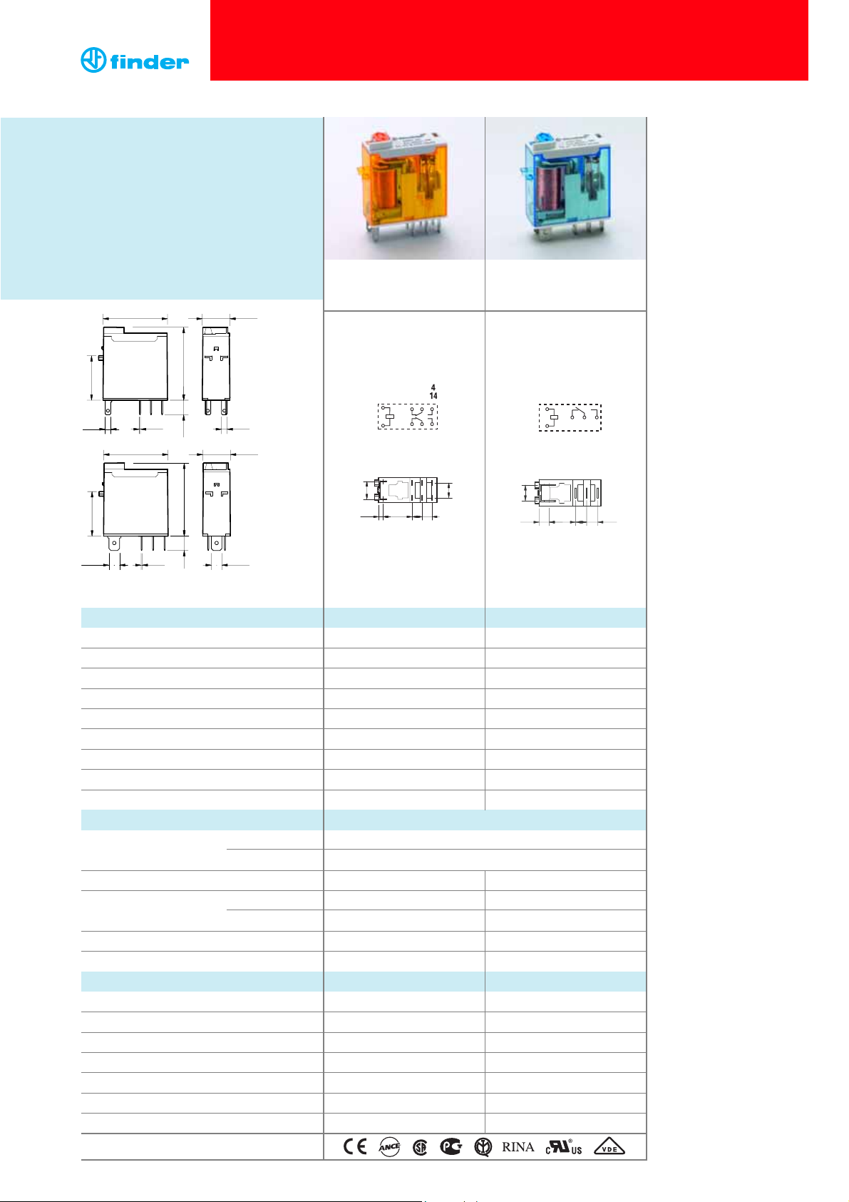
46.52
46 Series - Miniature industrial relays, 8 - 16 A
Contact specification
Contact configuration
Rated current/Maximum peak current A
Rated voltage/Maximum switching voltage V AC
Rated load AC1 VA
Rated load AC15 (230 V AC) VA
Single phase motor rating (230 V AC) kW
Breaking capacity DC1: 30/110/220 V A
Minimum switching load mW (V/mA)
Standard contact material
Coil specification
Nominal voltage (U
N
) V AC (50/60 Hz)
V DC
Rated power VA/W
Operating range AC
DC
Holding voltage AC/DC
Must drop-out voltage AC/DC
Technical data
Mechanical life AC/DC cycles
Electrical life at rated load AC1 cycles
Operate/release time ms
Insulation between coil and contacts (1.2/50 µs)
kV
Dielectric strength between open contacts
V AC
Ambient temperature range °C
Environmental protection
Approvals (according to type)
Features
1 & 2 Pole relay range
46.52 - 2 Pole 8 A
46.61 - 1 Pole 16 A
• Socket mount or direct connection via Faston
connectors
• AC coils & DC coils
• Available with: lockable test button,
mechanical indicator & LED indicator
• 8 mm, 6 kV (1.2/50 µs) isolation, coil-contacts
• Cadmium Free contacts
• 1 Pole CO, 16 A
• Plug-in/Faston 187
1 CO (SPDT)
16/25
250/440
4,000
750
0.55
12/0.5/0.15
300 (5/5)
AgNi
1.2/0.5
(0.8...1.1)U
N
(0.73...1.1)U
N
0.8UN/0.4U
N
0.2UN/0.1U
N
10 · 10
6
100 · 10
3
15/5
6 (8 mm)
1,000
–40 ... +70
RT II
46.61
12 - 24 - 48 - 110 - 120 - 230 - 240
12 - 24 - 48 - 110 - 125
1
46.52
46.61
FORUL H
ORSEPOWER ANDPILOTDUTY RATINGS
SEE“General technical information” page
V
29 12.4
20
2.5 0.5 2.5
29 12.4
20
4.75 0.5 4.75
32.86.5
32.8
6.5
8
3
2
12 11
A1
A2
222421
765
1
8.9
5
5
14.4
2.2
5
2
4
3
12
14
11
5.2
5.2
A1
A2
1
7.4
7.5
4.8 12.3
Page 2
2
Example: 46 series Miniature industrial relay, 1 CO (SPDT), 24 V DC coil, lockable test button and mechanical indicator.
A: Contact material
0 = AgNi
4 = AgSnO
2
(46.61 only)
5 = AgNi + Au (5 µm)
B: Contact circuit
0 = CO (nPDT)
Series
Type
5 = Spade/blade solder terminal
(2.5x0.5)mm
6 = Spade/blade terminal
Faston 187 (4.8x0.5)mm
No. of poles
1 = 1 pole, 16 A
2 = 2 poles, 8 A
Coil version
9 = DC
8 = AC (50/60 Hz)
Coil voltage
See coil specifications
6 1 09
D: Special versions
0 = Standard
C: Options
2 = Mechanical indicator
4 = Lockable test button +
mechanical indicator
54 =Lockable test button + LED (AC) +
mechanical indicator
74 =Lockable test button + double LED
(DC non-polarized) + mechanical indicator
Ordering information
ABCD
... .
02446
46 Series - Miniature industrial relays, 8 - 16 A
0 4 0
Type Coil version A B C D
46.52 AC - DC 0 - 5 0 2 - 40
AC 0 - 5 0 54 /
DC 0 - 5 0 74 /
46.61 AC - DC 0 - 4 - 5 0 2 - 40
AC 0 - 4 - 5 0 54 /
DC 0 - 4 - 5 0 74 /
Selecting features and options: only combinations in the same row are possible.
Preferred selections for best avaliability are shown in bold.
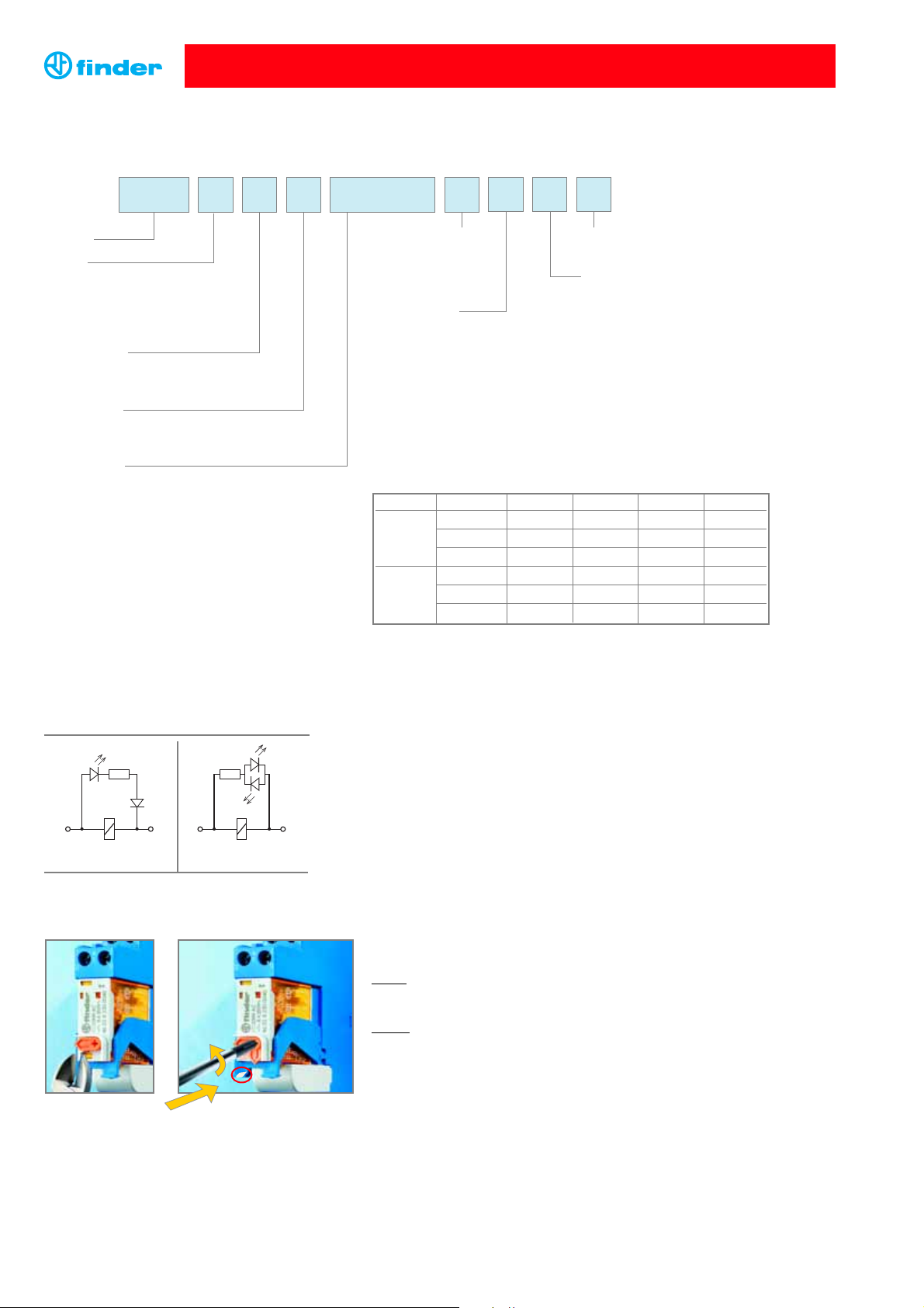
Lockable test button and mechanical flag indicator
(0040, 0054, 0074)
The dual-purpose Finder test button can be used in two ways:
Case 1
) The plastic pip (located directly below the test button) remains intact. In this case, when
the test button is pushed, the contacts operate. When the test button is released the contacts return
to their former state.
Case 2) The plastic pip is broken-off (using an appropriate cutting tool). In this case, (in addition
to the above function), when the test button is pushed and rotated, the contacts are latched in
the operating state, and remain so until the test button is rotated back to its former position.
In both cases ensure that the test button actuation is swift and decisive.
1
8 A2
A2
5 1
A1
8
5
A1
C: Option 54
LED (AC)
C: Option 74
LED (DC, non-polarized)
Descriptions: Options
Page 3

Insulation according to EN 61810-1:2004
1 pole 2 pole
Nominal voltage of supply system V AC 230/400 230/400
Rated insulation voltage V AC 250 400 250 400
Pollution degree 3 2 3 2
Insulation between coil and contact set
Type of insulation Reinforced (8 mm) Reinforced (8 mm)
Overvoltage category III III
Rated impulse voltage kV (1.2/50 µs) 6 6
Dielectric strength V AC 4,000 4,000
Insulation between adjacent contacts
Type of insulation — Basic
Overvoltage category — III
Rated impulse voltage kV (1.2/50 µs) — 4
Dielectric strength V AC — 2,000
Insulation between open contacts
Type of disconnection Micro-disconnection Micro-disconnection
Dielectric strength V AC/kV (1.2/50 µs) 1,000/1.5 1,000/1.5
Conducted disturbance immunity
Burst (5...50)ns, 5 kHz, on A1 - A2 EN 61000-4-4 level 4 (4 kV)
Surge (1.2/50 µs) on A1 - A2 (differential mode) EN 61000-4-5 level 3 (2 kV)
Other data 46.61 46.52
Bounce time: NO/NC ms 2/6 1/4
Vibration resistance (10…150)Hz: NO/NC g 20/12 20/15
Shock resistance g 20 20
Power lost to the environment without contact current W 0.6 0.6
with rated current W 1.6 2
Technical data
3
46 Series - Miniature industrial relays, 8 - 16 A
Cycles
Contact specification
F 46 - Electrical life (AC) v contact current
Type 46.61
• When switching a resistive load (DC1) having voltage and current
values under the curve, an electrical life of ≥ 100·10
3
can be expected.
• In the case of DC13 loads, the connection of a diode in parallel with
the load will permit a similar electrical life as for a DC1 load.
Note: the release time for the load will be increased.
H 46 - Maximum DC1 breaking capacity
DC breaking current (A)
DC voltage (V)
Cycles
F 46 - Electrical life (AC) v contact current
Type 46.52
Resistive load - cosϕ = 1
Inductive load - cosϕ = 0.4
Resistive load - cosϕ = 1
Inductive load - cosϕ = 0.4
46.61 current limit
46.52 current limit
7
10
6
10
5
10
0
20
10
6
4
2
1
4
7
10
6
10
5
10
62
8
(A)
8
1240
16
(A)
0.2
0.1
20 60
100 140 180 220
Page 4

4
046.05
060.72
Accessories
Flange mount adaptor for relays types 46.52 and 46.61 046.05
Sheet of marker tags for relays types 46.52 and 46.61 (72 tags), 6x12mm 060.72
046.07
35 mm rail adaptor for relays types 46.52 and 46.61 046.07
046.05 with relay
046.07 with relay
38
46
14.4
3.6
18.1
36.6
2
046.05 046.05 with relay
046.07 046.07 with relay
Nominal Coil Operating range Resistance Rated coil
voltage code
consumption
U
N
U
min
U
max
R I at U
N
VVVΩ mA
12 9.012 8.8 13.2 300 40
24 9.024 17.5 26.4 1,200 20
48 9.048 35 52.8 4,800 10
110 9.110 80 121 23,500 4.7
125 9.125 91.2 137.5 32,000 3.9
DC coil data
Coil specifications
Nominal Coil Operating range Resistance Rated coil
voltage code
consumption
U
N
U
min
U
max
R I at U
N
VVVΩ mA
12 8.012 9.6 13.2 80 90
24 8.024 19.2 26.4 320 45
48 8.048 38.4 52.8 1,350 21
110 8.110 88 121 6,900 9.4
120 8.120 96 132 9,000 8.4
230 8.230 184 253 28,000 5
240 8.240 192 264 31,500 4.1
AC coil data
1 - Max. permitted coil voltage.
2 - Min. pick-up voltage with coil at ambient temperature.
R 46 - DC coil operating range v ambient temperature
1 - Max. permitted coil voltage.
2 - Min. pick-up voltage with coil at ambient temperature.
R 46 - AC coil operating range v ambient temperature
46 Series - Miniature industrial relays, 8 - 16 A
U
2.0
U
N
1.5
1
1.0
2
0.5
-20
04020 80
60
(°C)
U
2.0
U
N
1.5
1
1.0
2
0.5
-20
04020
60
14.4
46
38
36.6
2
80
(°C)
3.6
18.1
35.1
14.4
46.9
34.8
35.4
42.4
39.8
46.9
14.4
35.4
42.4
38.3
Page 5

5
097.01
97 Series - Sockets and accessories for 46 series relays
Screw terminal socket panel or 35 mm rail (EN 50022) mount
97.01 (blue)
97.01.0 (black)
97.02 (blue)
97.02.0 (black)
For relay type 46.61 46.52
Accessories
Plastic retain and release clip 097.01
(supplied with socket - packaging code SPA)
Identification tag 095.00.4
8-way jumper link 095.18 (blue) 095.18.0 (black)
Modules (see table below) 99.02
Timer modules (see table below) 86.30
Technical data
Rated current
16 A - 250 V AC 8 A - 250 V AC
Dielectric strength 6 kV (1.2/50 µs) between coil and contacts
Protection category IP 20
Ambient temperature °C –40…+70 (see diagram L97)
Screw torque Nm 0.8
Wire strip length mm 8
Max. wire size for 97.01 and 97.02 sockets solid wire stranded wire
mm21x6 / 2x2.5 1x4 / 2x2.5
AWG 1x10 / 2x14 1x12 / 2x14
99.02
99.02 coil indication and EMC suppression modules for 97.01 and 97.02 sockets
Diode (+A1, standard polarity) (6...220)V DC 99.02.3.000.00
LED (6...24)V DC/AC 99.02.0.024.59
LED (28...60)V DC/AC 99.02.0.060.59
LED (110...240)V DC/AC 99.02.0.230.59
LED + Diode (+A1, standard polarity) (6...24)V DC 99.02.9.024.99
LED + Diode (+A1, standard polarity) (28...60)V DC 99.02.9.060.99
LED + Diode (+A1, standard polarity) (110...220)V DC 99.02.9.220.99
LED + Varistor (6...24)V DC/AC 99.02.0.024.98
LED + Varistor (28...60)V DC/AC 99.02.0.060.98
LED + Varistor (110...240)V DC/AC 99.02.0.230.98
RC circuit (6...24)V DC/AC 99.02.0.024.09
RC circuit (28...60)V DC/AC 99.02.0.060.09
RC circuit (110...240)V DC/AC 99.02.0.230.09
Residual current by-pass (110...240)V AC 99.02.8.230.07
095.18
15 1515.815.815.815.815.8
7 3.3
110.5
10.3
5.1
86.30
86 series timer module
(12…24)V AC/DC; Bi-function: AI, DI; (0.05s…100h)
86.30.0.024.0000
(230...240)V AC; Bi-function: AI, DI; (0.05s…100h)
86.30.8.240.0000
DC Modules with
non-standard polarity
(+A2) on request.
Approvals
(according to type):
Approvals
(according to type):
8-way jumper link for 97.01 and 97.02 sockets 095.18 (blue) 095.18.0 (black)
Rated values 10 A - 250 V
97.01
Approvals
(according to type):
Rated current (A)
(°C)
60
20
-20
10
0
04020 80
12
16
8
6
4
2
14
18
L 97 - Rated current vs ambient temperature
(for 46.61 relay / 97.01 socket combination)
97.01
97.02
97.02
1
5
.8
8
2
.8
5
3
2
Ø 3.2
97.01
4
11
1A2 5
6
8
.4
6
4
.9
2
1
6
9
1
5
6
COM
3
NO
14
2
NC
12
COIL
A1
21
5244
7222
1A2 8
3
COM
11
NO
14
NC
12
COIL
A1
.8
5
.8
Ø 3.2
2
8
2
3
.5
5
.8
5
2
.4
5
3
.6
1
2
3
5
.3
1
.2
9
.2
Page 6

97.51
97 Series - Sockets and accessories for 46 series relays
Screwless terminal socket panel or 35 mm rail (EN 50022) mount
97.51 (blue)
97.51.0 (black)
97.52 (blue)
97.52.0 (black)
For relay type 46.61 46.52
Accessories
Plastic retain and release clip 097.01
(supplied with socket - packaging code SPA)
Modules (see table below) 99.02
Timer modules (see table below) 86.30
Technical data
Rated current
10 A - 250 V AC 8 A - 250 V AC
Dielectric strength 6 kV (1.2/50 µs) between coil and contacts
Protection category IP 20
Ambient temperature °C –25…+70
Wire strip length mm 8
Max. wire size for 97.51 and 97.52 sockets solid wire stranded wire
mm22x(0.2...1.5) 2x(0.2...1.5)
AWG 2x(24...18) 2x(24...18)
99.02
99.02 coil indication and EMC suppression modules for 97.51 and 97.52 sockets
Diode (+A1, standard polarity) (6...220)V DC 99.02.3.000.00
LED (6...24)V DC/AC 99.02.0.024.59
LED (28...60)V DC/AC 99.02.0.060.59
LED (110...240)V DC/AC 99.02.0.230.59
LED + Diode (+A1, standard polarity) (6...24)V DC 99.02.9.024.99
LED + Diode (+A1, standard polarity) (28...60)V DC 99.02.9.060.99
LED + Diode (+A1, standard polarity) (110...220)V DC 99.02.9.220.99
LED + Varistor (6...24)V DC/AC 99.02.0.024.98
LED + Varistor (28...60)V DC/AC 99.02.0.060.98
LED + Varistor (110...240)V DC/AC 99.02.0.230.98
RC circuit (6...24)V DC/AC 99.02.0.024.09
RC circuit (28...60)V DC/AC 99.02.0.060.09
RC circuit (110...240)V DC/AC 99.02.0.230.09
Residual current by-pass (110...240)V AC 99.02.8.230.07
86.30
86 series timer module
(12…24)V AC/DC; Bi-function: AI, DI; (0.05s…100h)
86.30.0.024.0000
(230...240)V AC; Bi-function: AI, DI; (0.05s…100h)
86.30.8.240.0000
DC Modules with
non-standard polarity
(+A2) on request.
Approvals
(according to type):
Approvals (according to type):
How to code and identify retaining clip and packaging options for sockets. Example:
0 1
.
97
Packaging codes
A Standard packaging
Without retaining clip
SP Plastic retaining clip
SP A
0 1
.
97
97.51
Approvals
(according to type):
097.01
2,5 mm
COIL
A2
1
5
A1
12
NC
14
11
COM
NO
3
2
4
1
5
.
8
9
5
.
6
2
2
.
6
3
2
.5
3
0
.3
3
4
.7
3
0
.6
2
4
.6
6
2
.7
3
4
4
38.3
Ø 3.2
COIL
4
11
COM
NO
NC
3
14
2
12
1A2 5
A1
97.51
97.51
97.52
97.52
6
2
4
.6
6
3
COM
21
5244
7222
11
NO
14
NC
12
95.6
11
21
COM
6
3
14NO24
5
4
7
2
NC 12
22
Ø 3.2
6
2
.7
3
4
4
1A2 8
COIL
A1
37.2
A2
1
COIL
1
5
8
A1
.
8
30.3 34.7 30.6
2
2
.6
3
2
.5
 Loading...