

Page 1
38
115
Features
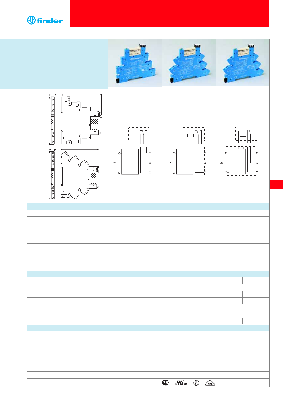
1 Pole - 6 A electromechanical relay
interface modules, 6.2 mm wide.
Ideal interface for PLC and electronic systems
• Sensitive DC coil or AC/DC coil versions
• Integral coil indication and protection circuit
• Instant ejection of relay using plastic
retaining clip
• UL Listed
• 35 mm rail (EN 50022) mounting
1 CO (SPDT) 1 CO (SPDT) 1 CO (SPDT)
6/10 6/10 6/10
250/400 250/400 250/400
1,500 1,500 1,500
300 300 300
0.185 0.185 0.185
6/0.2/0.15 6/0.2/0.15 6/0.2/0.15
500 (12/10) 500 (12/10) 500 (12/10)
AgNi AgNi AgNi
12 - 24 - 48 - 60 - (110…125) - (220…240) (
110…125)
(230…240)AC only
6 - 12 - 24 - 48 - 60 (non polarized) —
see page 121 see page 121 1/1 0.5/—
(0.8...1.1)U
N
(0.8...1.1)U
N
(94...138)UN(184...264)U
N
(0.8...1.2)U
N
(0.8...1.2)U
N
—
0.6 U
N
/ 0.6 U
N
0.6 UN / 0.6 U
N
0.6 UN / 0.6 U
N
0.1 UN / 0.05 U
N
0.1 UN / 0.05 U
N
44 V 92 V
10 · 10
6
10 · 10
6
10 · 10
6
60 · 10
3
60 · 10
3
60 · 10
3
5/6 5/6 5/6
6 (8 mm) 6 (8 mm) 6 (8 mm)
1,000 1,000 1,000
–40…+70/–40...+55 –40…+70/–40...+55 —/–40...+55
IP 20 IP 20 IP 20
38.51 38.61 38.51.3 / 38.61.3
38 Series - Relay interface modules 0.1 - 2 - 6 - 8 A
• Screw terminal
•
1 pole electromechanical relay
• 35 mm rail mounting
• Screwless terminal
•
1 pole electromechanical relay
• 35 mm rail mounting
• Leakage current suppression
•
1 pole electromechanical relay
• 35 mm rail mounting
Contact specification
Contact configuration
Rated current/Maximum peak current A
Rated voltage/Maximum switching voltage V AC
Rated load AC1 VA
Rated load AC15 (230 V AC) VA
Single phase motor rating (230 V AC) kW
Breaking capacity DC1: 30/110/220 V A
Minimum switching load mW (V/mA)
Standard contact material
Coil specification
Nominal voltage (U
N
) V AC/DC
V DC
Rated power AC/DC VA (50 Hz)/W
Operating range AC/DC
DC
Holding voltage AC/DC
Must drop-out voltage AC/DC
Technical data
Mechanical life cycles
Electrical life at rated load AC1 cycles
Operate/release time ms
Insulation between coil and contacts (1.2/50 µs) kV
Dielectric strength between open contacts V AC
Ambient temperature range (≤ 60 V/>60 V) °C
Protection category
Approvals relay (according to type)
38.51
38.61
12
11
14
220-240
V~
A1
A2
75.6
93
6.2
75.6
87.3
6.2
A1
A2
protection
and
indication
circuit
14
11
12
A1
protection
and
indication
circuit
A2
A1
14
11
leakage
current
suppression
circuit
A2
12
14
11
12
Page 2
116
38
Features
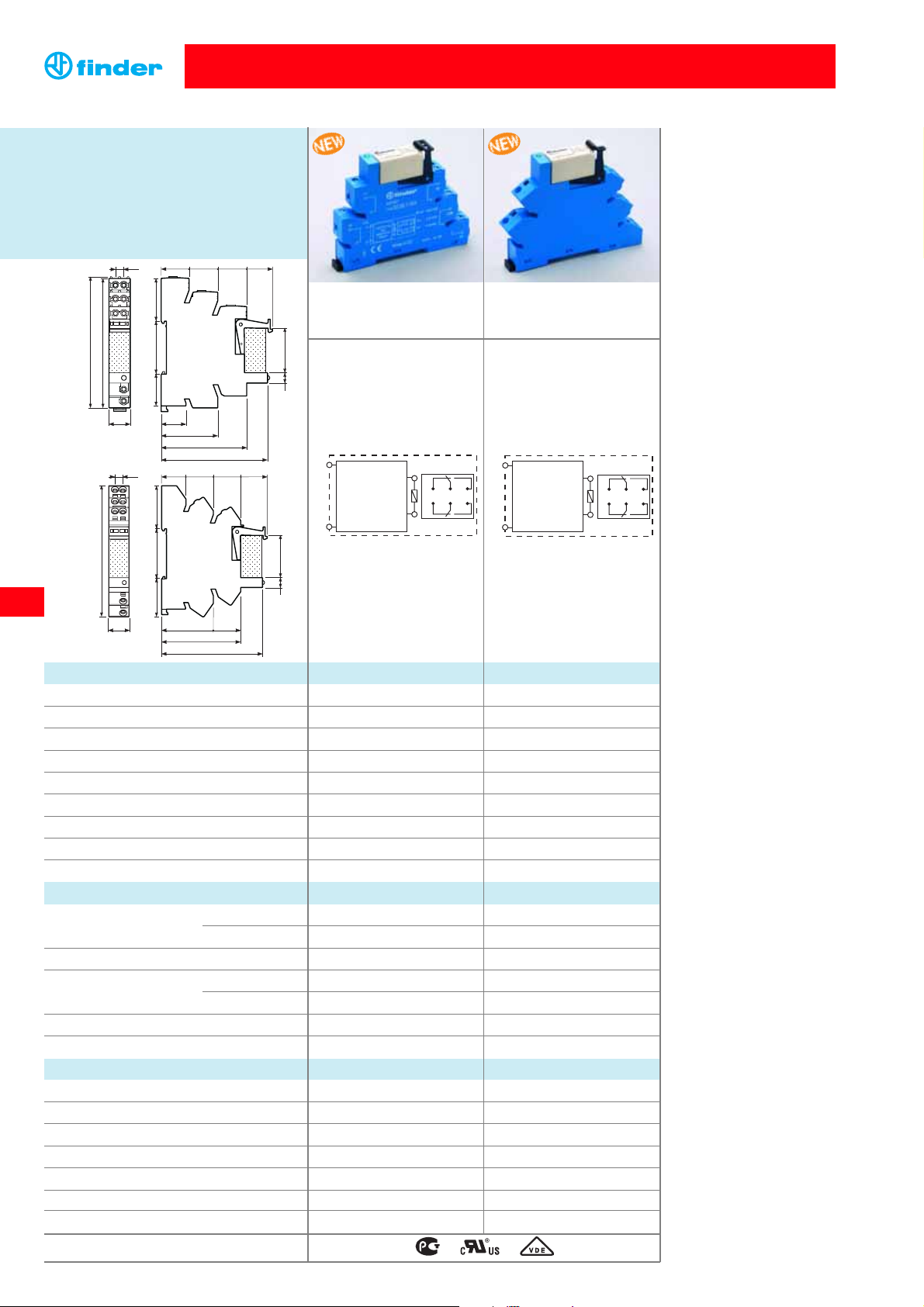
2 Pole - 8 A electromechanical relay
interface modules, 14 mm wide.
Ideal interface for PLC and electronic systems
• Sensitive DC coil versions
• Integral coil indication and protection circuit
•
Instant ejection of relay using plastic retaining clip
• 35 mm rail (EN 50022) mounting
2 CO (DPDT) 2 CO (DPDT)
8/15 8/15
250/400 250/400
2,000 2,000
400 400
0.3 0.3
8/0.3/0.12 8/0.3/0.12
300 (5/5) 300 (5/5)
AgNi AgNi
——
12 - 24 - 60 12 - 24 - 60
—/0.5 —/0.5
——
(0.8...1.2)U
N
(0.8...1.2)U
N
— / 0.6 U
N
— / 0.6 U
N
— / 0.05 U
N
— / 0.05 U
N
30 · 10
6
30 · 10
6
80 · 10
3
80 · 10
3
——
6 (8 mm) 6 (8 mm)
1,000 1,000
–40…+70 –40…+70
IP 20 IP 20
38.52 38.62
38 Series - Relay interface modules 0.1 - 2 - 6 - 8 A
• Screw terminal
•
2 pole electromechanical relay
• 35 mm rail mounting
• Screwless terminal
•
2 pole electromechanical relay
• 35 mm rail mounting
Contact specification
Contact configuration
Rated current/Maximum peak current A
Rated voltage/Maximum switching voltage V AC
Rated load AC1 VA
Rated load AC15 (230 V AC) VA
Single phase motor rating (230 V AC) kW
Breaking capacity DC1: 30/110/220 V A
Minimum switching load mW (V/mA)
Standard contact material
Coil specification
Nominal voltage (U
N
) V AC/DC
V DC
Rated power AC/DC VA (50 Hz)/W
Operating range AC/DC
DC
Holding voltage AC/DC
Must drop-out voltage AC/DC
Technical data
Mechanical life cycles
Electrical life at rated load AC1 cycles
Operate/release time ms
Insulation between coil and contacts (1.2/50 µs) kV
Dielectric strength between open contacts V AC
Ambient temperature range °C
Protection category
Approvals relay (according to type)
38.52
38.62
71.6
16.7
38.1
57.6
22.8 35.6 28.8
18.8
19.3 19.5 17.3
7 30
87.2
5.6
14.3
88.4
36.7
56.1
71.6
27.05 35.4 30.55
17.3 19.4 19.4 18.8
7 30
5.6
14.3
88.4
19.4
PROTECTION
AND
INDICATION
CIRCUIT
A1
A2
22 12
21 11
24 14
PROTECTION
AND
INDICATION
CIRCUIT
A1
A2
22 12
21 11
24 14
Page 3
38
117
Features
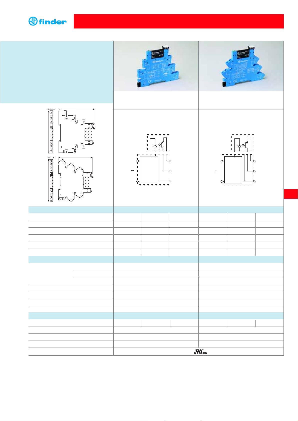
Single output - solid state relay interface
modules, 6.2 mm wide
Ideal interface for PLC and electronic systems
• DC, AC or AC/DC input versions
• Supplied with integral coil indication and
protection circuit
• Silent, high switching speed and
long electrical life
•
Instant ejection of relay using plastic retaining clip
• UL listed
•35 mm rail (EN 50022) mounting
2/20 0.1/0.5 2/40 2/20 0.1/0.5 2/40
24/33 DC 48/60 DC 240/275 AC 24/33 DC 48/60 DC 240/275 AC
(1.5…24)DC (1.5…48)DC (12...240)AC (1.5…24)DC (1.5…48)DC (12…240)AC
1 0.05 22 1 0.05 22
0.001 0.001 1.5 0.001 0.001 1.5
0.12 1 1.6 0.12 1 1.6
0...24 0...48
— 230...240
6 - 24 - 60 —
(110...125) - (220...240) 110...125
See table page 122 See table page 122
See table page 122 See table page 122
See table page 122 See table page 122
See table page 122 See table page 122
0.1/0.4 0.02/0.11 12/12 0.1/0.4 0.02/0.11 12/12
2,500 2,500
–20...+55 –20...+55
IP20 IP20
38.81/38.91 38.81.3/38.91.3
• AC or DC output switching
• SSR relay - DC input voltage
• 35 mm rail mounting
•
AC or DC output - Leakage current suppression
• SSR relay - AC or AC/DC input voltage
• 35 mm rail mounting
Output circuit
Rated current/Maximum peak current (10 ms) A
Rated voltage/Maximum blocking voltage V
Switching voltage range V
Minimum switching current mA
Max. “OFF-state” leakage current mA
Max. “ON-state” voltage drop V
Input circuit
V AC
Nominal voltage (U
N
)V DC
V AC/DC
Operating range V DC
Control current mA
Release voltage V DC
Impedance Ω
Technical data
Operate/release time µs
Dielectric strength between input/output V
Ambient temperature range °C
Environmental protection
Approvals (according to type)
protection
and
indication
circuit
14
11 (13+)
A1
A2
protection
and
indication
circuit
14
11 (13+)
A1
A2
38.81
38.91
38 Series - Relay interface modules 0.1 - 2 - 6 - 8 A
12
11
14
220-240
V~
A1
A2
75.6
93
6.2
75.6
87.3
6.2
Page 4

118
38
Example: 38 series relay interface module, 1 CO (SPDT), 12 V DC coil.
Series
Type
5 = Electromechanical relay,
with screw terminal
6 = Electromechanical relay,
with screwless terminal
No. of poles
1 = 1 pole, 6 A
Coil version
0 = AC (50/60 Hz)/ DC
3 = Leakage current suppression
for (110…125)V AC/DC - (230…240)V AC only
7 = Sensitive DC
Coil voltage
see coil specifications
5 1 0 07
D: Special versions
0 = Standard
C: Options
5 = Standard DC
6 = Standard AC/DC
B: Contact circuit
0 = CO (nPDT)
A: Contact material
0 = AgNi Standard
4 = AgSnO
2
5 = AgNi + Au
5 0
Ordering information
ABCD
... .
01238
Electromechanical relay 1 Pole
38 Series - Relay interface modules 0.1 - 2 - 6 - 8 A
Example: 38 series relay interface module, 2 CO (DPDT), 12 V DC coil.
Series
Type
5 = Electromechanical relay,
with screw terminal
6 = Electromechanical relay,
with screwless terminal
No. of poles
2 = 2 pole, 8 A
Coil version
7 = Sensitive DC
Coil voltage
see coil specifications
5 2 0 07
D: Special versions
0 = Standard
C: Options
5 = Standard DC
B: Contact circuit
0 = CO (nPDT)
A: Contact material
0 = AgNi Standard
5 0
ABCD
... .
01238
Electromechanical relay 2 Pole
Electromechanical Relay
Page 5

119
38
Example: 38 series SSR relay interface module, 2 A, 24 V DC supply.
Output circuit
9024 = 2 A - 24 V DC
7048 = 0.1 A - 48 V DC
8240 = 2 A - 240 V AC
Series
Type
8 = SSR relay, with screw terminal
9 =
SSR relay, with screwless terminal
Output
1 = 1 NO (SPST-NO)
Supply version
0 = AC/DC for (110...125)V and (230...240)V only
3 = Leakage current suppression
for (110...125)V AC/DC and (230...240)V AC only
7 = DC
Supply voltage
see input specifications
8 1
.. .
38
9 0 2 4
7
.
024
Solid state relay
38 Series - Relay interface modules 0.1 - 2 - 6 - 8 A
Ordering information
Solid State Relay
Page 6

38
120
Insulation
Insulation according to EN 61810-1 ed. 2 insulation rated voltage V 250 400
rated impulse withstand voltage kV 4 4
pollution degree 3 2
overvoltage category III III
Insulation between coil and contacts (1.2/50 µs)
kV
6 (8 mm)
Dielectric strength between open contacts V AC 1,000
Conducted disturbance immunity
Burst (5...50)ns, 5 kHz, on A1 - A2 EN 61000-4-4 level 4 (4 kV)
Surge (1.2/50 µs) on A1 - A2 (differential mode) EN 61000-4-5 level 3 (2 kV)
Other data 1 Pole 2 Pole
Bounce time: NO/NC ms 1/6 2/5
Vibration resistance (10…55)Hz, max. ± 1 mm: NO/NC g/g 10/5 15/2
Power lost to the environment without contact current W 0.2 (12 V) - 0.9 (240 V) 0.5
with rated current W 0.5 (12 V) - 1.5 (240 V) 1.3
38.51/52 38.61/62
Wire strip length mm 10 10
Screw torque Nm 0.5 —
Max. wire size solid cable
stranded cable
solid cable
stranded cable
mm2 1x2.5/2x1.5 1x2.5/2x1.5
1x2.5 1x2.5
AWG 1x14/2x16 1x14/2x16 1x14 1x14
38 Series - Relay interface modules 0.1 - 2 - 6 - 8 A
Technical data
Electromechanical Relay
10
6
10
5
10
7
10
4
62
0
8
4
(A)
Contact specification
F 38 - Electrical life (AC) v contact current, 1 Pole
Cycles
20 60
100 140 180 220
20
10
6
4
2
1
0.2
0.1
DC voltage (V)
DC breaking current (A)
H 38 - Maximum DC1 breaking capacity, 1 Pole
Resistive load - cosϕ = 1
Inductive load - cosϕ = 0.4
10
6
10
5
10
7
10
4
1240
16
8
(A)
F 38 - Electrical life (AC) v contact current, 2 Pole
Cycles
• When switching a resistive load (DC1) having voltage and current
values under the curve, an electrical life of ≥ 60·103(1 Pole) or
≥ 80·103 ( 2 Pole) can be expected.
• In the case of DC13 loads, the connection of a diode in parallel with
the load will permit a similar electrical life as for a DC1 load.
Note: the release time for the load will be increased.
20 60
100 140 180 220
20
10
6
4
2
1
0.2
0.1
DC voltage (V)
DC breaking current (A)
H 38 - Maximum DC1 breaking capacity, 2 Pole
Resistive load - cosϕ = 1
Inductive load - cosϕ = 0.4
2 contacts in series
single contact
Page 7

121
38
Nominal Coil Operating range Rated coil Power
voltage code
consumption consumption
U
N
U
min
U
max
I at U
N
P at U
N
VVVmAW
12 0.012 9.8 13.2 16 0.2
24 0.024 19.2 26.4 12 0.2
48 0.048 38.4 52.8 6.9 0.3
60 0.060 48 66 7 0.5
110…125
0.125 88 138 5(*) 0.6(*)
220…240
0.240 184 264 4(*) 0.9(*)
Coil data AC/DC, 1 Pole
Coil specifications
Nominal Coil Operating range Rated coil Power
voltage code
consumption consumption
U
N
U
min
U
max
I at U
N
P at U
N
VVVmAW
6 7.006 5 7.2 35 0.2
12 7.012 9.8 14.4 15.2 0.2
24 7.024 18.2 28.8 10.4 0.3
48 7.048 35 57.6 6.3 0.3
60 7.060 43.5 72 7 0.4
Coil data sensitive DC, 1 Pole
1 - Max. permitted coil voltage at nominal load (DC coil).
2 - Max. permitted coil voltage at nominal load (AC/DC coils < 60 V).
3 - Max. permitted coil voltage at nominal load (AC/DC coils > 60 V).
4 - Min pick-up voltage with coil at ambient temperature.
(*) Rated coil consumption and power consumption values relate to
U
N
= 125 and 240 V.
(*) Rated coil consumption and power consumption values relate to U
N
= 125 and 240 V.
Nominal Coil Operating range Must Rated coil Power
voltage code drop out
consumption consumption
U
N
U
min
U
max
U I at U
N
P at U
N
VVVmAW
(110…125) AC/DC 3.125 94 138 44 8(*) 1(*)
(230…240) AC 3.240 184 264 92 7(*) 0.5(*)
Coil data, leakage current suppression types, 1 Pole
38 Series - Relay interface modules 0.1 - 2 - 6 - 8 A
Electromechanical Relay 1 Pole
60
2.0
-20
1.0
0.5
1.5
04020
U
U
N
80
1
3
(°C)
2
4
R 38 - DC coil operating range v ambient temperature
1 Pole and 2 Pole
Electromechanical Relay 2 Pole
Coil specifications
Nominal Coil Operating range Rated coil
voltage code consumption
U
N
U
min
U
max
I at U
N
VVVmA
12 7.012 9.6 14.4 41
24 7.024 19.2 28.8 19.5
60 7.060 48 72 8
Coil data sensitive DC, 2 Pole
The 38 Series interface modules (supply version
3) have built-in leakage current suppression to
address industry concerns of the contacts not
dropping-out when there is residual current in the
circuit; at (110...125)V AC and (230...240)V AC.
This problem can occur, for example, when
connecting the interface modules to PLC‚s with
triac outputs or when connecting via relatively
long cables.
Page 8

122
38
38 Series - Relay interface modules 0.1 - 2 - 6 - 8 A
Nominal Supply Operating range Release Control
voltage code voltage current
U
N
U
min
U
max
U I at U
N
VVVVmA
6 7.006 5 7.2 2.4 7
24 7.024 16.8 30 10 10.5
60 7.060 35.6 72 20 6.5
Input specification
Nominal Supply Operating range Release
Rated coil
Power
voltage code voltage
consumption consumption
U
N
U
min
U
max
U I at UNP at U
N
VVVmAW
110…125 AC/DC
3.125 94 138 44 8(*) 1(*)
230…240 AC
3.240 184 264 72 5.6(*) 0.5(*)
(*) Rated coil consumption and power consumption values relate to
UN= 125 and 240 V.
Solid State Relay
Other data
Power lost to the environment without output current W 0.17
with rated current W 0.4
38.81 38.91
Wire strip length mm 10 10
Screw torque Nm 0.5 —
Max. wire size solid cable stranded cable solid cable stranded cable
mm2 1x2.5 / 2x1.5 1x2.5 / 2x1.5 1x2.5 1x2.5
AWG 1x14 / 2x16 1x14 / 2x16 1x14 1x14
Technical data
Input data - DC
Input data - Leakage current suppression types
Nominal Supply Operating range Release Control
voltage code voltage current
U
N
U
min
U
max
U I at U
N
VVVVmA
110...125 0.125 88 138 45 5
230...240 0.240 184 264 90 4.5
Input data - AC/DC
The 38 Series interface modules (supply version 3) have built-in leakage
current suppression to address industry concerns of the contacts not
dropping-out when there is residual current in the circuit; at (110...125)V
AC and (230...240)V AC.
This problem can occur, for example, when connecting the interface
modules to PLC‚s with triac outputs or when connecting via relatively long
cables.
Page 9

38
123
93.51
93.01
Screw terminal - 1 Pole relay
Code Supply voltage Type of relay Type of socket
38.51.0.012.0060 12 V AC/DC 34.51.7.012.0010 93.01.0.024
38.51.0.024.0060 24 V AC/DC 34.51.7.024.0010 93.01.0.024
38.51.0.048.0060 48 V AC/DC 34.51.7.048.0010 93.01.0.060
38.51.0.060.0060 60.V AC/DC 34.51.7.060.0010 93.01.0.060
38.51.0.125.0060 (110...125)V AC/DC 34.51.7.060.0010 93.01.0.125
38.51.0.240.0060 (220...240)V AC/DC 34.51.7.060.0010 93.01.0.240
38.51.3.125.0060 (110...125)V AC/DC 34.51.7.060.0010 93.01.3.125
38.51.3.240.0060 (230...240)V AC 34.51.7.060.0010 93.01.3.240
38.51.7.006.0050 6 V DC 34.51.7.005.0010 93.01.7.024
38.51.7.012.0050 12 V DC 34.51.7.012.0010 93.01.7.024
38.51.7.024.0050 24 V DC 34.51.7.024.0010 93.01.7.024
38.51.7.048.0050 48 V DC 34.51.7.048.0010 93.01.7.060
38.51.7.060.0050 60 V DC 34.51.7.060.0010 93.01.7.060
Screwless terminal - 1 Pole relay
Code Supply voltage Type of relay Type of socket
38.61.0.012.0060 12 V AC/DC 34.51.7.012.0010 93.51.0.024
38.61.0.024.0060 24 V AC/DC 34.51.7.024.0010 93.51.0.024
38.61.0.125.0060 (110...125)V AC/DC 34.51.7.060.0010 93.51.0.125
38.61.0.240.0060 (220...240)V AC/DC 34.51.7.060.0010 93.51.0.240
38.61.3.125.0060 (110...125)V AC/DC 34.51.7.060.0010 93.51.3.125
38.61.3.240.0060 (230...240)V AC 34.51.7.060.0010 93.51.3.240
38.61.7.012.0050 12 V DC 34.51.7.012.0010 93.51.7.024
38.61.7.024.0050 24 V DC 34.51.7.024.0010 93.51.7.024
Screw terminal - 2 Pole relay
Code Supply voltage Type of relay Type of socket
38.52.7.012.0050 12 V DC 41.52.9.012.0010 93.02.7.024
38.52.7.024.0050 24 V DC 41.52.9.024.0010 93.02.7.024
38.52.7.060.0050 60 V DC 41.52.9.060.0010 93.02.7.060
Screwless terminal - 2 Pole relay
Code Supply voltage Type of relay Type of socket
38.62.7.012.0050 12 V DC 41.52.9.012.0010 93.52.7.024
38.62.7.024.0050 24 V DC 41.52.9.024.0010 93.52.7.024
38.62.7.060.0050 60 V DC 41.52.9.060.0010 93.52.7.060
Approvals
(according to type):
Combination for Electromechanical Relay
3 mm
38 Series - Relay interface modules 0.1 - 2 - 6 - 8 A
93.52
93.02
Screw terminal
Code Supply voltage Type of relay Type of socket
38.81.7.006.xxxx 6 V DC 34.81.7.005.xxxx 93.01.7.024
38.81.7.024.xxxx 24 V DC 34.81.7.024.xxxx 93.01.7.024
38.81.7.060.xxxx 60 V DC 34.81.7.060.xxxx 93.01.7.060
38.81.0.125.xxxx (110...125)V AC/DC 34.81.7.060.xxxx 93.01.0.125
38.81.0.240.xxxx (220...240)V AC/DC 34.81.7.060.xxxx 93.01.0.240
38.81.3.125.xxxx (110...125)V AC/DC 34.81.7.060.xxxx 93.01.3.125
38.81.3.240.xxxx (230...240)V AC 34.81.7.060.xxxx 93.01.3.240
Screwless terminal
Code Supply voltage Type of relay Type of socket
38.91.7.006.xxxx 6 V DC 34.81.7.005.xxxx 93.51.7.024
38.91.7.024.xxxx 24 V DC 34.81.7.024.xxxx 93.51.7.024
38.91.7.060.xxxx 60 V DC 34.81.7.060.xxxx 93.51.7.060
38.91.0.125.xxxx (110...125)V AC/DC 34.81.7.060.xxxx 93.51.0.125
38.91.0.240.xxxx (220...240)V AC/DC 34.81.7.060.xxxx 93.51.0.240
38.91.3.125.xxxx (110...125)V AC/DC 34.81.7.060.xxxx 93.51.3.125
38.91.3.240.xxxx (230...240)V AC 34.81.7.060.xxxx 93.51.3.240
Combination for Solid State Relay
Example: .xxxx
.9024
.7048
.8240
Listed: certain relay/
socket combinations
Page 10

38
124
38 Series - Relay interface modules 0.1 - 2 - 6 - 8 A
093.20
20-way jumper link for 1 Pole 093.20
Rated values 36 A - 250 V
093.01
093.64
Thickness 2 mm, required at the start and the end of a group of interfaces.
Can be used for visual separation group, must be used for:
- protective separation of different voltages of neighbouring PLC interfaces according to VDE 0106-101
- protection of cut jumper links
Approvals
(according to type):
Plastic separator 093.01
Sheet of marker tags for 38.x1, plastic, 64 tags, 6x10 mm 093.64
Accessories
093.08
8-way jumper link for 2 Pole 093.08
Rated values 10 A - 250 V
060.72
Sheet of marker tags for 38.x2, plastic, 72 tags, 6x12 mm 060.72
121.5
2.8
10
6.5
6.2 6.26.26.26.26.26.26.26.26.2 1.851.85
12.7 14
7.26.810.5 6.8 6.87.2 6.8 6.87.27.2 6.87.2 10.5
12.714 14 14 14
110°
16.5
0.8
1
6.2 9
9.3
2.85
 Loading...