

Page 1
1 CO (SPDT) 1 NO (SPST-NO)
6/15 6/15
250/400 250/400
1,500 1,500
250 250
0.185 0.185
3/0.35/0.2 3/0.35/0.2
500 (10/5) 500 (10/5)
AgCdO AgCdO
——
5 - 12 - 24 - 48 5 - 12 - 24 - 48
—/0.2 —/0.2
——
(0.78...1.5)U
N
(0.78...1.5)U
N
—/0.4 U
N
—/0.4 U
N
—/0.1 U
N
—/0.1 U
N
—/20 · 10
6
—/20 · 10
6
100 · 10
3
100 · 10
3
6/4 6/2
55
1,000 1,000
–40…+85 –40…+85
RT III RT III
32.21-x000 32.21-x300
1
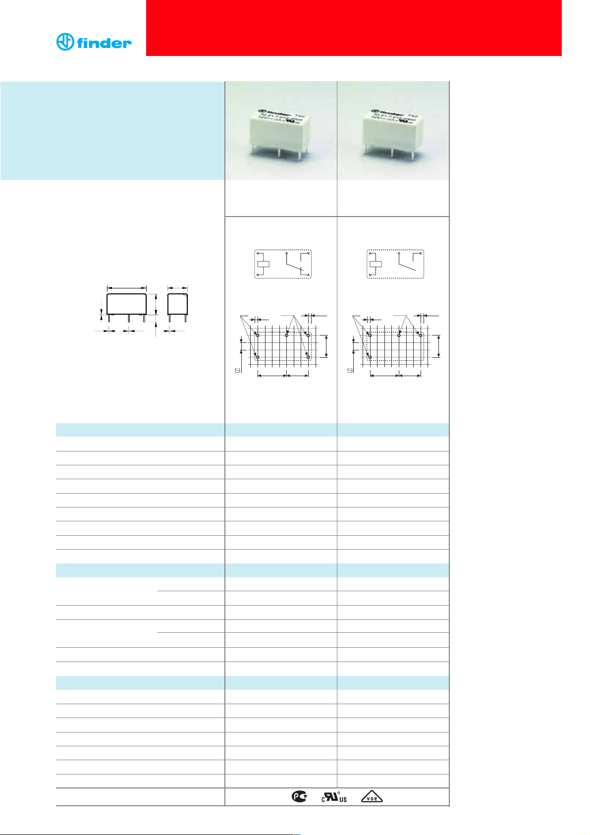
32 Series - Subminiature PCB relays 6 A
Contact specification
Contact configuration
Rated current/Maximum peak current A
Rated voltage/Maximum switching voltage V AC
Rated load AC1 VA
Rated load AC15 (230 V AC) VA
Single phase motor rating (230 V AC) kW
Breaking capacity DC1: 30/110/220 V A
Minimum switching load mW (V/mA)
Standard contact material
Coil specification
Nominal voltage (U
N
) V AC (50/60 Hz)
V DC
Rated power AC/DC VA (50 Hz)/W
Operating range AC
DC
Holding voltage AC/DC
Must drop-out voltage AC/DC
Technical data
Mechanical life AC/DC cycles
Electrical life at rated load AC1 cycles
Operate/release time ms
Insulation between coil and contacts (1.2/50 µs)
kV
Dielectric strength between open contacts V AC
Ambient temperature range °C
Environmental protection
Approvals (according to type)
Copper side view Copper side view
Features
Printed circuit mount 6 A relay
• 1 Pole changeover contacts or
1 Pole normally open contact
• Subminiature, low profile package
• Sensitive DC coil - 200 mW
• Wash tight: RT III
• Cadmium Free contact material option
• 1 CO (SPDT), 6 A
• Low coil power
• PCB mount
• 1 NO (SPST-NO), 6 A
• Low coil power
• PCB mount
20 10
0.4
0.4 0.6 0.4
10.73.5
A1
A2
Ø1
2.54
1.4
Ø1.2 1.1
14
12
7.6210.16
Ø1
7.62
2.54
11
Ø1.2
1411
1.1
7.62
7.6210.16
A1
A2
1.4
Page 2
Technical data
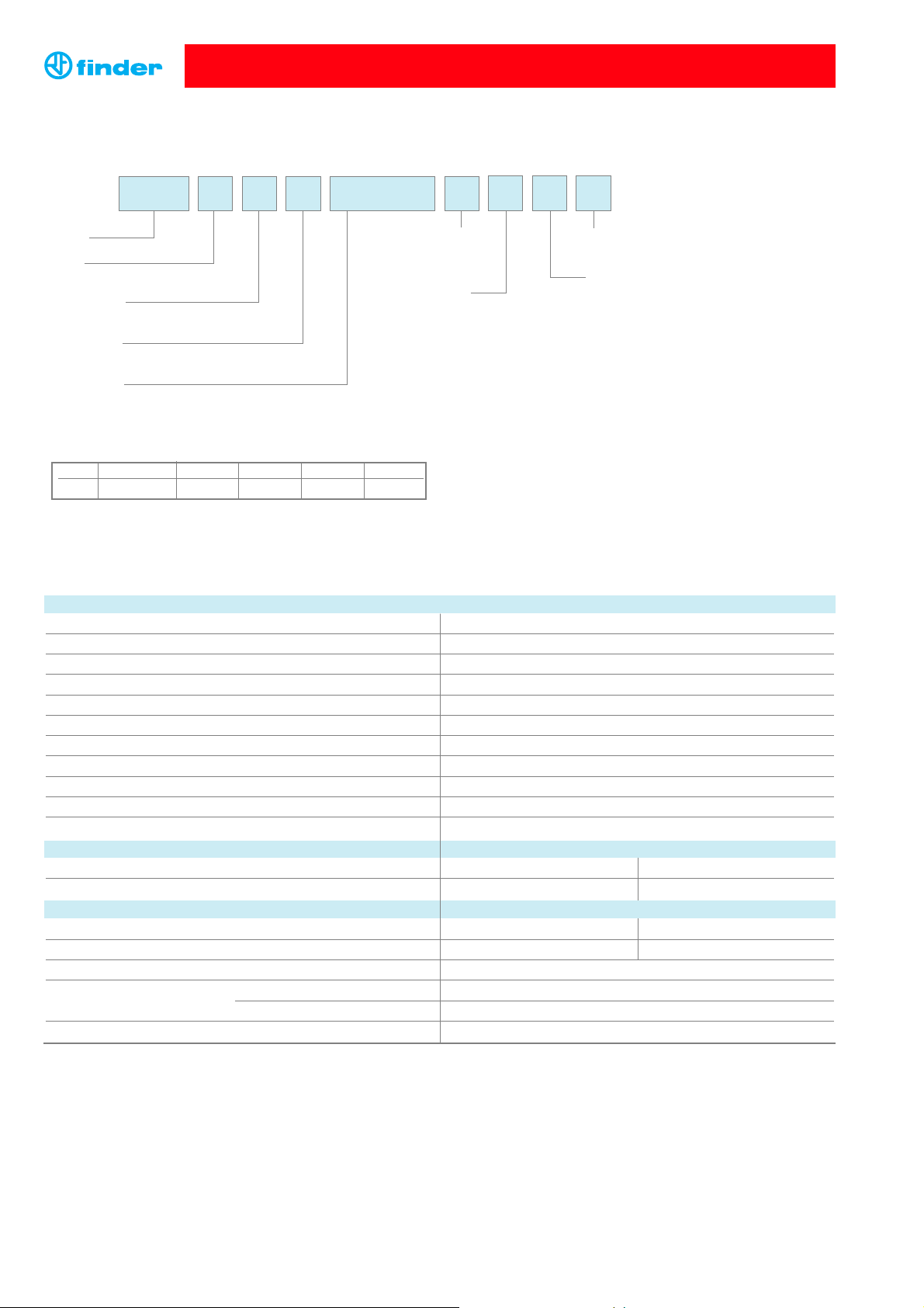
Example: 32 series PCB, 1 NO (SPDT-NO) - 6 A contacts, 24 V sensitive DC coil.
A: Contact material
2 = Standard AgCdO
4 = AgSnO
2
B: Contact circuit
0 = CO (SPDT)
3 = NO (SPST)
Series
Type
2 = PCB mount
No. of poles
1 = 1 pole, 6 A
Coil version
7 = Sensitive DC
Coil voltage
See coil specifications
2 1 27
D: Special versions
0 = Wash tight (RT III)
C: Options
0 = None
Ordering information
ABCD
... .
02432
32 Series - Subminiature PCB relays 6 A
2
3 0 0
Type Coil version A B C D
32.21 sens. DC 2 - 4 0 - 3 0 0
Selecting features and options: only combinations in the same row are possible.
Preferred selections for best avaliability are shown in bold.
Insulation according to EN 61810-1:2004
Nominal voltage of supply system V AC 230/400
Rated insulation voltage V AC 250
Pollution degree 2
Insulation between coil and contact set
Type of insulation Basic
Overvoltage category III
Rated impulse voltage kV (1.2/50 µs) 4
Dielectric strength V AC 4,000
Insulation between open contacts
Type of disconnection Micro-disconnection
Dielectric strength V AC/kV (1.2/50 µs) 1,000/1.5
Conducted disturbance immunity
Burst (5...50)ns, 5 kHz, on A1 - A2 EN 61000-4-4 level 4 (4 kV)
Surge (1.2/50 µs) on A1 - A2 (differential mode) EN 61000-4-5 level 3 (2 kV)
Other data
Bounce time: NO/NC ms 2/10 (changeover) 2/— (normally open)
Vibration resistance (5…55)Hz: NO/NC g 10/10 (changeover) 10/— (normally open)
Shock resistance g 20
Power lost to the environment without contact current W 0.2
with rated current W 0.5
Recommended distance between relays mounted on PCB mm ≥ 5
Page 3

DC voltage (V)
DC breaking current (A)
H 32 - Maximum DC1 breaking capacity
Contact specification
32 Series - Subminiature PCB relays 6 A
Nominal Coil Operating range Resistance Rated coil
voltage code
consumption
U
N
U
min
U
max
R I at U
N
VVVΩ mA
5 7.005 3.9 7.5 125 40
12 7.012 9.4 18 720 16
24 7.024 18.7 36 2,880 8.3
48 7.048 37.4 72 11,520 4
DC coil data - 0.2 W sensitive
Coil specifications
1 - Max. permitted coil voltage.
2 - Min. pick-up voltage with coil at ambient temperature.
3
F 32 - Electrical life (AC) v contact current
Cycles
• When switching a resistive load (DC1) having voltage and current
values under the curve, an electrical life of ≥ 100·103can be expected.
• In the case of DC13 loads, the connection of a diode in parallel with
the load will permit a similar electrical life as for a DC1 load.
Note: the release time for the load will be increased.
R 32 - DC coil operating range v ambient temperature
Resistive load - cosϕ = 1
Inductive load - cosϕ = 0.4
7
10
10
10
6
5
0
20
10
6
4
2
1
0.2
4
82
10
(A)
0.1
20 60
100 140 180 220
U
3.0
U
N
2.5
1
2.0
1.5
1.0
0.5
-20
04020
2
60
80
(°C)
Page 4

 Loading...