

Page 1

SERIES 2600/2610
SINGLE-PHASE
ADJUSTABLE-SPEED
DC MOTOR CONTROLLERS
(1/6 - 5 HP)
BOOK0795-F
Rev. 11/01
Page 2

TABLE OF CONTENTS
SECTION TITLE PAGE
I GENERAL INFORMATION 1
Introduction 1
General Description 1
Model Types 1
Motor Selection 2
II INSTALLATION 3
Installation Guidelines 3
Installing The Controller 5
Initial Startup 15
III OPERATION 17
BOOK0795-F
Power On/Off 17
Run 17
Stop 17
Speed Control 18
Jog 18
Reverse 18
Inoperative Motor 18
IV MAINTENANCE AND REPAIR 21
General 21
Adjustment Instructions 21
Troubleshooting 24
V OPTIONS 29
VI PARTS LIST 31
VII RATINGS AND SPECIFICATIONS 33
Ratings 33
Operating Conditions 34
Performance Characteristics 35
Adjustments 35
Specifications 36
VIII DRAWINGS 39
INDEX 45
iii
Page 3

BOOK0795-F
LIST OF TABLES
TABLE TITLE PAGE
1 Series 2600 Model Matrix 1
2 Series 2610 Model Matrix 2
3 Jumper J4 Positions 5
4 Initial Potentiometer Settings 15
5 Dynamic Braking Characteristics 17
6 Troubleshooting 24-27
7 Allowable Option Combinations 30
8 Parts List, Series 2600/2610 Controllers 31
9 Typical Application Data 33
10 Operating Voltages And Signals 34
11 Controller Weights 34
12 Speed Regulation Characteristics 35
13 Dip Switch S3 Settings 36
14 Shunt Field Data 37
LIST OF ILLUSTRATIONS
FIGURE TITLE PAGE
1 Controller Mounting Dimensions, 6
Models 2601 and 2602
2 Controller Mounting Configurations, 8
Models 2611 and 2612
3 Controller Mounting Dimensions, 8
Models 2611 and 2612
4 Logic Connection Diagram, Run-Stop-Jog 9
Switch, 1/6 - 2 HP
5 Logic Connection Diagram, Forward-Reverse 9
Switch And Run-Stop-Jog Switch, 1/6 - 2 HP
6 Logic Connection Diagram, Run-Stop Pushbuttons 10
And Run-Jog Switch, 1/6 - 5 HP
7 Logic Connection Diagram, Optional Armature 10
Contactor Reversing Using Switches, 1/6 - 5 HP
8 Logic Connection Diagram, Optional Armature 11
Contactor Reversing Using Pushbuttons And
Run-Jog Switch, 1/6 - 5 HP
9 Logic Connection Diagram, Line Starting With 11
Motor Speed Potentiometer, 1/6 - 5 HP
10 Signal Connection Diagram, Motor Speed 12
Potentiometer
11 Signal Connection Diagram, Tachometer Feedback 12
12 Signal Connection Diagram, Current (Torque) 12
Reference Potentiometer
13 Signal Connection Diagram, Line Starting Without 13
A Motor Speed Potentiometer
iv
Page 4

LIST OF ILLUSTRATIONS
FIGURE TITLE PAGE
14 Signal Connection Diagram, 4 - 20 mA Interface 13
15 Signal Connection Diagram, 2-Wire Transducer 13
16 Signal Connection Diagram, 4 - 20 mA Transducer 14
With Manual/Auto Switch
17 Signal Connection Diagram, Transducer With External 14
Burden Resistor
18 Signal Connection Diagram, 0 - 10 VDC External 14
Speed Reference Signal
19 Functional Schematic, Series 2600/2610 40
20 Schematic, Series 2600/2610, 1/6 - 3 HP 41
21 Schematic, Series 2600, 5 HP 42
22 Series 2600/2610 Control Board, 1/6 - 3 HP 43
23 Series 2600 Control Board, 5 HP 44
BOOK0795-F
v
Page 5

BOOK0795-F
WARNING
The following must be strictly adhered to at all times.
• YOU AS THE OWNER OR OPERATOR OF FINCOR DRIVE EQUIPMENT HAVE THE
RESPONSIBILITY TO HAVE THE USERS OF THIS EQUIPMENT TRAINED IN ITS
OPERATIONS AND WARNED OF ANY POTENTIAL HAZARDS OF SERIOUS INJURY.
• THE DRIVE EQUIPMENT SHOULD BE INSTALLED, OPERATED, ADJUSTED, AND
SERVICED ONLY BY QUALIFIED PERSONNEL FAMILIAR WITH THE CONSTRUCTION
AND OPERATION OF THE EQUIPMENT AND THE HAZARDS INVOLVED INCLUDING
THOSE DESCRIBED BELOW. FAILURE TO OBSERVE THIS WARNING CAN RESULT IN
PERSONAL INJURY, LOSS OF LIFE, AND PROPERTY DAMAGE.
• THE NATIONAL ELECTRICAL CODE REQUIRES THAT AN AC LINE FUSED DISCONNECT
OR CIRCUIT BREAKER BE PROVIDED IN THE AC INPUT POWER LINES TO THE
CONTROLLER. THIS DISCONNECT MUST BE LOCATED WITHIN SIGHT OF THE
CONTROLLER. DO NOT OPERATE THE CONTROLLER UNTIL THIS CODE REQUIREMENT
HAS BEEN MET.
• THE DRIVE EQUIPMENT IS AT AC LINE VOLTAGE WHENEVER AC POWER IS
CONNECTED TO THE DRIVE EQUIPMENT. CONTACT WITH AN ELECTRICAL
CONDUCTOR INSIDE THE DRIVE EQUIPMENT OR AC LINE DISCONNECT CAN CAUSE
ELECTRIC SHOCK RESULTING IN PERSONAL INJURY OR LOSS OF LIFE.
• BE SURE ALL AC POWER IS DISCONNECTED FROM THE DRIVE EQUIPMENT BEFORE
TOUCHING ANY COMPONENT, WIRING, TERMINAL, OR ELECTRICAL CONNECTION IN
THE DRIVE EQUIPMENT.
• ALWAYS WEAR SAFETY GLASSES WHEN WORKING ON THE DRIVE EQUIPMENT.
• DO NOT REMOVE OR INSERT CIRCUIT BOARDS, WIRES, OR CABLES WHILE AC POWER
IS APPLIED TO THE DRIVE EQUIPMENT. FAILURE TO OBSERVE THIS WARNING CAN
CAUSE DRIVE DAMAGE AND PERSONAL INJURY.
• ALL DRIVE EQUIPMENT ENCLOSURES, MOTOR FRAMES, AND REMOTE OPERATOR
STATIONS MUST BE CONNECTED TO AN UNBROKEN COMMON GROUND CONDUCTOR.
AN UNBROKEN GROUNDING CONDUCTOR MUST BE RUN FROM THE COMMON
GROUND CONDUCTOR TO A GROUNDING ELECTRODE BURIED IN THE EARTH OR
ATTACHED TO A PLANT GROUND. REFER TO THE NATIONAL ELECTRICAL CODE AND
LOCAL CODES FOR GROUNDING REQUIREMENTS.
• THE ATMOSPHERE SURROUNDING THE DRIVE EQUIPMENT MUST BE FREE OF
COMBUSTIVE VAPORS, CHEMICAL FUMES, OIL VAPOR, AND ELECTRICALLY
CONDUCTIVE OR CORROSIVE MATERIALS.
• SOLID-STATE DEVICES IN THE CONTROLLER CAN BE DESTROYED OR DAMAGED BY
STATIC ELECTRICITY. THEREFORE, PERSONNEL WORKING NEAR THESE STATICSENSITIVE DEVICES MUST BE APPROPRIATELY GROUNDED.
vi
Page 6

BOOK0795-F
SECTION I
GENERAL INFORMATION
INTRODUCTION
This manual contains installation, operation, and maintenance and repair instructions for Fincor Series 2600/
2610 Single-Phase Adjustable-Speed DC Motor Controllers. A parts list, list of options, ratings and specifications,
and drawings are also included.
GENERAL DESCRIPTION
Series 2600/2610 Controllers statically convert AC line power to regulated DC for adjustable-speed armature control of shunt-wound and permanent-magnet motors.
Series 2600/2610 Controllers comply with applicable standards established by the National Electrical Code
and NEMA for motor and industrial control equipment. The controllers are Underwriters Laboratories Listed (File
No. E60207) and CSA approved (File No. LR19781).
MODEL TYPES
TABLE 1. SERIES 2600 MODEL MATRIX
FUNCTION CONFIGURATION
MODEL
RUN-
STOP
2601 X X X
2601A X X X X
2601P0 X X X
2601P1 X X X
2601AP0 X X X X
2601AP1 X X X
2601AP3 X X X
2602 X X X
2602A X X X X
2602P0 X X X
2602P1 X X X
2602AP0 X X X X
2602AP1 X X X
2602AP3 X X X
a. Units are reconnectable
b. No armature contactor
c. Includes armature contactor
b
RUN-
STOP-
c
DB
ARMATURE
SWITCH
REVERSE
ARMATURE
CONTACTOR
REVERSE
b
AND DB
c
OPEN
CHASSIS
ENCLOSED
OPERATOR
CONTROLS
LOCAL
INTEGRAL
POWER
SOURCEa &
HP RANGE
REMOTE 115V 230V
1/6 - 1 1/3 - 3
1/6 - 2 1/3 - 5
1
Page 7

BOOK0795-F
TABLE 2. SERIES 2610 MODEL MATRIX
FUNCTION CONFIGURATION
MODEL
RUN-
STOP
2611 X X X
2611P0 X X X
2611P1 X X X
2611P2 X X X
2611A X X X X
2611AP0 X X X X
2611AP1 X X X
2611AP3 X X X
2612 X X X
2612A X X X X
a. Units are reconnectable
b. No armature contactor
c. Includes armature contactor
b
RUN-
STOP-
c
DB
ARMATURE
SWITCH
REVERSE
ARMATURE
CONTACTOR
REVERSE
b
AND DB
c
OPEN
CHASSIS
ENCLOSED
OPERATOR
CONTROLS
LOCAL
INTEGRAL
MOTOR SELECTION
POWER
SOURCEa &
HP RANGE
REMOTE 115V 230V
1/6 - 1 1/3 - 2
1/6 - 1 1/3 - 3
Series 2600/2610 Controllers control the operation of general purpose DC motors designed for use with
solid-state rectified power supplies. The motor may be shunt-wound, stabilized shunt-wound, or permanent magnet. For maximum efficiency, the motor should be rated for operation from a NEMA Code K power supply.
2
Page 8

BOOK0795-F
SECTION II
INSTALLATION
Before starting the installation, read this section thoroughly. In addition, a through review of the Ratings And
Specifications (Section VII) is recommended. The following installation guidelines should be kept in mind when
installing the controller.
INSTALLATION GUIDELINES
1. CONTROLLER MOUNTING - Controllers rated 1/6 - 3 HP may be mounted either vertically or hori-
zontally. Controllers rated at 5 HP may only be mounted vertically. Never mount the controller upside
down, immediately beside or above heat generating equipment, or directly below water or steam pipes.
The controller must be mounted in a location free of vibration.
Multiple controllers may be mounted side by side, as close to each other as the mounting feet will allow.
However, if a Model 2601 or 2602 Controller enclosure has Cover Hinges (Option 1638), 4 inches (102
mm) clearance must be provided on the hinged side of the enclosure to accommodate the swing of the
cover.
The minimum clearance at the top and bottom of the controller may be as narrow as the conduit fittings
allow.
2. ATMOSPHERE - The atmosphere surrounding the controller must be free of combustible vapors, chemical fumes, oil vapor, and electrically conductive or corrosive materials.
The air surrounding an enclosed controller must not exceed 40 degrees C (104 degrees F), and the air surrounding an open-chassis controller must not exceed 55 degrees C (131 degrees F). Minimum air temperature is 0 degree C (32 degrees F) for enclosed and open-chassis controllers.
Model 2601 and 2602 Controllers (except 5 HP enclosed models) require a natural convection flow of air
over the pins on the back of the controller to dissipate the heat generated by the controller. Allow 4 inches
(102 mm) clearance on all sides from solid objects which block the flow of air to the pins.
3. CONTROLLER CONSTRUCTION - Series 2600/2610 controller bases are made of die-cast aluminum
with a powdered epoxy finish.
Series 2600/2610 Controller enclosures are totally enclosed, nonventilated, and comply with NEMA Type
4 and 12 standards. There is an oil resistant synthetic rubber gasket between the cover and base. Those
models with integral operator controls include flexible boots to seal the switches, and a seal for the
MOTOR SPEED potentiometer.
Series 2600 enclosure covers are molded of Noryl, which is not affected by most water-based solutions,
detergents, acids, and bases. However, the cover may be softened by heptane, acetone, and other halogenated and aromatic hydrocarbons, so install Series 2600 Controllers in a location free of these substances.
Series 2610 enclosure covers are made of a die-cast aluminum alloy.
3
Page 9

BOOK0795-F
4. BRANCH CIRCUIT PROTECTION - The National Electrical Code requires that a two-pole fused disconnect switch be installed in the AC line supply to the controller. Although an optional two-pole circuit
breaker (Option 1010) is available for Model 2601 Controllers, this circuit breaker should not be considered as branch circuit protection. However, the existing branch circuit may already provide the required
protection. Refer to the National Electrical Code and local codes.
5. LINE SUPPLY - The controller should not be connected to a line supply capable of supplying more than
100,000 amperes short-circuit current. Short-circuit current can be limited by using an input supply transformer of 50 KVA or less, or by using correctly sized current limiting fuses in the supply line ahead of the
controller. Do not use a transformer with less than the minimum transformer KVA listed in Table 9, page
33.
If rated line voltage is not available, a line transformer will be required. If the line supply comes directly
from a transformer, place a circuit breaker or disconnect between the transformer secondary and the controller. If power is switched in the transformer primary, transients may be generated which can damage the
controller. See Table 9 (page 33) for minimum transformer KVA.
Do not use power factor correction capacitors on the supply line to the controller.
A 12-joule metal oxide varistor (MOV) is connected across the controller terminals. If higher energy transients are present on the line supply, additional transient suppression will be required to limit transients to
150% of peak line voltage.
When a 115 VAC line supply is used, connect the white (common) wire to Terminal L2 and connect the
remaining (hot) wire to Terminal L1.
6. ISOLATION TRANSFORMER - While not required, an isolation transformer can provide the following
advantages:
a. Reduce the risk of personal injury if high voltage drive circuits are accidently touched.
b. Provide a barrier to externally generated AC supply transients. This can prevent controller damage from
abnormal line occurrences.
c. Reduce the potential for damaging current if the motor armature, motor field, or motor wiring become
grounded.
7. GROUNDING - Connect the green or bare (ground) wire of the line supply to the ground screw located
near the top conduit entry hole in the controller base. Then ground the controller base by connecting the
ground screw to earth ground.
The motor frame and operator control stations must also be grounded.
Personal injury may occur if the controller, motor, and operator stations are not properly grounded.
8. WIRING PRACTICES - The power wiring must be sized to comply with theNational Electrical Code,
CSA, or local codes. Refer to the controller data label for line and motor current ratings.
Do not use solid wire
4
Page 10

BOOK0795-F
Signal wiring refers to wiring for potentiometers, tachometer generators, and transducers. Control wiring
refers to wiring for operator controls. Signal and control wiring may be run in a common conduit, but not
in the same conduit with the power wiring. In an enclosure, nonshielded signal and control wiring must be
kept separated from power wiring and only cross at 90 degree angles.
If shielded wire (such as Alpha 2422 - two conductor, 2423 - three conductor, 2424 - four conductor) is
used for the signal and control wiring, connect the shields to chassis ground (ground screw on the controller base) and tape the opposite ends of the shields.
Two 3/4-14 NPT threaded holes are provided for conduit entry, one each in the top and bottom of the controller base.
9. OPTIONS - This equipment manual is for use with the basic controller. If options are installed in the con-
troller, they will be identified on the controller data label. The instruction sheets supplied with the options
should be reviewed before the controller is installed.
INSTALLING THE CONTROLLER
1. Remove the controller front cover (if used) by removing the four cover screws.
2. Check components in the controller for shipping damage. Report shipping damage to the carrier.
3. Check the controller and motor data labels to be sure the units are electrically compatible.
4. Be sure the controller has been calibrated correctly for the motor being used. Calibration is performed by
changing the position of a Jumper (J4) on the controller control board to comply with Table 3. To change
the position of Jumper J4, pull the jumper from the control board and then push it onto the appropriate two
pins on the board. For the location of J4, see Figure 22 (page 43) or Figure 23 (page 44) as applicable.
TABLE 3. JUMPER J4 POSITIONS
JUMPER
POSITION
MOTOR ARMATURE CURRENT RATING (AMPERES)
2 HP Maximum 3 HP Maximum 5 HP Maximum
a
100% 10 15 25
80% 8 12 20
60% 6 9 15
40% 4 6 10
20% 2 3 5
a. Select the position closest to the motor nameplate armature current rating.
5. Check the positions of Jumpers J1, J2, and J3 on the control board. For the locations of J1, J2, and J3, see
Figure 22 (page 43) or Figure 23 (page 44) as applicable. For a 230 VAC line supply and a 180V armature
motor, Jumper J1 must be in the 230V position, and Jumpers J2 and J3 must both be in the 180V position.
For a 115 VAC line supply, J1 must be in the 115V position, and J2 and J3 must be in the 90V position.
NOTE: If Option 1001 (Armature Contactor, Unidirectional), 1004 (Armature Contactor, Reversing), or
1775 (Signal Interface) is to be installed in the controller, do not offset the five-position plug
(supplied with the option) at Connector J1 on the control board. Do not confuse Connector J1
with Jumper J1. Refer to the Instruction Sheet (ISP0703, ISP0666, ISP0653, respectively) supplied with the option for connection instructions.
5
Page 11
BOOK0795-F
MODEL 2601 and 2602 CONTROLLERS
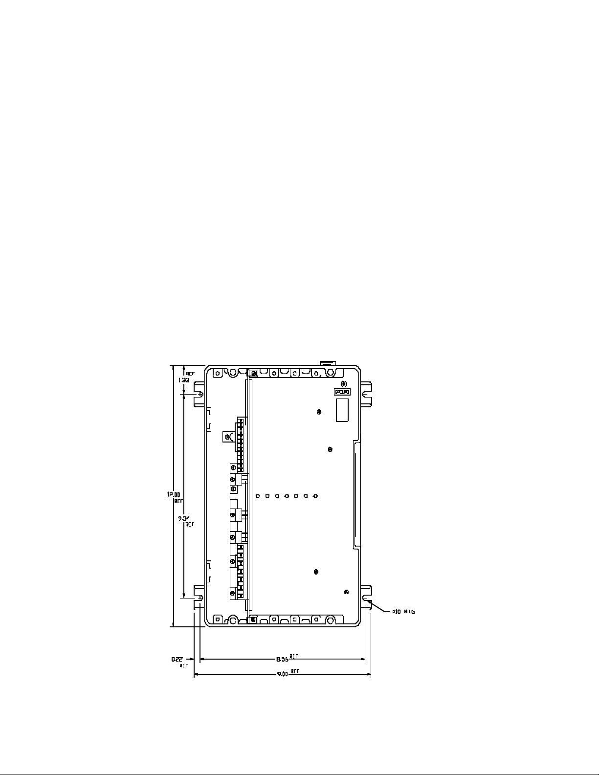
1. Mount the controller. Mounting dimensions are shown in Figure 1, below.
2. Install conduit and connect the power wiring to Terminals L1, L2, A1 (+), A2 (-), F+ and F-. Be sure to
observe Installation Guidelines 5 and 8 on pages 4 and 5. If half-wave shunt field voltage is desired, connect one of the motor shunt field leads to Terminal F/2 (see Table 14 on Page 37).
NOTE: Low inductance motors require a full-wave field to prevent current instability.
3. If the controller contains any options that require external wiring, follow the wiring instructions in the
instruction sheet supplied with the option.
4. If remote operator control wiring and/or signal wiring is required, connect the controller as shown in the
appropriate connection diagram (Figures 4 through 18). Figures 4 through 9 show operator control connections, and Figures 10 through 18 show signal connections.
5. Set the DIP Switch (S3) as shown in the appropriate connection diagram. See Figure 22 (page 43) or Figure 23 (page 44), as applicable, for the location of DIP Switch S3. Also refer to Table 13, “DIP Switch Settings,” page 36.
6. Install the controller cover, if used.
FIGURE 1. CONTROLLER MOUNTING DIMENSIONS, MODELS 2601 AND 2602
6
Page 12

BOOK0795-F
MODELS 2611 AND 2612
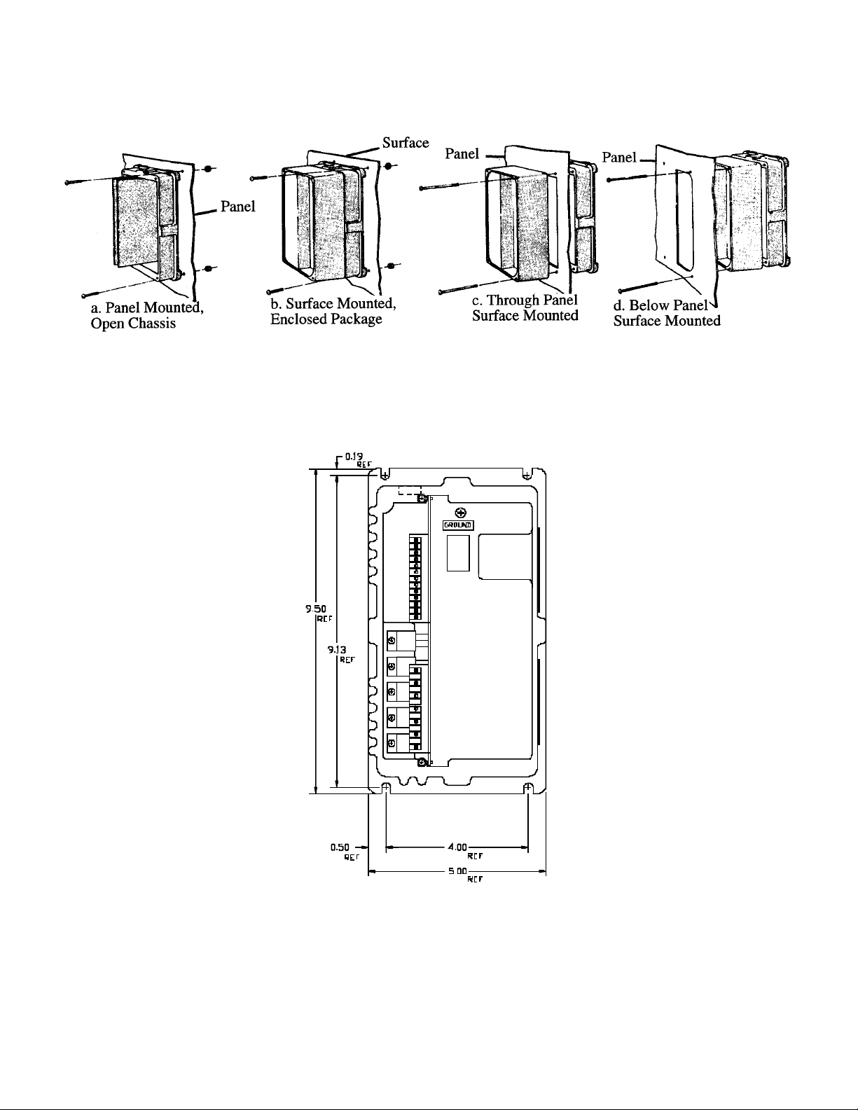
1. The controller may be surfaced mounted or panel mounted as shown in Figure 2, page 8. Mount the con-
troller. Mounting dimensions are shown in Figure 3, page 8.
2. Conduit entry is made by punching out the knockout at the top or bottom of the controller base. To prevent
component damage from knockout fragments, apply masking tape to the inside of the knockout before
punching.
3. Connect the power wiring to Terminals L1, L2, A1 (+), A2 (-), F+ and F-. Be sure to observe Installation
Guidelines 5 and 8 on pages 4 and 5. If half-wave shunt field voltage is desired, connect one of the motor
shunt field leads to Terminal F/2 (see Table 14 on Page 37).
NOTE: Low inductance motors require a full-wave field to prevent current instability.
4. If the controller contains any options that require external wiring, follow the wiring instructions in the
instruction sheet supplied with the option.
5. If remote operator control wiring and/or signal wiring is required, connect the controller as shown in the
appropriate connection diagram (Figures 4 through 18). Figures 4 through 9 show operator control connections, and Figures 10 through 18 show signal connections.
6. Set the DIP Switch (S3) as shown in the appropriate connection diagram. See Figure 22 (page 43) or Fig-
ure 23 (page 44), as applicable, for the location of DIP Switch S3. Also refer to Table 13, “DIP Switch Settings,” page 36.
7. Install the controller cover, if used.
7
Page 13
BOOK0795-F
FIGURE 2. CONTROLLER MOUNTING CONFIGURATIONS, MODELS 2611 AND 2612
FIGURE 3. CONTROLLER MOUNTING DIMENSIONS, MODELS 2611 AND 2612
8
Page 14
BOOK0795-F
FIGURE 4. LOGIC CONNECTION DIAGRAM, RUN-STOP-JOG SWITCH, 1/6 - 2 HP
FIGURE 5. LOGIC CONNECTION DIAGRAM, FORWARD-REVERSE SWITCH AND RUN-STOP-JOG
SWITCH, 1/6 - 2 HP
9
Page 15
BOOK0795-F
FIGURE 6. LOGIC CONNECTION DIAGRAM, RUN-STOP PUSHBUTTONS AND RUN-JOG SWITCH,
1/6 - 5 HP
FIGURE 7. LOGIC CONNECTION DIAGRAM, OPTIONAL ARMATURE CONTACTOR REVERSING
USING SWITCHES, 1/6 - 5 HP
10
Page 16
BOOK0795-F
FIGURE 8. LOGIC CONNECTION DIAGRAM, OPTIONAL ARMATURE CONTACTOR REVERSING
USING PUSHBUTTONS AND RUN-JOG SWITCH, 1/6 - 5 HP
FIGURE 9. LOGIC CONNECTION DIAGRAM, LINE STARTING WITH MOTOR SPEED POTENTIOME-
TER, 1/6 - 5 HP
11
Page 17

BOOK0795-F
FIGURE 10. SIGNAL CONNECTION DIAGRAM, MOTOR SPEED POTENTIOMETER
FIGURE 11. SIGNAL CONNECTION DIAGRAM, TACHOMETER FEEDBACK
FIGURE 12. SIGNAL CONNECTION DIAGRAM, CURRENT (TORQUE) REFERENCE POTENTIOMETER
12
Page 18

BOOK0795-F
FIGURE 13. SIGNAL CONNECTION DIAGRAM, LINE STARTING WITHOUT A MOTOR SPEED
POTENTIOMETER
FIGURE 14. SIGNAL CONNECTION DIAGRAM, 4 - 20 mA INTERFACE
FIGURE 15. SIGNAL CONNECTION DIAGRAM, 2-WIRE TRANSDUCER
13
Page 19

BOOK0795-F
FIGURE 16. SIGNAL CONNECTION DIAGRAM, 4 - 20 mA TRANSDUCER WITH MANUAL/AUTO
SWITCH
*
TRANSDUCER CURRENT
RANGE
1 - 5 mA 1,000 Ohms, 0.25W, ± 1%
2 - 10 mA 499 Ohms, 0.25W, ±1%
4 - 20 mA 249 Ohms, 0.25W, ±1%
10 - 50 mA 100 Ohms, 0.50W, ±1%
FIGURE 17. SIGNAL CONNECTION DIAGRAM, TRANSDUCER WITH EXTERNAL BURDEN RESISTOR
EXTERNAL BURDEN
*
RESISTOR
FIGURE 18. SIGNAL CONNECTION DIAGRAM, 0 - 10 VDC EXTERNAL SPEED REFERENCE SIGNAL
14
Page 20

BOOK0795-F
INITIAL STARTUP
1. Open the controller cover (if used) by removing the four cover screws.
2. Be familiar with all options installed in the controller by reviewing the instruction sheets supplied with the
options.
3. Be sure all wiring is correct and all wiring terminations are tightened securely.
4. Be sure the controller is calibrated correctly. See steps 4 and 5 under “Installing The Controller” on page 5.
5. Be sure the AC supply voltage to the controller agrees with the controller data label.
6. The potentiometers in the controller are factory adjusted as shown in Table 4. These settings will provide
satisfactory operation for most applications. If different settings are required, refer to “Adjustment Instructions” starting on page 21.
TABLE 4. INITIAL POTENTIOMETER SETTINGS
POTENTIOMETER SETTING DESCRIPTION
ACCEL 2/3 Turn Clockwise 8 Seconds
CUR LMT Fully Clockwise (100%) 150% Load
DECEL 2/3 Turn Clockwise 8 Seconds
IR/TACH Fully Counterclockwise (0%) 0% Boost
MAX SPD 3/4 Turn Clockwise 100% Speed
MIN SPD (Offset) Fully Counterclockwise (0%) 0% Speed
7. If the controller has a cover, place it on the controller and secure it with the four cover screws.
8. Turn-on the AC supply to the controller.
9. Check motor rotation, as follows:
a. If a MOTOR SPEED potentiometer is used, turn it fully counterclockwise. If an external signal is used
for the speed reference, set it at minimum.
b. If a RUN-STOP-JOG switch is used, place it in RUN position. Otherwise, initiate a Run command.
c. Turn the MOTOR SPEED potentiometer clockwise or increase the speed reference signal, as applica-
ble. To stop the motor, place the switch in STOP position or initiate a Stop command, as applicable.
If the motor rotates in the wrong direction, turn-off the AC supply to the controller, and then interchange
the motor armature leads at the motor connection box or at the controller terminal board.
10. Refer to Section III, “Operation” for operating instructions.
15
Page 21

BOOK0795-F
Blank Page
16
Page 22

BOOK0795-F
SECTION III
OPERATION
POWER ON/OFF
To energize the drive, turn-on the AC supply voltage to the controller. When this occurs, the motor shunt
field energizes with rated field voltage, and potentially hazardous voltage is present at the motor armature terminals. These voltages can cause electric shock resulting in personal injury or loss of life.
If the AC supply is interrupted, and the controller is not set up for line starting, the motor will not restart
when the AC supply is restored until the controller is reset by initiating a Stop command and then a Start command.
If the controller is set up for line starting, and the AC supply is interrupted, the motor will restart when the AC supply is restored, provided the external AC line contactor is pulled in.
RUN
If a RUN-STOP-JOG switch is used, place the switch in RUN position. Otherwise, initiate a Run command.
A Run command will accelerate the motor to the setting of the MOTOR SPEED potentiometer or external speed
reference signal, as applicable. The rate of acceleration is preset by the ACCEL potentiometer on the controller
control board.
STOP
If a RUN-STOP-JOG switch is used, place the switch in STOP position. Otherwise, initiate a Stop command.
A Stop command will stop the motor at a rate proportional to the stopping rate of the motor load.
If the controller has dynamic braking, the motor stopping time will be reduced. Dynamic braking provides
exponential rate braking of the motor armature, which occurs when the circuit is opened between the controller and
the motor armature, and one or more resistors connect across the motor armature.
The dynamic braking resistors provide initial braking torque as shown in Table 5.
TABLE 5. DYNAMIC BRAKING CHARACTERISTICS
COMPONENT MODEL
2601
2602
BRAKING TORQUE (%)
STOPS PER MINUTE
a. HIGH INERTIA LOADS MAY EXTEND BRAKING TIME AND CAUSE THE WATTAGE RATING OF THE DYNAMIC
BRAKING RESISTORS TO BE EXCEEDED.
2612
2611
2601
2602
2612
2611
RATED
VOLTAGE
115V 300 215 170 110 75 60 NA NA NA NA
230V NA NA NA 400 320 220 145 105 85 96
115V 180 129 103 66 44 34 NA NA NA NA
230V NA NA 400 278 190 130 88 62 NA NA
115V 9 6 5 5 4 4 NA NA NA NA
230V NA NA NA 5 4 4 3 3 2 2
115V 15 12 11 8 6 2 NA NA NA NA
230V NA NA 12 8 6 1 1 1 NA NA
1/6 1/4 1/3 1/2 3/4 1 1-1/2 2 3 5
RATED HORSEPOWER
a
17
Page 23

BOOK0795-F
An antiplug feature is included with optional Armature Contactor Reversing With Dynamic Braking (Option
1004). This feature prevents restarting the motor before the motor has braked to a stop.
SPEED CONTROL
Motor speed is directly proportional to the setting of the MOTOR SPEED potentiometer or the magnitude of
an external speed reference signal, as applicable. This potentiometer or the speed reference signal may be adjusted
while the motor is running or may be preset before the motor is started.
The rates of acceleration and deceleration are preset by the ACCEL and DECEL potentiometers, respectively, located on the controller control board.
Maximum speed and minimum speed (or offset) are preset by the MAX SPD and MIN SPD potentiometers,
respectively, located on the control board.
JOG
If a RUN-STOP-JOG switch is used, place the switch in JOG position. Otherwise initiate a Jog command.
Jog is momentary, causing motor rotation only while the switch is held in JOG position or while a Jog command is
active. Release the switch to stop the motor.
Normally, jog speed is directly proportional to the setting of the MOTOR SPEED potentiometer. If a separate JOG SPEED potentiometer is used, jog speed will be directly proportional to the setting of the JOG SPEED
potentiometer.
REVERSE
To reverse motor rotation on controllers with reversing capabilities, initiate a Stop function and then initiate
a reversing command. The motor will then accelerate to the setting of the MOTOR SPEED potentiometer or external speed reference signal, as applicable. Forward and reverse speed ranges are identical.
If a FWD-REV switch is used, it must have a center position interlock, which requires a momentary relaxation of pressure before the opposite position can be engaged. The center position causes a Stop command and
allows time for the motor to stop before a Reverse command is initiated. If a Reverse command is initiated while
the motor is rotating, motor and controller damage may occur.
If Option 1004 (Armature Contactor Reversing With Dynamic Braking) is installed, an antiplug feature prevents reversing the motor before the motor has stopped.
INOPERATIVE MOTOR
If the motor stops and/or won’t start, turn-off the AC supply to the controller, remove the controller cover (if
used), and check the AC line fuse on the controller control board. For the location of the fuse, see Figure 22 (page
43) or Figure 23 (page 44), as applicable. If the fuse is blown, refer to the Troubleshooting Table (Table 6).
18
Page 24

BOOK0795-F
If the fuse is not blown, the internal overload monitor may have shut down the controller. The overload monitor will shut down the controller if the motor armature current exceeds 120% of rated for a length of time of continuous operation. The length of time is determined by the amount of the overload. If the overload monitor trips,
reset the controller by initiating a Stop command, removing the overload, and then initiating a Run command to
restart. Repeated shutdown indicates an overload condition (mechanical or electrical) which must be removed.
Refer to the Troubleshooting Table (Table 6).
19
Page 25

BOOK0795-F
Blank Page
20
Page 26

BOOK0795-F
SECTION IV
MAINTENANCE AND REPAIR
GENERAL
1. Keep the controller dry and free of dust, dirt, and debris. No parts require periodic replacement.
2. Periodically turn-off the AC line supply to the controller and check all wire terminations to be sure they are
tight.
3. Visually check components for damage due to overheating or breakage. All damaged and/or faulty components must be replaced for satisfactory operation.
4. Maintain the motor according to maintenance instructions supplied by the motor manufacturer.
ADJUSTMENT INSTRUCTIONS
ACCELERATION
1. Set the MOTOR SPEED potentiometer at 100% or the external speed reference signal at maximum, as
applicable.
2. Initiate a Run command and observe the time required for the motor to reach maximum speed.
3. Adjust the ACCEL potentiometer for the desired rate. Full clockwise rotation is the fastest acceleration
(0.2 second), and full counterclockwise rotation is the slowest acceleration (30 seconds).
DECELERATION
1. With the motor running at maximum speed, quickly reset the MOTOR SPEED potentiometer to zero, or
quickly decrease the speed reference signal to minimum, as applicable, and observe the time required for
the motor to reach minimum speed.
2. Adjust the DECEL potentiometer for the desired rate. Full clockwise rotation is the fastest deceleration
(0.2 second), and full counterclockwise rotation is the slowest deceleration (30 seconds).
IR COMPENSATION
IR compensation is used only when the controller is programmed for armature feedback. The IR/TACH
potentiometer is factory set at zero (full counterclockwise rotation) for satisfactory operation with most motors. If
improved speed regulation is desired, readjust IR compensation as follows:
21
Page 27

BOOK0795-F
1. Be sure Segments 2 and 3 of DIP Switch S3 are in ON (Closed) position.
2. If the motor is shunt-wound, run it at rated base speed. If the motor is a permanent-magnet type, run it
about 1/3 speed.
3. Turn the IR/TACH potentiometer clockwise slowly until motor speed becomes unstable. Then turn the
potentiometer counterclockwise until motor speed stabilizes.
MAXIMUM SPEED (ARMATURE FEEDBACK)
The MAX SPD potentiometer adjusts maximum speed by setting maximum armature voltage. The voltage
range is from 50% to 100% of rated armature voltage. If the controller is programmed for tachometer feedback, the
MAX SPD potentiometer sets the armature backup voltage.
1. Be sure Segments 2 and 3 of DIP Switch S3 are in ON (Closed) position.
2. Turn the MAX SPD potentiometer fully clockwise (100%). This setting provides 90 VDC armature voltage with a 115 VAC line, or 180 VDC armature voltage with a 230 VAC line.
3. Run the motor at maximum speed, and turn the MAX SPD potentiometer counterclockwise for the desired
maximum speed.
NOTE: If the MAX SPD potentiometer is turned too far counterclockwise, speed instability may occur.
MAXIMUM SPEED (TACHOMETER FEEDBACK)
Tachometer feedback provides speed regulation characteristics as shown in Table 12, page 35. However, these
characteristics are based on the use of Fincor Electronics cataloged motors and generators. Regulation characteristics and drive performance cannot be guaranteed with motors and/or tachometer generators that have not been evaluated. For example, some tachometer generators with low voltage/RPM ratios may not provide adequate feedback
signal levels at low speed.
1. Be sure Segments 2 and 3 of DIP Switch S3 are in OFF (Open) position.
2. Set Segment 1 of DIP Switch S3 for the expected tachometer generator speed at maximum speed, as follows:
SEGMENT 1 POSITION TACH VOLTAGE
ON (Closed) 8V - 30V
OFF (Open) 31V - 175V
3. Turn the IR/TACH potentiometer fully counterclockwise (0%). This setting provides maximum motor
speed.
4. Be sure the MAX SPD potentiometer has been adjusted correctly.
22
Page 28

BOOK0795-F
5. Run the motor at maximum speed, and start turning the IR/TACH potentiometer clockwise until motor
speed increases above desired speed. Continue turning the potentiometer clockwise until motor speed
decreases to desired speed.
MINIMUM SPEED
1. Be sure Segment 6 of DIP Switch S3 is in ON (Closed) position.
2. Turn the MIN SPD potentiometer fully counterclockwise (0%) for zero speed.
3. Set the MOTOR SPEED potentiometer at 0% or the external speed reference signal at minimum, as appli-
cable.
4. Initiate a Run command and adjust the MIN SPD potentiometer for the desired minimum speed (adjustable
from 0 to 40% of motor base speed).
OFFSET
An offset adjustment is desirable when a 4 mA to 20 mA speed reference signal is used. The MIN SPD
potentiometer compensates for the 4 mA offset.
1. Be sure Segment 6 of DIP Switch S3 is in OFF (Open) position, and a wire jumper connects between TB2-
1 and TB2-3.
2. Set the speed reference signal at 4 mA and initiate a Run command.
3. Adjust the MIN SPD potentiometer as desired.
NOTE: The MIN SPD potentiometer may be ineffective between 50% and 100%.
CURRENT LIMIT
1. Turn the CUR LMT potentiometer fully clockwise (100%) to limit motor armature current at 150% of
rated.
2. Turn the CUR LMT potentiometer counterclockwise to reduce maximum motor armature current.
NOTES: a. An LED glows red on the controller control board when motor armature current is being lim-
ited.
b. An external 5K ohm Current (Torque) Limit potentiometer can be used as shown in Figure 12
on page 12. Segment 5 of DIP Switch S3 must be in OFF (Open) position if an external Current (Torque) Limit potentiometer is desired.
23
Page 29

BOOK0795-F
TROUBLESHOOTING
TABLE 6. TROUBLESHOOTING
INDICATION POSSIBLE CAUSE CORRECTIVE ACTION
1. Motor won’t start
(See “Inoperative
Motor,” page 18.)
AC line open
Operator controls inoperative or connected incorrectly
Open circuit between Connectors E1
and E2 in 1/6 - 3 HP controllers
Controller not reset
Line Voltage Selection Jumper J1 in
wrong position
Controller not enabled
Loss of speed reference signal
Controller not adjusted correctly
Be sure rated AC line voltage is applied to the
controller.
Repair accordingly.
A wire jumper or switch must connect E1 to
E2.
Initiate a Stop command and then a Start command.
See Step 5 on page 5 under, “Installing The
Controller.”
Be sure +24 VDC is applied to Terminal TB2-
8.
Check for 0 - 10 VDC, 4 - 20 mA, or 0 - 5
VDC speed reference signal, as applicable.
Turn the ACCEL and CUR LIM potentiometers fully clockwise (100%).
DIP Switch S3 not set correctly See Table 13, page 36.
2. Controller fuse blows
when AC line power is
applied to the controller
Contd on next page
Open shunt field winding or wiring to
the motor shunt field, causing loss of
a
torque
Check the motor shunt field and associated
circuitry for a loose connection or a broken
wire. Repair accordingly.
Motor failure Repair or replace the motor.
Control board failure Replace the control board.
Wiring faulty or incorrect
Circuit, component, or wiring
grounded
Check all external wiring terminating in the
controller. Correct accordingly.
Remove ground fault.
Two or more SCR’s shorted Replace shorted SCR’s or the control board.
Varistor RV1 shorted Replace RV1 or the control board.
Shunt Field Bridge BR1 shorted
a
Replace BR1 or the control board.
Motor shunt field shorted or groundedaRepair or replace the motor.
Control board failure Replace the control board.
24
Page 30

BOOK0795-F
TABLE 6. TROUBLESHOOTING
INDICATION POSSIBLE CAUSE CORRECTIVE ACTION
3. Controller fuse blows
when a Start command is
initiated
4. Controller fuse blows
while the motor is running
One or more SCR‘s or Diode D1
shorted
Replace shorted devices or the control board.
Motor shorted or grounded Repair or replace the motor.
Control board failure causing SCR’s to
turn-on fully
Replace the control board.
Check shunt field current.a Low shunt field
current causes excessive armature current. If
field current is adequate, check for a mechani-
Motor overloaded
cal overload. If the unloaded motor shaft does
not rotate freely, check motor bearings. Also
check for a shorted motor armature. Motor
overload can also be caused by incorrect gear
ratio. Correct accordingly.
Loose or corroded connection. Wiring
faulty, incorrect, or grounded
Check all terminals, connections, and wiring
between the line, controller, and motor.
Motor shorted or grounded Repair or replace the motor.
One or more SCR‘s or Diode D1
breaking down (shorting intermit-
Replace shorted devices or the control board.
tently)
5. Minimum speed excessive
6. Maximum speed
excessive
Contd on next page
Control board failure causing SCR
false firing or misfiring
Minimum speed not adjusted correctly
Replace the control board.
Turn the MIN SPD potentiometer counterclockwise.
Control board failure Replace the control board.
Maximum speed set too high
Turn the MAX SPD potentiometer counterclockwise.
Controller not calibrated correctly Refer to Steps 4 and 5 on page 5.
Open shunt field winding or wiring to
the motor shunt field
Motor field demagnetized
a
b
Check the motor shunt field and associated
circuitry for a loose connection or a broken
wire. Repair accordingly.
Replace the motor.
25
Page 31

BOOK0795-F
TABLE 6. TROUBLESHOOTING
INDICATION POSSIBLE CAUSE CORRECTIVE ACTION
7. Motor won’t reach top
speed
Low line voltage
Check for rated line voltage, ±10%, on the
controller line terminals.
Check shunt field current.a Low shunt field
current causes excessive armature current. If
field current is adequate, check for a mechani-
Motor overloaded
cal overload. If the unloaded motor shaft does
not rotate freely, check motor bearings. Also
check for a shorted motor armature. Motor
overload can also be caused by incorrect gear
ratio. Correct accordingly.
Maximum speed set too low Turn the MAX SPD potentiometer clockwise.
Current limit set too low Turn the CUR LMT potentiometer clockwise.
Current Scaling Jumper J4 in wrong
position
Motor field demagnetized
b
See Step 4 and Table 3, page 5.
Replace the motor.
Control board failure Replace the control board.
Observe line voltage with a voltmeter or oscil-
AC line voltage fluctuating
loscope. If fluctuations occur, correct condition accordingly.
8. Unstable speed
Contd on next page
Loose or corroded connection. Wiring
faulty, incorrect, or grounded
Oscillating load connected to the
motor
Voltage Selection Jumpers J1, J2, J3 in
wrong position
IR compensation not adjusted correctly
Maximum speed not adjusted correctly
Motor faulty
Tachometer generator or coupling
faulty (if used)
Check all terminals, connections, and wiring
between the line, operator controls, controller,
and motor.
Stabilize the load. Turning the IR/TACH
potentiometer counterclockwise may minimize oscillations.
See Step 5 on page 5 under, “Installing The
Controller.”
See the IR Compensation adjustment instructions on page 21.
See the Maximum Speed (Armature Feedback) adjustment instructions on page 22.
Check motor brushes. Replace if needed.
Repair or replace the motor.
Repair accordingly.
26
Page 32

TABLE 6. TROUBLESHOOTING
INDICATION POSSIBLE CAUSE CORRECTIVE ACTION
Check shunt field current.a Low shunt field
current causes excessive armature current. If
field current is adequate, check for a mechani-
9. Line and motor armature current excessive
Motor overloaded
cal overload. If the unloaded motor shaft does
not rotate freely, check motor bearings. Also
check for a shorted motor armature. Motor
overload can also be caused by incorrect gear
ratio. Correct accordingly.
BOOK0795-F
10. Shunt field current a
too low
11. Shunt field current a
too high
12. Motor thermal guard
tripped (if used)
Open shunt field winding or wiring to
the motor shunt field
Shunt field connected for incorrect
voltage
Check the motor shunt field and associated
circuitry for a loose connection or a broken
wire. Repair accordingly.
Check motor rating and refer to Table 14,
page 37.
Shunt Field Bridge BR1 failure Replace BR1 or the control board.
Shunt field connected for incorrect
voltage
Check motor rating and refer to Table 14,
page 37.
Measure the shunt field resistance and com-
Shunt field windings shorted
pare with the motor rating. Repair or replace
the motor.
Ventilation insufficient
Remove dirt, dust, and debris from the motor
intake and exhaust screens.
Excessive motor load at low speed Reduce the load or increase the speed.
Line and motor armature current
excessive
See Indication 9.
Motor overheating from friction Check for misalignment. Realign the motor.
Shorted motor windings or faulty bearings
Contd on next page
a. Does not apply to permanent-magnet motors.
b. Does not apply to shunt-wound motors.
Repair or replace the motor.
27
Page 33

BOOK0795-F
Blank Page
28
Page 34

SECTION V
OPTIONS
Options are available for Series 2600/2610 Controllers which increase the functional use of the basic control-
ler. Table 7 (page 22) lists all available options and allowable option combinations.
Options can be added to the basic controller at any time. Each option consists of all required components,
mounting hardware, and instruction sheet.
BOOK0795-F
29
Page 35

BOOK0795-F
TABLE 7. ALLOWABLE OPTION COMBINATIONS
OPTION TYPE
Enclosure Options - Choice of any or all
within this group. May be combined with
options from any other groups.
Options Used To Convert Open Chassis
Units Into Enclosed Package Controllers - Choice of one within this group. May
be combined with options from any other
groups.
Power Options
Input Signal Options - Choice of one
within this group unless Option 1037 is
selected. May be combined with options
from any other groups except Group F.
Option 1775 is required for all options in
this group.
Feedback Options - Choice of one within
this group unless Option 1037 is selected.
May be combined with options from any
other groups except Group F. Option 1775
is required for all options in this group.
Input And Feedback Options - May be
combined with options from any other
groups except Groups D and E.
External Options - Choice of any or all
within this group
Miscellaneous Options - Choice of any or
all within this group when mounted externally. Choice of one when mounted in a
Model 2601 or 2602. May be combined
with options from any other groups.
a. XK = Factory Installed Or Field Kit
K = Field Kit
P = Plug-In Option
OPTION
GROUP
A 1638 XK Hinge, Enclosure Cover (Models 2601 And 2602 Only)
A 1170A XK
B 1639 XK Cover Assembly, Blank Type P0
B 1639C XK Cover Assembly, Type P1
B 1639E XK Cover Assembly, Type P2
B 1639G XK Cover Assembly, Type P3
C 1010 XK Circuit Breaker - Two Pole (Model 2601 Only)
C 1014 XK AC Line Switch (Model 2602 Only)
C 1004 XK
D 1775 XK Interface, Signal Options
D 1037 XK, P Input, External Interface
D 1049 XK, P Follower, External DC Signal
D 1050 XK, P Follower, External AC Signal
D 1050A XK, P Follower, AC Current Transducer
D 1051 XK, P Follower, MIRC
D 1055 XK, P Follower, AC Or DC Tachometer Generator
D 1057A XK, P Follower, Digital Pulse Generator
D 1059 XK, P Precision Reference
E 1775 XK Interface, Signal Options
E 1037 XK, P Feedback, External Interface
E 1061C XK, P Feedback, AC Or DC Tachometer Generator
E 1061F XK, P Feedback, AC Or DC Tachometer Generator With Tach Loss
E 1062A XK, P Feedback, Digital Pulse Generator
E 1064 XK, P Torque (Current) Limit Control
E 1190 XK, P Torque Taper
F 1064A XK Follower, Current Regulator
F 1191 XK Centerwind Torque Control
F 1220 XK Constant Velocity Winder
G 1120 K Operator Control Station - Remote
G 1120A K Motor Speed Potentiometer, Ten-Turn With Analog Dial
G 1120B K Motor Speed Potentiometer, One-Turn
G 1120C K Motor Speed Potentiometer, Ten-Turn With Digital Dial
G 1022 K Jog, Toggle Switch Selection
G 1058A K Follower/Manual Mode Select Switch
G 1037A K Input-Feedback Adapter, External - One Position
G 1166 K Equipment Manual
H 1047 XK Controlled (Ramp) Stop
H 1081B XK Current (Torque) Monitor
H 1015 XK Magnetic Control Interface (115V)
OPTION
NUMBER
OPTION
CODE
a
Fan Assembly (5 HP Units Only) (Required When Enclosed
Model 2602 Is Operated At 5 HP Rating)
Armature Contactor Reversing With Dynamic Braking (May Be
Combined With All Options In This Group)
OPTION
30
Page 36

SECTION VI
PARTS LIST
TABLE 8. PARTS LIST, SERIES 2600/2610 CONTROLLERS
FINCOR PART NUMBER
BOOK0795-F
PART RATING
Control Board NA 106105702 106109601 106105701 106105702
30A, 600V (ATM-30) 3002396 NA 3002396 3002396
Fuse, Line
60A, 300V (SC-60) NA 3002526 NA NA
55A, 800V 3302231 NA NA 3302231
SCR
Silicon Rectifier
(Freewheeling Diode)
65A, 600V NA 3302223 NA NA
15A, 600V NA NA 3302201 NA
15A, 600V NA NA 3303207 NA
24A, 600V 3303292 3303292 NA 3303292
MODEL
2601
MODEL
2602
MODEL
2611
MODEL
2612
31
Page 37

BOOK0795-F
Blank Page
32
Page 38

BOOK0795-F
SECTION VII
RATINGS AND SPECIFICATIONS
RATINGS
1. Current/Torque Reference Potentiometer. . . . . . . . . . . . . . . . . . . . . . . . . . . . . . . . . . . . . . . . . 5K Ohms, 1/2W
2. Duty. . . . . . . . . . . . . . . . . . . . . . . . . . . . . . . . . . . . . . . . . . . . . . . . . . . . . . . . . . . . . . . . . . . . . . . . . . . Continuous
3. Horsepower Range. . . . . . . . . . . . . . . . . . . . . . . . . . . . . . . . . . . . . . . . . . . . . . 1/6 - 5 HP (See Table 1, Page 1)
4. Line Fuse Interrupting Capacity. . . . . . . . . . . . . . . . . . . . . . . . . . . . . . . . . . . . . . . . . . . . . . . 100,000 Amperes
5. Line Power. . . . . . . . . . . . . . . . . . . . . . . . . . . . . . . . . . . . . . . . . . . . 115V Or 230V, Single-Phase, 50 Or 60 Hz
6. Motor Speed Potentiometer. . . . . . . . . . . . . . . . . . . . . . . . . . . . . . . . . . . . . . . . . . . . . . . . . . . . 5K Ohms, 1/2W
7. Overload Capacity, Armature Circuit. . . . . . . . . . . . . . . . . . . . . . . . . . . . . . . . . . . . . . . . . . 150% For 1 Minute
8. Service Factor. . . . . . . . . . . . . . . . . . . . . . . . . . . . . . . . . . . . . . . . . . . . . . . . . . . . . . . . . . . . . . . . . . . . . . . . . . 1.0
TABLE 9. TYPICAL APPLICATION DATA
COMPONENT RATINGS
RATED HORSEPOWER (HP) 1/6 1/4 1/3 1/2 3/4 1 1-1/2 2 3 5
RATED KILOWATTS (kW) 0.124 0.187 0.249 0.373 0.560 0.746 1.120 1.492 2.238 3.730
115V
1-PHASE
AC INPUT
(FULL-LOAD)
DC OUTPUT
(FULL-LOAD)
FULL-LOAD TORQUE (lb-ft) with
1750 RPM Base Speed Motors
MINIMUM TRANSFORMER KVA FOR
VOLTAGE MATCHING OR ISOLATION
Line
Amps
KVA 0.48 0.58 0.71 1.00 1.40 2.00 3.00 4.00 5.00 8.00
Motor
Armature
Amps
Motor
Field
Amps
(Maximum)
Unit
230V
Unit
90V 2.0 2.8 3.5 5.4 8.1 10.5 NA NA NA NA
180V NA NA NA 2.6 3.8 5.5 8.2 11.6 15.1 25.0
Series
2600
Series
2611
Series
2612
3.9 5.0 6.0 8.7 12.4 15.8 NA NA NA NA
NA NA NA 4.2 5.9 8.8 12.6 15.8 22.0 32.0
2.0 2.0 2.0 2.0 2.0 2.0 2.0 2.0 2.0 2.0
1.0 1.0 1.0 1.0 1.0 1.0 1.0 1.0 NA NA
1.5 1.5 1.5 1.5 1.5 1.5 1.5 1.5 1.5 NA
0.5 0.75 1.0 1.5 2.2 3.0 4.5 6.0 9.0 15.0
0.5 0.75 0.75 1.0 1.5 2.0 3.0 5.0 7.5 10.0
33
Page 39

BOOK0795-F
TABLE 10. OPERATING VOLTAGES AND SIGNALS
POWER SOURCE
(Single-Phase)
115V, 50 or 60 Hz 0 - 90 50/100 0 - 5 VDC,
230V, 50 or 60 Hz 0 - 180 100/200
a. Grounded or ungrounded. Choice of one.
OUTPUT VDC SPEED
Armature Field
REFERENCE
SIGNAL
0 - 10 VDC,
4 - 20 mA
MAGNETIC
CONTROL
a
VOLTAGE
24 VDC
TABLE 11. CONTROLLER WEIGHTS
CONTROLLER MODEL WEIGHT - LBS (KG)
Rated Horsepower (HP) 1/6 - 2 3 5
2601 7.70 (3.50) NA
2602 8.20 (3.72) 8.60 (3.90)
2601A 8.50 (3.86) NA
2602A 8.90 (4.04) 9.30 (4.22)
2601P0, P1, P3 11.60 (5.26) NA
2602P0, P1, P3 12.10 (5.49) 12.50 (5.67)
2601AP0, P1, P3 12.40 (5.62) NA
2602AP0, P1, P3 12.80 (5.81) 13.20 (6.00)
2611, 2612 3.25 (1.47) NA
2611A, 2612A 3.80 (1.72) NA
2611P0, P1, P2 5.50 (2.50) NA
2611AP0, P3 6.05 (2.74) NA
OPERATING CONDITIONS
1. Altitude, Standard. . . . . . . . . . . . . . . . . . . . . . . . . . . . . . . . . . . . . . . . . . 1000 Meters (3300 Feet) Maximum.1
2. Ambient Temperature2. . . . . . . . . . . . . . . . . . . . . . . . . . . . . . . . . . . . . . . . . . . . . . . . . 0 - 40°C (32°F - 104°F)
3. Line Frequency Variation. . . . . . . . . . . . . . . . . . . . . . . . . . . . . . . . . . . . . . . . . . . . . . . . . . . . . . ± 2 Hz Of Rated
4. Line Voltage Variation. . . . . . . . . . . . . . . . . . . . . . . . . . . . . . . . . . . . . . . . . . . . . . . . . . . . . . . . . ±10% Of Rated
5. Relative Humidity. . . . . . . . . . . . . . . . . . . . . . . . . . . . . . . . . . . . . . . . . . . . . . . . . . . . . . . . 95% Noncondensing
1. Controller can be derated by 1% per 100 meters to operate at higher altitudes.
2. 55°C (131°F) maximum in enclosed areas where open-chassis controllers are mounted.
34
Page 40

BOOK0795-F
PERFORMANCE CHARACTERISTICS
1. Controlled Speed Range . . . . . . . . . . . . . . . . . . . . . . . . . . . . . . . . . . . . . . . . . . . . . . . . 0 To Motor Base Speed
2. Displacement Power Factor (Rated Speed/Rated Load). . . . . . . . . . . . . . . . . . . . . . . . . . . . . . . . . . . . . . . 87%
3. Efficiency (Rated Speed/Rated Load)
a. Controller Only. . . . . . . . . . . . . . . . . . . . . . . . . . . . . . . . . . . . . . . . . . . . . . . . . . . . . . . . . . . . . . . . . . . . . 98%
b. Controller With Motor, Typical. . . . . . . . . . . . . . . . . . . . . . . . . . . . . . . . . . . . . . . . . . . . . . . . . . . . . . . 85%
4. Speed Regulation. . . . . . . . . Regulation percentages are of motor base speed under steady-state conditions
TABLE 12. SPEED REGULATION CHARACTERISTICS
VARIABLE
REGULATION
METHOD
Load
Change
(95%)
Line
Voltage
(±10%)
Field
Heating
a
(Cold/Normal)
Temperature
(±10°C)
Speed
Range
Standard Voltage
Feedback with IR
Compensation
Optional Speed
(Tach) Feedback
(Option 1061C)
with Sigmation or
5PY DC Tach
a. With Precision Reference (Option 1059), regulation due to ±10% line voltage
change is ±0.1%.
b. Speed regulation characteristics are based on the use of Fincor Electronics cataloged motors and tachometer generators. Regulation characteristics cannot be guaranteed with motors and/or tachometer generators that have not been evaluated.
b
2% ±1% 5 - 12% ±2% 50:1
0.5% ±1% 0.2% ±2% 200:1
ADJUSTMENTS
1. Acceleration, Linear. . . . . . . . . . . . . . . . . . . . . . . . . . . . . . . . . . . . . . . . . . . . . . . . . . . . . . . . . . 0.2 - 30 Seconds
2. Deceleration, Linear. . . . . . . . . . . . . . . . . . . . . . . . . . . . . . . . . . . . . . . . . . . . . . . . . . . . . . . . . . 0.2 - 30 Seconds
3. IR (Load) Compensation. . . . . . . . . . . . . . . . . . . . . . . . . . . . . . . . . . . . . . . . . . . . . . . . . . . . . . . . 0 - 10% Boost
4. Jog Speed. . . . . . . . . . . . . . . . . . . . . . . . . . . . . . . . . . . . . . . . . . . . . . . . . . . . . . 0 - 100% Of Motor Base Speed
5. Maximum Speed. . . . . . . . . . . . . . . . . . . . . . . . . . . . . . . . . . . . . . . . . . . . . . 50% - 100% Of Motor Bas e Speed
6. Minimum Speed. . . . . . . . . . . . . . . . . . . . . . . . . . . . . . . . . . . . . . . . . . . . . . . . . . 0 - 40% Of Motor Base Speed
7. Torque (Current) Limit. . . . . . . . . . . . . . . . . . . . . . . . . . . . . . . . . . . . . . . . . . . . 0 - 150% Of Full-Load Torque
35
Page 41

BOOK0795-F
SPECIFICATIONS
1. AC LINE PROTECTION - A 100,000 ampere interrupting capacity AC line fuse provides instantaneous
protection from peak loads and fault currents. This line fuse is located inside the controller. A moldedcase, magnetic-trip circuit breaker (Option 1010) is available for Model 2601 Controllers, which provides
a manual disconnection to the controller, and also provides automatic instantaneous trip protection from a
peak load.
2. AUXILIARY CONTACT - A normally-open Form A relay contact, rated 5 ampere @115 VAC and 30
VDC, is available for external use. The relay energizes when a Run command is initiated, and de-energizes
when a Normal Stop command is initiated, the overload monitor trips, or the anti-restart circuit is activated.
3. CONTROL VOLTAGE - A transformer coupled 24 VDC power supply isolates all magnetic control
logic and operator controls from the AC power source for operator protection.
4. DIP SWITCH SETTINGS - A 7-position DIP Switch (S3) is used to program the controller for various
applications as shown in Table 13.
TABLE 13. DIP SWITCH S3 SETTINGS
SEGMENT
1
2
3
4
5
6
SEGMENT POSITION
ON
(Closed)
OFF
(Open)
DESCRIPTION
X Low voltage tachometer generator signal (8 VDC - 30 VDC)
X High voltage tachometer generator signal (31 VDC - 175 VDC)
X Armature feedback
X Tachometer feedback with armature feedback backup
X Armature feedback
X Tachometer feedback with armature feedback backup
X 4 mA - 20 mA input speed reference signal
X 0 - 5 VDC input speed reference signal
X
X
Enables the internal current limit circuit, adjustable with the CUR LMT
potentiometer.
Enables the use of an external current (torque) limit potentiometer (5K
ohm, 1/2W)
X Selects the MIN SPD potentiometer as a minimum speed adjustment
X
Selects the MIN SPD potentiometer as an offset adjustment for a 4 mA 20 mA input speed reference signal
7
X
Enables anti-restart. Prevents the controller from restarting automatically after an AC power interruption.
X Line starting. Disables anti-restart.
36
Page 42

BOOK0795-F
5. FEEDBACK - Two selectable modes of analog feedback are provided, as follows. See Table 12 (page 35)
for speed regulation characteristics.
a. Armature Feedback - Counter EMF voltage feedback with IR compensation, adjustable for individ-
ual motor characteristics.
b. DC Tachometer Feedback - The controller provides voltage scaling, and terminals for accepting the
output of a DC tachometer generator, mechanically coupled to the drive motor armature. The controller will automatically transfer to armature feedback if the tachometer signal is lost. Tachometer generators with an output of 8 VDC to 175 VDC at maximum speed may be used.
6. FIELD SUPPLY - A half-wave or full-wave shunt field supply is available as shown in Table 14.
TABLE 14. SHUNT FIELD DATA
CONTROLLER RATING
(VAC)
SHUNT FIELD VOLTAGE
(VDC)
Half-Wave Full-Wave
MOTOR SHUNT FIELD
LEAD CONNECTIONS
a
F1 F2
50 F/2 F-
115
100 F+ F-
100 F/2 F-
230
200 F+ F-
a. Low inductance motors require a full-wave field to prevent current instability.
7. ISOLATED REGULATOR - The internal DC circuits are isolated from the AC power source for opera-
tor and equipment safety, and for simplified application. The common of the input speed reference signal
may be grounded or connected without additional isolation to other drive controllers or grounded external
signal sources. This isolation eliminates line voltage to ground potentials on the motor speed potentiometer.
8. MOTOR CONTACTOR - Controller model numbers with an ‘A’ suffix, e.g., 2601A, 2611AP3, have a
DC magnetic armature contactor, which disconnects both motor armature leads from the controller. An
antiplug circuit ensures that the contactor does not make or break DC.
9. MOTOR OVERLOAD - A nonadjustable inverse time overload circuit continuously monitors motor
armature current and shuts down the controller whenever the current exceeds 120% of rated for a length of
time of continuous operation. The length of time is determined by the amount of overload.
10. POWER CONVERSION - The DC power bridge consists of four SCR’s and a freewheeling diode. Each
device is rated at least 600 PIV. The controller base forms an integral heat sink, with the power devices
electrically isolated from the base.
11. SELECTABLE CAPABILITIES - The DIP Switch (S3) allows the user to select various modes of oper-
ation, as follows:
37
Page 43

BOOK0795-F
a. External DC Signal Follower - The controller will operate with an external 0 - 5 VDC, 0 - 10 VDC,
b. Line Starting - By placing S3-7 in OFF (Open) position, the ‘anti-restart’ feature will be disabled, and
c. Tachometer Feedback - To select tachometer feedback with armature feedback backup, place S3-2
or 4 - 20 mA speed reference signal. The signal may be grounded or not grounded, isolated or not isolated. Motor speed will be proportional to the signal.
0 - 5 VDC - Place S3-4 in OFF (Open) position, and connect the signal to TB2-6.
0 - 10 VDC - Place S3-4 and S3-6 in ON (Closed) position, and connect the signal to TB2-2.
4 - 20 mA - Place S3-4 in ON (Closed) position, and connect the signal to TB2-6 (+) and TB2-5 (-). To
use the MIN SPD potentiometer as a 4 mA offset adjustment, place S3-6 in OFF (Open) position, and
jumper TB2-1 to TB2-3.
the controller may be started and stopped with an external AC line contactor. In addition, a wire
jumper must be connected between TB2-8 and TB2-9. If full speed operation is desired, connect
another wire jumper between TB2-2 and TB2-3.
and S3-3 in OFF (Open) position, and connect the tachometer generator signal to TB2-7 (-) and TB2-5
(+). Select the tachometer generator voltage range with S3-1, as follows:
8 VDC - 30 VDC at maximum speed, place S3-1 in ON (Closed) position.
31 VDC - 175 VDC at maximum speed, place S3-1 in OFF (Open) position.
d. Torque Regulator - The controller will function as a torque regulator when S3-5 is set to OFF (Open)
position. This allows an external potentiometer to set maximum motor torque (0 - 150% of rated).
12. STATUS INDICATOR - A bicolor LED glows red when motor armature current is being limited by the
controller current limit, and glows green when armature current is not being limited.
13. VOLTAGE TRANSIENT PROTECTION - A metal oxide suppressor (varistor) across the AC line is
combined with RC snubbers across the power bridge to limit potentially damaging high voltage spikes
from the AC power source.
38
Page 44

SECTION VIII
DRAWINGS
BOOK0795-F
39
Page 45

BOOK0795-F
C1061676
Rev. B
249
40
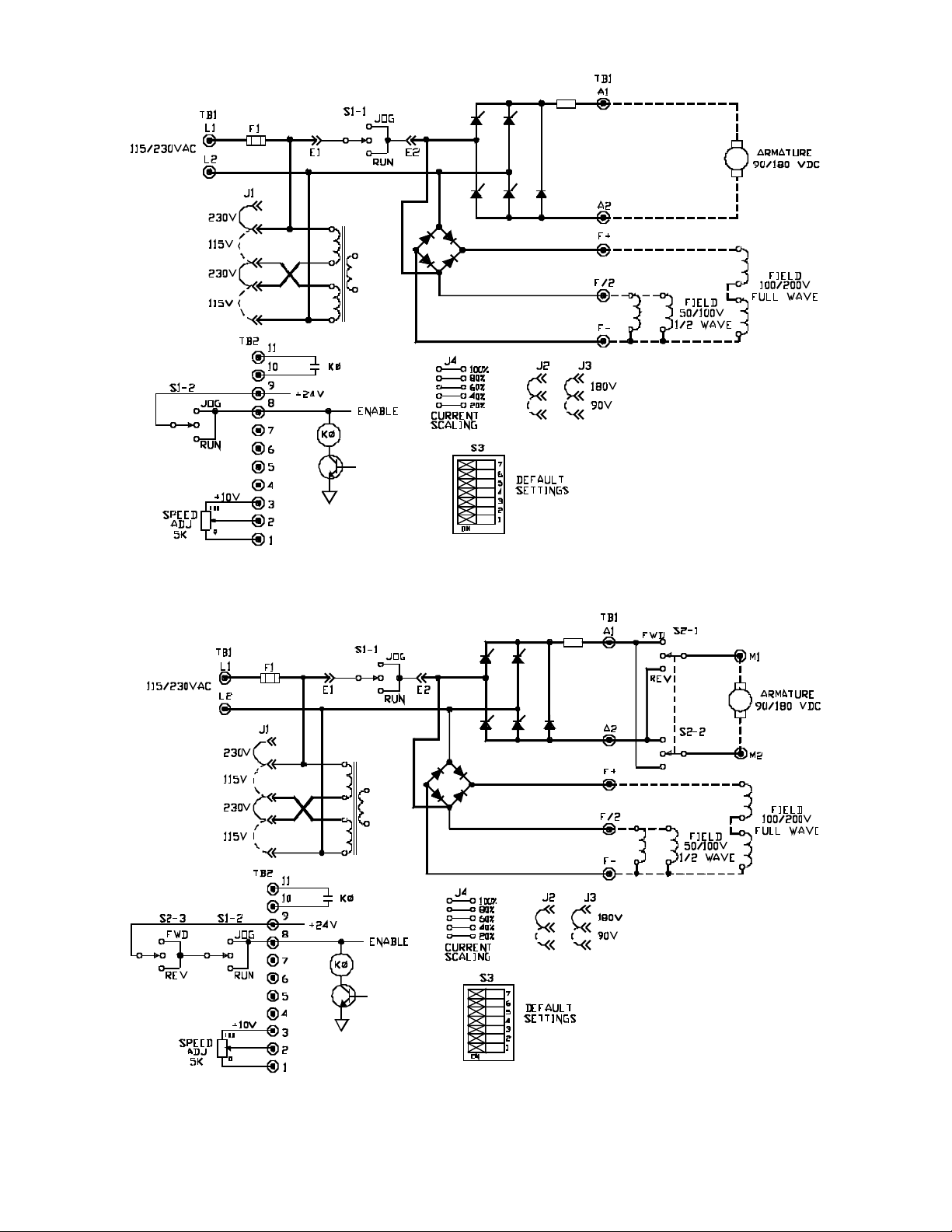
FIGURE 19. FUN C TION AL SCHEMATIC, SERIES 2600/2610
Page 46

BOOK0795-F
C1061059
Rev. D
41
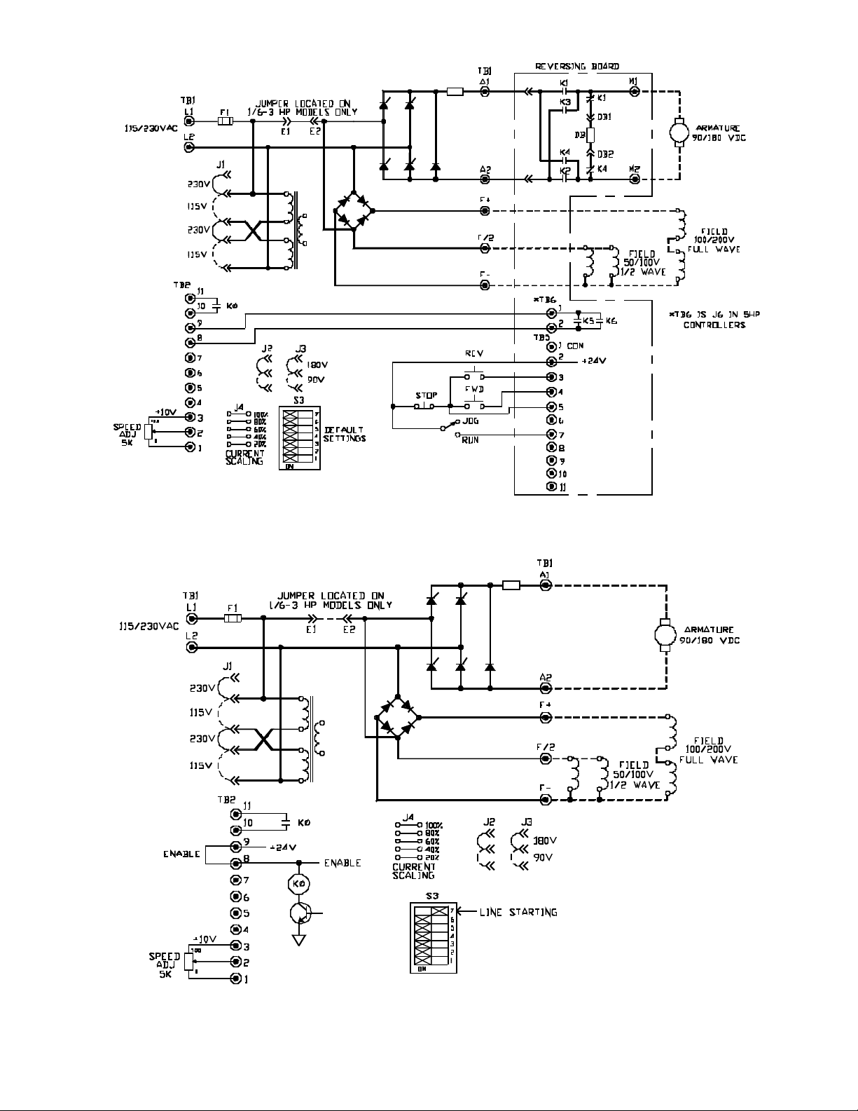
FIGURE 20. S CH E MATIC, SERIES 2600/2610, 1/6 - 3 HP
Page 47

BOOK0795-F
C1061098
Rev. E
42
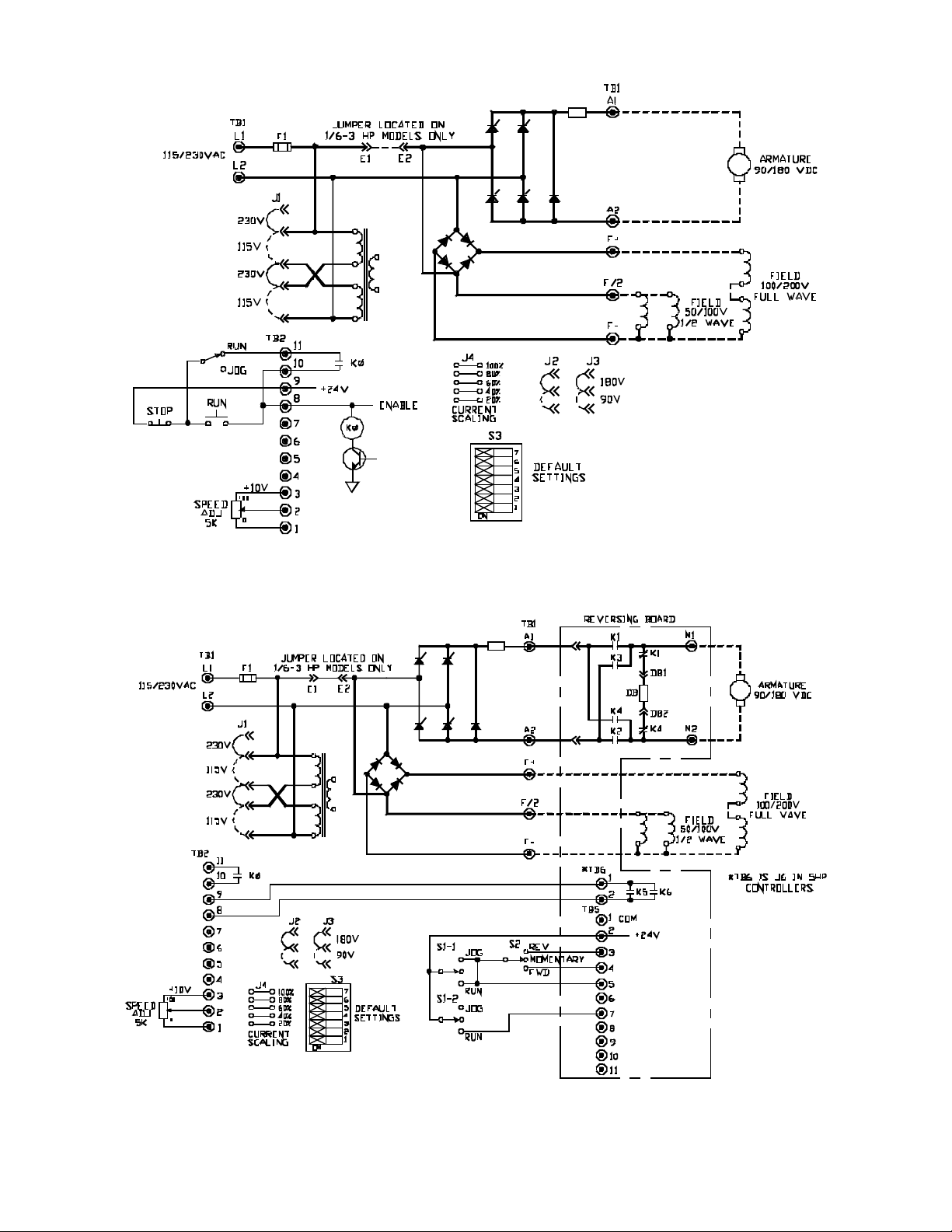
FIGURE 21. S C HE MATIC, SERIES 2600, 5 HP
Page 48

90V/180VDC
JUMPER J3
(Shown in
180VDC Position)
90V/180VDC
JUMPER J2
(Shown in
180VDC Position)
MOTOR CURRENT
JUMPER J4
BOOK0795-F
CONNECTOR J5
ACCELERATION POT
DECELERATION POT
MAXIMUM SPEED POT
CURRENT LIMIT POT
MINIMUM SPEED POT
115V/230VAC
JUMPER J1
(Shown in
230VAC Position)
AC LINE FUSE F1
CONNECTOR E1
CONNECTOR E2
IR/TACH POT
CURRENT LIMIT
INDICATOR
DIP SWITCH S3
LOGIC & SIGNAL
CONNECTION
TERMINALS
AC LINE
CONNECTION
TERMINALS
MOTOR SHUNT FIELD
CONNECTION
TERMINALS
FIGURE 22. SERIES 2600/2610 CONTROL BOARD, 1/6 - 3 HP
43
MOTOR ARMATURE
CONNECTION
TERMINALS
Page 49

BOOK0795-F
90V/180VDC
JUMPER J3
(Shown in
180VDC Position)
90V/180VDC
JUMPER J2
(Shown in
180VDC Position)
MOTOR CURRENT
JUMPER J4
CONNECTOR J6
CONNECTOR J7
ACCELERATION POT
CONNECTOR J5
DECELERATION POT
MAXIMUM SPEED POT
CURRENT LIMIT POT
CURRENT LIMIT
INDICATOR
IR/TACH POT
MINIMUM SPEED POT
DIP SWITCH S3
LOGIC & SIGNAL
CONNECTION
TERMINALS
115V/230VAC
JUMPER J1
(Shown in
230VAC Position)
AC LINE FUSE F1
AC LINE
CONNECTION
TERMINALS
MOTOR SHUNT FIELD
CONNECTION
TERMINALS
MOTOR ARMATURE
CONNECTION
TERMINALS
FIGURE 23. SERIES 2600 CONTROL BOARD, 5 HP
44
Page 50

INDEX BOOK0795-F
A
AC Line Protection 36
AC Supply Transients 4
ACCEL Potentiometer 21
Acceleration 21, 35
Altitude 34
Ambient Temperature 34
Antiplug Circuit 37
Antiplug Feature 18
Anti-restart Feature 38
Armature Feedback 37
Atmosphere 3
Auxiliary Contact 36
B
Branch Circuit Protection 4
C
Calibration 5
Circuit Breaker (Option 1010) 4
Conduit Entry 5
Connector J1 5
Control Voltage 36
Control Wiring 4
Controlled Speed Range 35
Controller Construction 3
Controller Mounting 3
Cover Hinges (Option 1638) 3
CSA 1,4
CUR LMT Potentiometer 23
Current (Torque) Limit Potentiometer 23
Current Limit 23
Current Limiting Fuses 4
Current/Torque Reference Potentiometer 33
D
DC Tachometer Feedback 37
DECEL Potentiometer 21
Deceleration 21, 35
DIP Switch (S3) 37
DIP Switch Settings 36
Displacement Power Factor 35
Duty 33
Dynamic Braking 17
Dynamic Braking Resistors 17
E
Efficiency 35
External DC Signal Follower 38
F
Feedback 37
Field Supply 37
Full-wave Field 6, 7
Fused Disconnect Switch 4
G
Ground Screw 4
Grounding 4
H
Half-wave Shunt Field Voltage 6, 7
Horsepower Range 33
I
IR (Load) Compensation 21, 35
IR/TACH Potentiometer 21, 23
Isolated Regulator 37
Isolation Transformer 4
J
Jog Speed 35
JOG SPEED Potentiometer 18
Jumper J4 5
Jumpers J1, J2, and J3 5
L
Line Frequency Variation 34
Line Fuse 18, 36
Line Fuse Interrupting Capacity 33
Line Power 33
Line Starting 17, 38
Line Supply 4
Line Voltage Variation 34
Low Inductance Motors 6, 7
M
MAX SPD Potentiometer 22
Maximum Speed 35
Maximum Speed (Armature Feedback) 22
Maximum Speed (Tachometer Feedback) 22
MIN SPD Potentiometer 23
45
Page 51

BOOK0795-F INDEX
Minimum Speed 23, 35
Minimum Transformer KVA 4, 33
Motor Contactor 37
Motor Overload 37
Motor Rotation 15
Motor Speed Potentiometer 33
N
National Electrical Code 1, 4
NEMA 1
NEMA Type 4 and 12, 3
O
Offset 23
Options 5
Oscillating Load 26
Overload Capacity, Armature Circuit 33
Overload Circuit 37
Overload Monitor 19
P
Power Bridge 37
Power Conversion 37
Power Factor Correction Capacitors 4
Power Wiring 6, 7
U
Underwriters Laboratories Listed 1
V
Varistor 4, 38
Vibration 3
Voltage Transient Protection 38
W
Wiring Practices 4
R
Relative Humidity 34
S
Selectable Capabilities 37
Service Factor 33
Shielded Wire 5
Shipping Damage 5
Short-circuit Current 4
Signal Wiring 4
Speed Regulation 35
STATUS INDICATOR 38
T
Tachometer Feedback 38
Tachometer Generators 37
Torque (Current) Limit 35
Torque Regulator 38
Transformer 4
Transients 4
46
 Loading...