

Page 1
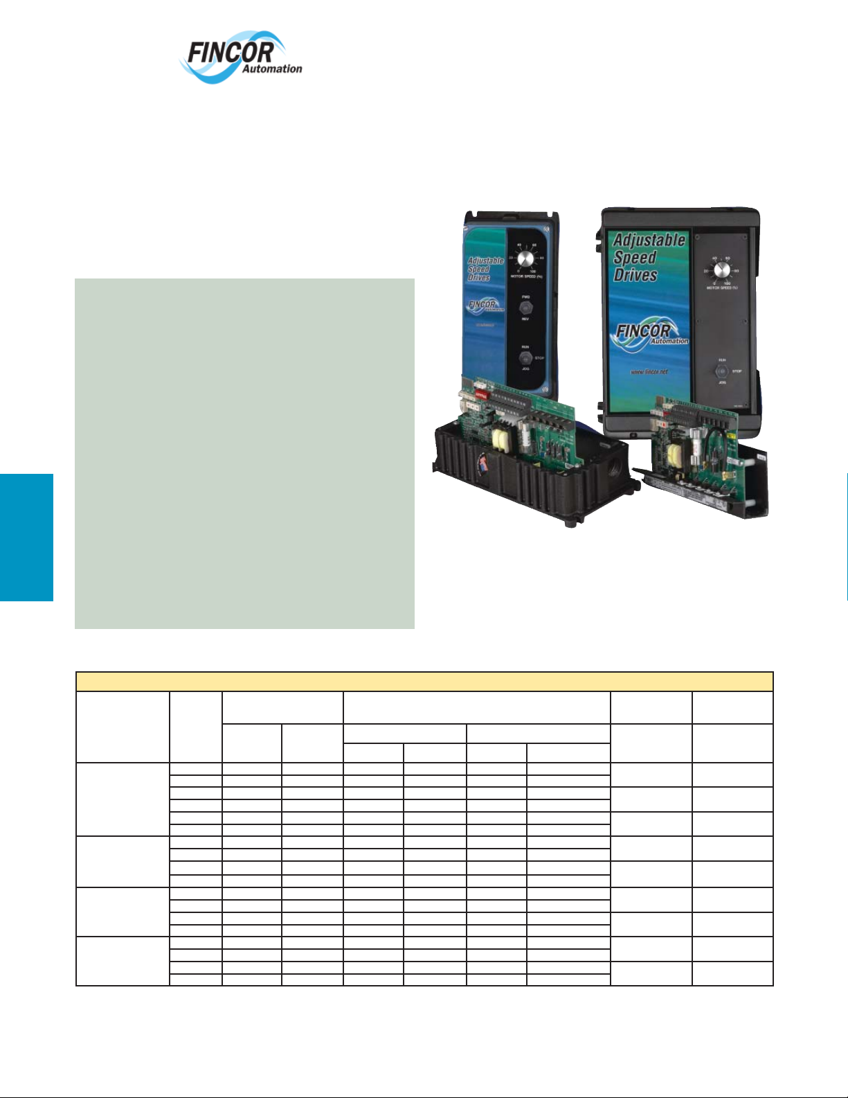
Fincor Series 2230 MKII/2240
Fincor Series 2200 regenerative drives are ideal for your
more demanding applications. They feature flexibility
with ratings up to 5 horsepower. The Series 2230
MKII offers new and improved board design with more
standard features to 3 hp while the larger Series 2240
offers ratings to 5 hp and additional space for internally
mounted options.
FINCOR SERIES 2230 MKII / 2240
•
•
•
•
•
•
•
•
•
•
Speed or Torque Control
0-10 VDC or +/- 10 VDC input signal
Current Stability Adjust
PID / Speed Trim Control
Fused Input
Line Start / Auto Restart Enable / Disable
Dual Field Supply
Tachometer Input standard
Monitoring Output (0-10 VDC or 4-20 mA)
Diagnostic LED
2230 MKII Enclosed
www.emersonct.com
800-334-3040
2240 Enclosed
FINCOR SERIES 2230 MKII SPECIFIC
Fincor 2200
• 1/6 to 3 hp (115-230V)
•
•
(0-10 VDC or 4-20 mA)
•
FINCOR SERIES 2240 SPECIFIC
•
•
RATINGS: 1/6 TO 5 hp (115-230 VAC)
Series 2200 Regenerative DC Drives
Chassis w/o Integral
Operator Controls
Integral Operator
Operator Controls
NEMA 4/12 with
Integral Operator
Units shipped calibrated for desired hp rating but jumpers can be adjusted for others. Units shipped ready for 230VAC but may be reconnected for 115VAC.
Fully Isolated Regulator
Speed or Current Monitoring
Surface mount technology circuit board
1/6 to 5 hp (115-230V)
Motor contactor option mounts inside enclosure
Model Motor
Book Case w/o
Controls
NEMA 4/12 w/o
Controls
HP
1/6 - 1.0 120 15.8 90 50/100 10.5 1.0
1/2 - 2.0 240 15.8 180 100/200 11.6 1.0
1/6 - 1.0 120 15.8 90 50/100 10.5 1.0
1/2 - 3.0 240 22 180 100/200 11.6 1.0
1/6 - 1.0 120 15.8 90 50/100 10.5 1.0
1/2 - 5.0 240 32 180 100/200 25 2.0
1/6 - 1.0 120 15.8 90 50/100 10.5 1.0
1/2 - 2.0 240 15.8 180 100/200 11.6 1.0
1/6 - 1.0 120 15.8 90 50/100 10.5 1.0
1/2 - 3.0 240 22 180 100/200 15.1 1.0
1/6 - 1.0 120 15.8 90 50/100 10.5 1.0
1/2 - 2.0 240 15.8 180 100/200 11.6 1.0
1/6 - 1.0 120 15.8 90 50/100 10.5 1.0
1/2 - 5.0 240 32 180 100/200 25 2.0
1/6 - 1.0 120 15.8 90 50/100 10.5 1.0
1/2 - 2.0 240 15.8 180 100/200 11.6 1.0
1/6 - 1.0 120 15.8 90 50/100 10.5 1.0
1/2 - 5.0 240 32 180 100/200 25 2.0
Input Output Run-Stop,
AC Volts Amps DC Volts Amps Order Code Order Code
Arm
Open Chassis
Field Arm Field
Book Case
Static *
2231 2231B
2232 2232B
2242 2242B
2235 2235B
2236 2236B
2231P0 2231BP0
2242P0 2242BP0
2231P1 2231BP1
2242P1 2242BP1
Run-Stop,
DB **
256
* RUN-STOP, Static, Contactorless Control
** RUN-STOP / DB, Armature Contactor Control & Dynamic Braking
Page 2
www.emersonct.com
)
Adjustable
Speed
Drives
800-334-3040
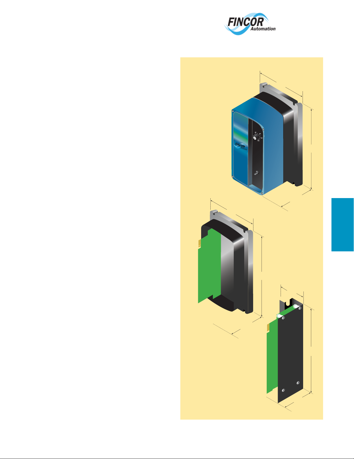
Fincor Series 2230 MKII
DIMENSIONS
SPECIFICATIONS:
Operating Conditions
Horsepower 1/6 thru 3 hp, Jumper Selectable
Line Voltage 115-230VAC ±10%, Jumper Selectable
Enclosure Chassis, Bookcase, NEMA 4/12
Rated Frequency 50/60Hz ±2% Selectable
Ambient Temperature 0 – 40°C (32°F - 104°F) (Enclosed)
0 – 55°C (32°F - 131°F) (Chassis)
Altitude 1000m (3,300 ft)
Relative Humidity 95% Non condensing
Overload Capacity 150% for 1 minute
(UL Listed Motor Overload Protection
– File # E184521)
(120% Timing Threshold)
Standard Features
Isolated Regulator Circuit Grounded I/O signals possible
Regulator Function Speed or Torque selectable
Power Conversion 8 SCR Full Wave - Four Quadrant
Field Supply Full Wave
Protection MOV Voltage Transient Suppression
High Interrupting Capacity Line Fuse
Speed Regulation Armature or DC Tach Feedback
Line Start Selectable for Auto-Restart
Controlled Stop Provides Ramp to Stop Function
Zero Speed Deadband Selectable 2% or Off
Zero Speed Indication Open Collector – Active Low
Direction Indication Open Collector – Active Low = FWD
Speed Regulator Node External PID Input or Speed Trim
Speed Outputs -10 – 10Vdc and 4 – 20ma
Torque Outputs -10 – 10Vdc and 4 – 20ma
Diagnostic LED Green Normal – Red Current Limit
Option Connector Connects Additional Option Boards
Control
Control Logic Power 24VDC for Maintained Switch or
Pushbutton Operation
Speed Potentiometer 5K Ohms, ½ Watt
Input Reference 0 – 10Vdc or -10 – +10Vdc
Speed Regulation 2% with Armature Feedback
(95% Load Change) 0.5% with Tachometer Feedback
Adjustments
Maximum Speed 50% – 100% of Motor Base Speed
Current Limit FWD 0 – 150% of Full Load
Current Limit REV 0 – 150% of Full Load
IR Comp/Tach Scaling 0 – 10% IR or 0 – 100% Tach
Acceleration/Deceleration 0.1 – 30 Seconds
Voltage (Speed) Stability Speed Gain Fine Tune
Current Stability FWD Current Gain FWD Fine Tune
Current Stability REV Current Gain REV Fine Tune
Efficiency
Controller (only) 98%
With Motor (typical) 85%
Approvals & Listings
UL and cUL
2230 MKII
Enclosure
Weight (Chassis)
3 lbs. 1.36 kg
5”
(127 mm)
2230 MKII
Bookcase
Adjustable
Adjustable
Speed
Speed
Drives
Drives
2230
(108 mm)
4.25”
Weight (Enclosed)
3 lbs. 1.36 kg
M
OTO
R SPE
ED (%)
RUN
STO
JOG
P
9.5”
(241 mm)
5”
(127 mm)
2230
5.25”
(133 mm)
2230 MKII
Chassis
Weight (Bookcase)
1 lb. .45 kg
1.75”
(43 mm)
4.25”
(108 mm)
9.5”
(241 mm
8.85”
(218 mm)
Fincor 2200
257
Page 3
www.emersonct.com
800-334-3040
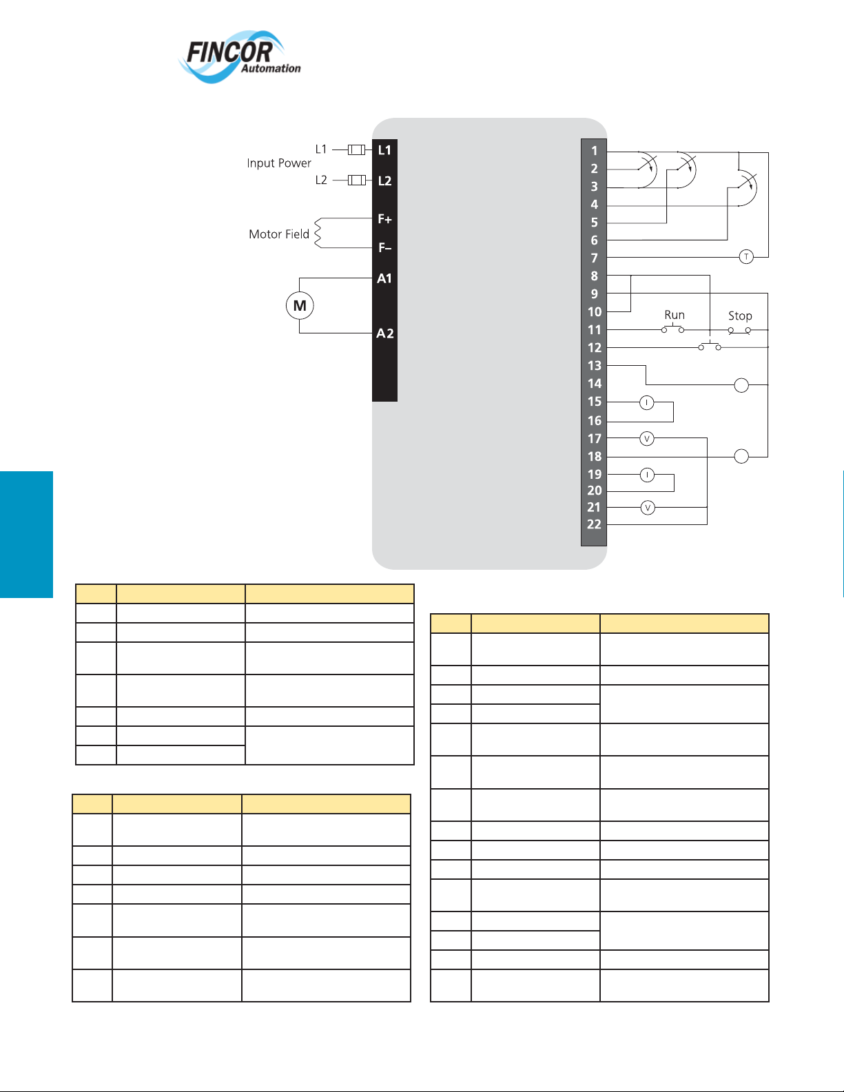
TERMINAL DIAGRAM: 2230 MKII
Fincor 2200
TERMINAL DESCRIPTION
TB1
Circuit Common
Speed Ref Input
Ext Current Ref Input FWD
Ext Current Ref Input REV
Tachometer Fdbk Input
Run Enable Input (+24VDC)
Run Relay N.O. Contacts
Run Relay N.O. Contacts
Controlled Stop Input
Zero Speed Output
Speed Reg Node Input
Cur. (4 to 20mA) Output Speed
Circuit Common
-10 to +10VDC Output Speed
Direction Output
Cur. (4 to 20mA) Output Torque
Circuit Common
-10 to +10VDC Output Torque
Circuit Common
+10V Ref
-10V Ref
+24VDC
TB2
Speed
Ref Pot
Torque
Ref Pot
Torque
Ref Pot
FWD
Controlled Stop
REV
K
K
TB1
Pin# Type Notes
L1 Line Voltage Input 115 or 230VAC J1 Selectable
L2 Line Voltage Input 115 or 230VAC J1 Selectable
F+ Field Voltage Output +100VDC @ 115VAC or +200VDC
F/2 Field Voltage (Half-Wave)
Output
F- Field Voltage Output Field Minus Output
A1 Armature Output -90 to +90VDC @ 115VAC or -180 to
A2 Armature Output
@230VAC Input
+50VDC @ 115VAC or +100VDC
@230VAC Input
+180VDC @ 230VAC Input
TB2
Pin# Type Notes
1 Speed Reference Pot ‘0’ End Speed Pot Common for Uni-Directional
2 Speed Reference Input
3 +10V Reference Output 5ma max
4 -10V Reference Output 5ma max
5 External Current Reference
Input FWD
6 External Current Reference
Input REV
7 Tachometer Input (Speed
Feedback)
Operation
200KΩ Input Resistance
Refer to DIP Switch SW3-2
Refer to DIP Switch SW3-7
3-30VDC, 31-175VDC
TB2 Continued
Pin# Type Notes
8 Enable Input (+24VDC)
– Run Relay
9 +24VDC For drive enable use only
10 Run Relay N.O. Contacts Form A Contact Rated 0.5A @ 115VAC
11 Run Relay N.O. Contacts
12 Controlled Stop Input
(+24VDC)
13 Zero Speed Indication Output Open Collector, Active Low, Rated
14 Speed Regulator Node Input Speed Trim or External PID Input
15 Current Loop Output 4 to 20ma – Speed (Arm Volts)
16 Current Loop Output 4 to 20ma – Speed (Arm Volts)
17 Voltage Output -10 to 10VDC – Speed (Arm Volts)
18 Direction Indicator Output Open Collector, Active Low for FWD;
19 Current Loop Output 4 to 20ma – Torque (Arm
20 Current Loop
21 Voltage Output -10 to 10VDC – Load (Arm Amps)
22 Voltage Output Common Isolated From Line – Can be connected
24VDC @ 6ma Input
or 2A @ 30VDC
Momentary +24VDC Input to Initiate
Controlled (Ramp) to Stop
24VDC @ 50ma
(Bypasses Accel/Decel Ramps)
Rated 24VDC @ 50ma
Amps)
to Earth
258
Page 4
www.emersonct.com
Adjustable
Speed
Drives
800-334-3040
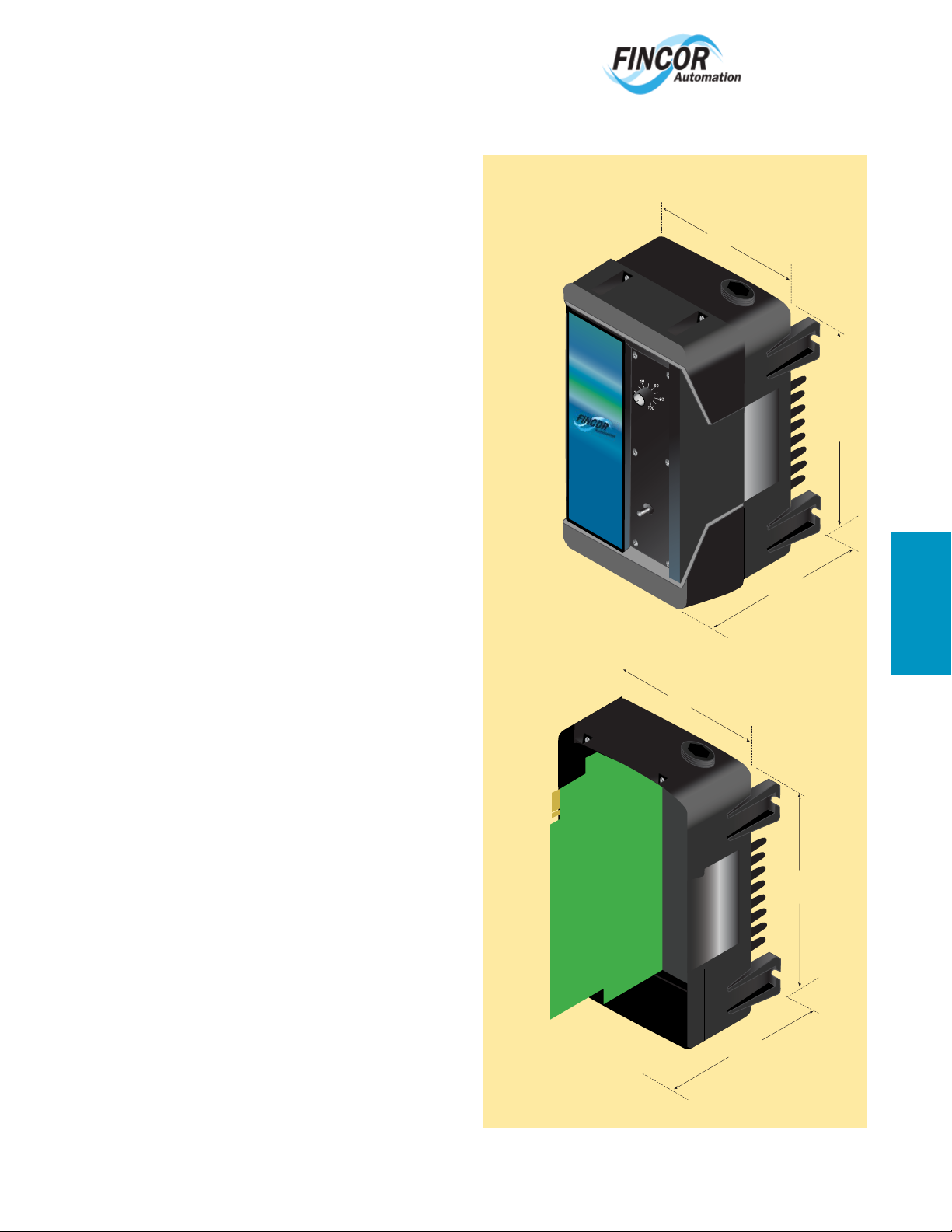
Fincor Series 2240
DIMENSIONS
SPECIFICATIONS:
Operating Conditions
Horsepower 1/6 thru 3 hp, Clip-out Shunt Wires
Line Voltage 115-230VAC ±10%, Jumper Selectable
Rated Frequency 50/60Hz ±2% Selectable
Enclosure Chassis, NEMA 4/12
Ambient Temperature 0 – 40°C (32°F - 104°F) (Enclosed)
0 – 55°C (32°F - 131°F) (Chassis)
Altitude 1000m (3,300 ft)
Relative Humidity 95% Non condensing
Overload Capacity 150% for 1 minute
Standard Features
Regulator Function Speed or Torque selectable
Power Conversion 8 SCR Full Wave - Four Quadrant
Field Supply Full Wave
Protection MOV Voltage Transient Suppression
High Interrupting Capacity Line Fuse
Speed Regulation Armature or DC Tach Feedback
Line Start Selectable for Auto-Restart
Zero Speed Deadband Selectable 2% or Off
Option Connector Connects Additional Option Boards
Control
Control Logic Power 24VDC for Maintained Switch or
Pushbutton Operation
Speed Potentiometer 5K Ohms, ½ Watt
Input Reference 0 – 10Vdc or -10 – +10Vdc
Speed Regulation 2% with Armature Feedback
(95% Load Change) 0.5% with Tachometer Feedback
2240
Enclosure
Adjustable
Adjustable
Speed
Speed
Drives
Drives
Weight (Enclosed)
13.2 lbs. 5.99 kg
M
O
T
O
R
S
P
E
E
D
(%
)
RU
N
STO
JO
P
G
Weight (Enclosed)
13.2 lbs. 5.99 kg
9”
(228 mm)
9”
(228 mm)
8.6”
(218 mm)
12.1”
(307 mm)
Fincor 2200
Adjustments
Maximum Speed 50% – 100% of Motor Base Speed
Current Limit FWD 0 – 150% of Full Load
Current Limit REV 0 – 150% of Full Load
IR Comp/Tach Scaling 0 – 10% IR or 0 – 100% Tach
Acceleration/Deceleration 0.2 – 30 Seconds
Efficiency
Controller (only) 98%
With Motor (typical) 85%
Approvals & Listings
UL and cUL
2240
Chassis
8.6”
(218 mm)
12.1”
(307 mm)
259
Page 5
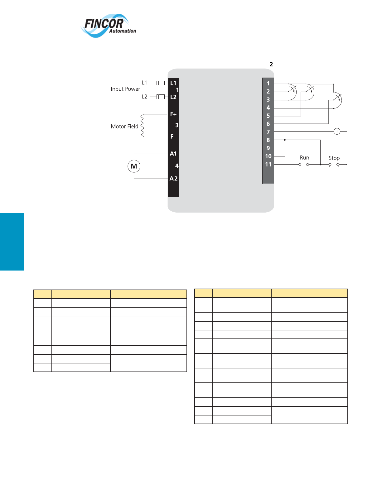
TERMINAL DIAGRAM: 2240
www.emersonct.com
800-334-3040
Fincor 2200
Motor Armature
TB1
TB
TB
TB
Circuit Common
Speed Ref Input
+10V Ref
-10V Ref
Ext Current Ref Input FWD
Ext Current Ref Input REV
Tachometer Fdbk Input
Run Enable Input (+24VDC)
+24VDC
Run Relay N.O. Contacts
Run Relay N.O. Contacts
TB
Speed
Ref Pot
Torque
Ref Pot
FWD
Torque
Ref Pot
REV
TERMINAL DESCRIPTION
TB1
Pin# Type Notes
L1 Line Voltage Input 115 or 230VAC J1 Selectable
L2 Line Voltage Input 115 or 230VAC J1 Selectable
F+ Field Voltage Output +100VDC @ 115VAC or +200VDC
F/2 Field Voltage (Half-Wave)
Output
F- Field Voltage Output Field Minus Output
A1 Armature Output -90 to +90VDC @ 115VAC or -180 to
A2 Armature Output
@230VAC Input
+50VDC @ 115VAC or +100VDC
@230VAC Input
+180VDC @ 230VAC Input
TB2
Pin# Type Notes
1 Speed Reference Pot ‘0’ End Speed Pot Common for Uni-Directional
2 Speed Reference Input
3 +10V Reference Output 5ma max
4 -10V Reference Output 5ma max
5 External Current Reference
Input FWD
6 External Current Reference
Input REV
7 Tachometer Input (Speed
Feedback)
8 Enable Input (+24VDC)
– Run Relay
9 +24VDC For drive enable use only
10 Run Relay N.O. Contacts Form A Contact Rated 0.5A @ 115VAC
11 Run Relay N.O. Contacts
Operation
200KΩ Input Resistance
Refer to DIP Switch SW3-2
Refer to DIP Switch SW3-7
3-30VDC, 31-175VDC
24VDC @ 12ma Input
or 2A @ 30VDC
260
Page 6
www.emersonct.com
800-334-3040
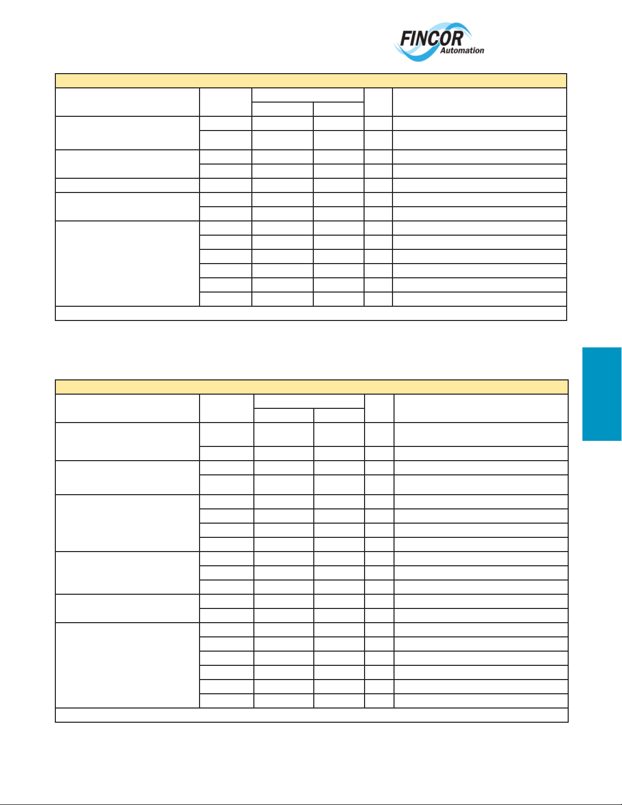
Series 2230 MKII Options with Allowable Combinations
Option Groups Use with
B) Options Used To Convert Open Chassis
Units into Enclosed Package Controllers
— Choice of one within this group.
C) Power Options 2231 - 2236 1001(2 hp) 106242801 XK Armature Contactor With Dynamic Braking (2 hp)
D) Input Signal Options 2231 - 2236 1048 106334702 XK Limit Switch Reversing
E) Feedback Options — Choice of one within
this group.
G) External Options — Choice of any or all
within this group.
Notes: XK–Factory or Field Kit, K–Field Kit, P–Plug-In Option
Model
2231 - 2236 1639 106353803 XK Cover Assembly, Blank Type “P0”
2231 - 2236 1639C 106353801 XK Cover Assembly, Type “P1”
2231 - 2236 1001(3 hp) 106242802 XK Armature Contactor With Dynamic Braking (3 hp)
2231 - 2236 1190 106342803 XK Torque Taper
2231 - 2236 1670 106345202 XK Pulse Tachometer Feedback/Follower
2231 - 2236 1120 104259401 K Operator Control Station — Remote
2231 - 2236 1120A 2660168 K Motor Speed Potentiometer, Ten-Turn With Analog Dial
2231 - 2236 1120B 104192505 K Motor Speed Potentiometer, One-Turn
2231 - 2236 1120C 104319401 K Motor Speed Potentiometer, Ten-Turn With Digital Dial
2231 - 2236 1166 BOOK 0873 K Extra Equipment Manuals
2231 - 2236 1614 106349301 XK Option/Contactor Mounting Kit for 2235 or 2236
Order Code Option
Fact. Install Fld. Install
Option description
Code
Series 2240 Options with Allowable Combinations
Option Groups Use with
A) Enclosure Options — Choice of any or all
within this group.
B) Options Used To Convert Open Chassis
Units into Enclosed Package Controllers
— Choice of one within this group.
D) Input Signal Options — Choice of one
within this group.
E) Feedback Options — Choice of one within
this group.
G) External Options — Choice of any or all
within this group.
Notes: XK–Factory or Field Kit, K–Field Kit, P–Plug-In Option
Model
2242 1170A 106151401 XK Fan Assembly (5 hp Units Only) (Required When En-
2242 1638 105567001 XK Hinge kit to allow the cover to swing open
2242 1639 106356403 XK Cover Assembly, Blank Type P0
2242 1639C 106356401 XK Cover Assembly, Type P1
2242 1001(3 hp) 10624802 XK Armature Contactor With Dynamic Braking (3 hp)
2242 1001(5 hp) 10624803 XK Armature Contactor With Dynamic Braking (5 hp)
2242 1010(3 hp) 105535403 XK Circuit Breaker — Two Pole (3 hp)
2242 1010(5 hp) 105535404 XK Circuit Breaker — Two Pole (5 hp)
2242 1036 106318202 XK Four-Quadrant Acceleration/Deceleration
2242 1048 106334702 XK Limit Switch Reversing
2242 1052 106330702 XK Isolated Input
2242 1190 106342803 XK Torque Taper
2242 1670 106345202 XK Pulse Tachometer Feedback/Follower
2242 1120 104259401 K Operator Control Station — Remote (SCS171)
2242 1120A 2660168 K Motor Speed Potentiometer, Ten-Turn With Analog Dial
2242 1120B 104192505 K Motor Speed Potentiometer, One-Turn
2242 1120C 104319401 K Motor Speed Potentiometer, Ten-Turn With Digital Dial
2242 1166 BOOK 0873-B K Extra Equipment Manuals
2242 1611 106360301 XK Option Guide Card Kit
Order Code Option
Fact. Install Fld. Install
Option description
Code
closed Model 2242 is Operated at 5 hp Rating)
Fincor 2200
261
Page 7

Fincor
www.emersonct.com
800-334-3040
Fincor Series 2330, 2230, 2240, 2600, 2610 Detailed Option Descriptions
Option Controller Description
1001 2230,
1004 2600,
1010 2240,
1015 2600 Magnetic Control Interface for 115VAC control.
1022 2610 Jog, Toggle Switch Selection Option includes a RUN-JOG selector switch and a JOG SPEED potentiometer for installation in the operator control
1036 2240 Four-Quadrant Acceleration/Deceleration — This option board has four adjustment potentiometers consisting of a forward acceleration potenti-
1037 2600 Input / Feedback Adapter Interface Board - Brings the internal regulator circuits of the control board to screw terminal connection points.
1037A 2600 Input / Feedback Adapter, 1-Position - Assembly capable of accepting either a standard input option board or a feedback option board. (external)
1037B 2600 Input / Feedback Adapter, 2-Position - Assembly capable of accepting feedback and input boards. (external)
1048 2230,
1049
1050
1050A
1052 2240 Isolated Input and Follower — This option board isolates the motor speed potentiometer from the non-isolated controller for operator and equip-
1055 12600,
1057A
1058A 2610 Manual/Follower Mode Select (Toggle Switch) This option is intended as a companion to Option 1055, Option 1049 and Option 1052. Options
1059
1059A 2610 This option provides a ±24/12VDC power supply source to provide power to operate a remote transmitter requiring an external power source. It
1061C 12600 AC or DC Tachometer Feedback
1062A 2600,
2240
2610
2600
2240
1
2600 External DC Signal Follower Provides necessary impedance matching, isolation, signal conversion and fi ltering as required to adjust the speed of
1
2600,
2610
1
2600,
2610
2610
1
2600,
2610
1
2600 Precision Reference - Includes a regulated power supply.
2610
Motor Contactor with Dynamic Braking — The basic series 2230 and 2240 controllers are designed for bidirectional operation without an
armature contactor. This option provides a two pole armature contactor which is necessary whenever the application requires a positive disconnection of the rectifi ed armature source from the motor on a stop command. This option also includes a dynamic braking resistor which provides
exponential rate braking of the DC motor armature and an anti-plug circuit to prevent restarting the controller until the braking cycle is complete.
The dynamic braking resistor is rated for stopping a typical load, when the external machine inertia does not exceed that of the motor armature.
Armature Contactor Kit - Reverse Run and Dynamic Braking. This option is included with reversing and DB confi gurations.
AC Line Circuit Breaker, Two Pole — Provides a two-pole, magnetic only, fast trip circuit breaker as a means of manually disconnecting the Model
2242 controller from the AC line. The high interrupting capacity fuse in the basic unit is retained as primary short circuit protection.
panel. The RUN-JOG toggle switch (maintained) contacts in the operator station open the contactor seal-in circuit. Controller then jogs when the
RUN pushbutton is pressed and held at the JOG SPEED potentiometer setting. Jog action is momentary, causing motor rotation only when the
RUN pushbutton is depressed. This option is also suitable for reversing units where identical forward and reverse jog speeds are acceptable.
ometer, a forward deceleration potentiometer, a reverse acceleration potentiometer and a reverse deceleration potentiometer. The potentiometers
have an adjustment range of .3 to 30 seconds.
Limit Switch Reversing — This option board allows interfacing the controller with a variety of external devices, such as limit switches, push
buttons and potentiometers. There are two speed potentiometers on this board, one for forward speed and one for reverse speed. These internal
potentiometers can be switched out if external potentiometers are required. In addition, this board will allow a controlled stop feature with an
adjustable speed dropout.
the drive (or drives) from an external DC signal source.
External AC Signal Follower Provides necessary impedance matching, isolation, signal conversion and fi ltering as required to adjust the speed of
the drive (or drives) from an external AC signal source.
AC Current Transducer Follower, Intended for automatic control systems where it is necessary for the drive to follow an AC signal proportional to
the load current of an AC constant speed, induction motor. Typical examples are conveying systems where the material feed rate has a direct infl uence over the loading of the AC motor, i.e: the carriage or conveyor feeding logs to a saw powered by an AC motor. In order that a proper current
transformer may be supplied it is necessary that nameplate data such as horsepower, voltage, load current, etc. be provided from the AC motor.
ment safety. Also, it will allow the controller to follow a 4-20mA DC current signal and a wide range of DC voltage signals (±.05 to ±500 VDC).
This makes the option ideal for following signal transducers, motor shunts, DC tachometer generators and the armature voltage from DC motors.
AC or DC Tachometer Generator Follower, Intended for automatic control systems where it is necessary for the drive to follow the speed of a preceding drive unit or rotating machine coupled to an AC or DC tachometer generator. The tachometer voltage signal provides the speed reference
for the “follower” drive. Option 1055 is not recommended for use where multiple drive controllers are required to operate from a common signal
source, unless the controllers are isolated.
Digital Pulse Generator Follower, This option provides signal conditioning and isolation for accepting a signal from a magnetic pulse pick-up
mechanically coupled to a preceding drive motor, rotating machinery or various static pulse generators permitting the drive to follow at an adjustable ratio.
1055, 1049 and 1052 do not include a selector switch and rely upon a zero speed setting of the MOTOR SPEED potentiometer to transfer to
full automatic control by the external signal. Option 1058A, when used with these options, allows manual switch selection of either the MOTOR
SPEED potentiometer or automatic control by the external signal. Option 1058A includes a switch with a MANUAL/FOLLOWER legend plate for
installation in the operator control panel.
has a power output capability of 100mA total for all the power outputs inclusively. This option requires external mounting by the customer and
requires a .5amp fused 115/230V power source supplied by the customer.
Digital Pulse Generator Feedback, Provides signal conditioning and isolation for accepting a signal from a magnetic pulse pick-up mechanically
coupled to the drive motor armature. The magnetic pulse pick-up must provide a minimum of 450 pulses per second at motor speed (60 tooth
gear on a 1750 RPM motor). The pulse pick-up signal defeats the IR compensation circuitry in the drive controller, making the unit directly sensitive to motor speed. Speed range is limited to 35:1. The option results in improved speed regulation with load changes (equal to DC tachometer
feedback) and reduced sensitivity to operating conditions such as line voltage variations, ambient temperature changes, motor fi eld heating and
other variables.
262
Page 8

www.emersonct.com
800-334-3040
Fincor Series 2330, 2230, 2240, 2600, 2610 Detailed Option Descriptions
Option Controller Description
1064A 2610 Current Regulator Follower, Provides a means of controlling motor armature current and torque by a manually adjusted potentiometer or an
1072 2600A Auxiliary Contacts - This option can only be used with the 2601A and 2602A if it is to be mounted in the controller enclosure.
1081B 22600,
2610
1120A 2330,
2240,
2600,
2610
1120B 2330,
2240,
2600,
2610
1120C 2330,
2240,
2600,
2610
1170A 2240,
2600
1072 2600A Auxiliary Contacts - This option can only be used with the 2601A and 2602A if it is to be mounted in the controller enclosure.
1081B 22600,
2610
1190 12230,
2240,
2600,
2610
1220 12600,
2610
1611 2240 Option Card Guide Kit — This option is required when mounting the option cards in the 2242 enclosure or if the option cards are mounted
1614 2230 Option Mounting Kit — This kit contains standoffs for mounting an optional contactor or option board onto a Series 2235 or 2236 “Bookcase”
1638 2240,
2600
1639 2230,
2240
1639C 2230,
2240
1670 2230,
2240
1775 2600,
2610
Notes:
1 Requires Option 1775 Signal Options Interface.
2 Not compatible with tachometer feedback.
external DC voltage reference signal. The circuit includes internal isolation permitting direct connection to a grounded signal source or the armature circuit shunt of another DC drive controller. Since torque is directly controlled independent of motor speed, provision is included for limiting
maximum motor speed.
Torque (Current) Monitor Provides an adjustable, static circuit that monitors motor armature current and provides a programmed shutdown of
the drive under sustained overload conditions to prevent motor damage. The circuit provides greater versatility than the standard, nonadjustable
overload circuit calibrated to trip whenever armature current exceeds 120% for 80 seconds.
Potentiometer, Ten-Turn Motor Speed (Analog Dial) — Provides a ten-turn, 2W potentiometer, knob and analog counting dial for separate mounting by user.
Potentiometer, Single-Turn Motor Speed Assembly — Provides a single-turn, 2W potentiometer, knob and dial wired to a terminal board for
separate mounting by user.
Potentiometer, Ten-Turn Motor Speed (Digital Dial) — Provides a ten-turn, 2W potentiometer, with digital counting indicator dial assembly for
separate mounting by user.
Fan Assembly — All 2242 enclosed models (used for 5 hp) require this fan assembly when operated at the fi ve horsepower rating in a 40°C environment. Option includes a special base assembly/air baffl e with a 24 VDC fan powered by a power supply within the Model 2242. This option
may also be used for ratings less than fi ve horsepower when open chassis models must operate in environments greater than 55°C, and enclosed
models above 40°C.
Torque (Current) Monitor Provides an adjustable, static circuit that monitors motor armature current and provides a programmed shutdown of
the drive under sustained overload conditions to prevent motor damage. The circuit provides greater versatility than the standard, nonadjustable
overload circuit calibrated to trip whenever armature current exceeds 120% for 80 seconds.
Torque Taper— This option consists of a plug-in circuit board. This board provides an inverse-linear speed-torque relationship when operating in
the braking (regenerative) mode, and provides constant torque in the motoring mode of operation. Motoring torque and braking torque are individually adjustable as well as forward and reverse torque taper. Applications include the following: 1. Winders where the material being wound
travels at a constant speed during winder roll buildup. 2. Unwinders, since this option provides relatively constant holdback tension (±20%) from
full roll to empty roll.
Constant Velocity Winder This option provides an economical but accurate method of automatically controlling the tension of process material in
strip, web, wire or cable form as wound by a center driven winder.
external.
chassis.
Hinge Kit, Enclosure Cover — Model 2242 enclosed controllers include a screw fi xed, gasket cover which is removable for increased accessibility
during installation, troubleshooting or repair. When desired the cover may also be provided with optional hinges making servicing more convenient. This option may be provided factory installed or a kit is offered for simple fi eld installation.
Cover Kit, Blank Type “P0” — Provides an enclosed blank (no operator devices) cover for fi eld conversion of open chassis models (except 2235,
2235B, 2236 and 2236B models) into an enclosed unit for remote control.
Cover Kit, Type “P1” (Run-Stop-Jog) — Provides an enclosed (run-stop-jog switch with motor speed potentiometer) cover for fi eld conversion of
open chassis models (except 2235, 2235B, 2236 and 2236B models) into an enclosed unit for local control.
Pulse Tachometer Feedback/Follower — This option interfaces the controller to a pulse train for speed reference or as a feedback signal. It
allows the use of a 60 tooth gear for either speed reference or feedback. It is capable of providing digital pulse tach reference and/or feedback
functions. The sensor can be a magnetic pickup (2 wire), proximity sensor (3 wire), AC tachometer generator (18 cycles/revolution), two-phase AC
tachometer generator, or digital tachometer generator or encoder (240 pulses/revolution). Note: two phase AC tachometer generator can be used
for follower or feedback applications, but not both.
Signal Options Interface. Required to enable the use of all options marked with Note (1). Option 1775 mounts within the chassis of Models
2601 or 2602 and externally when used with Models 2611 and 2612.
Fincor
263
 Loading...