

Fimco MS-25BU Owner's Manual
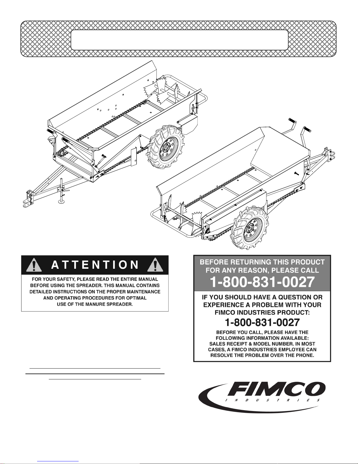
OWNER’S MANUAL
Model: MS-25BU
(5301194)
(25 Bushel Pull-Behind
Manure Spreader)
General Information
Thank you for purchasing this product. The purpose of this
manual is to assist you in operating and maintaining your
manure spreader. Please read it carefully, as it furnishes
information which will help you achieve years of trouble-free
operation.
Warranty
Products are warranted for one year from date of purchase
against manufacturer or workmanship defects for home owner
usage and 90 days for commercial usage.
For technical assistance, visit our website @
www.fimcoindustries.com or call: TOLL FREE @ 1-800-831-0027
Our Technical Support Representatives will be happy to help you.
To obtain prompt, efficient service, always remember to give the
following information…
Correct Part Description and/or part number
Model #/Serial # of your sprayer
Part descriptions and numbers can be obtained from the illustrated
parts list section(s) of this manual.
www.fimcoindustries.com
1000 FIMCO Lane, P.O. Box 1700, North Sioux City, SD 57049
Toll Free Phone: 800-831-0027 : Toll Free Fax: 800-494-0440
[5004582 (02/17)]
Page 1

Assembly Instructions
1. Remove all parts of the manure spreader from the crate.
A. Note that the tongue is fastened to the crate. Free the
tongue parts from the crate and then remove the top
cross boards.
B. The wheels and tires may be lifted from the unit frame.
C. Note the small parts bag with the wheels, open it and
remove the contents.
2. Attach the tongue to the main frame using (4) 5/16-18nc x 1”
carriage bolts and (4) 5/16” lock nuts. You may want to refer to
the exploded view drawings.
3. The control levers must be attached to the bolt on each side,
near the front of the frame. The lock nuts are already attached
to the appropriate parts. Remove them, affix the parts in place
and secure the parts with the lock nuts. Use a 5/16” lock nut to
hold the control levers in place. Tighten the lock nut so that the
levers may pivot easily, but with a minimum of play. You can
now join the gas shock (Item 23) to the lever on the left front
end using a 5/16” lock nut.
4. Place the manure spreader onto a platform at 12” from the
ground. Use a front end loader or a jack to raise the spreader
safely.
A. Note there are right and left wheels. The tread should
point to the rear as viewed from top of the tire.
B. Each wheel is to be attached using (4) bolts (Item 39)
and (4) wheel nuts (Item 38).
Parts Included in Crate
1. Main Frame Assembly
2. Tongue & Hitch Assembly
3. (2) Wheels & Tires
4. Small Parts Bag
A. (8) 1/2”-20 Hex Cone Wheel Nuts
B. (4) 5/16” Whiz Nuts
C. (4) 5/16”-18-1” Carriage Bolts
D. (8) 1/2”-20 x 1-1/8” Serrated (Knurled) Shoulder Bolts
E. (1) Hitch Pin Clip
F. (1) Parking Stand Weldment
G. (1) Gas Cylinder 40 psi Shock
Operating Instructions
1. The towing vehicle should be at least of a 10 H.P. variety.
2. The spreader has an adjustable hitch. Set the hitch so the
adjustable hitch range is from 7” - 16”.
3. Be sire the towing vehicle can not move when attempting to
hitch up to the spreader.
4. Use a quality hitch pin equipped to prevent accidental
unhitching.
5. Be sure the safety guards are in place.
6. The control levers should be in the “off” position (rotated down-
wards) until you are ready to spread manure. Be sure to stop
before engaging the controls.
7. Begin loading to the front end of the spreader and gradually
work to the rear end.
8. Do not load above the side or front panels.
9. Always allow clearance for the rotary blad mechanism to turn
freely before engaging the chain mechanism.
10. It is important to free up any manure that may be frozen or ad-
hered to the floor. This will prolong the life of the drive chain. It
is also a good idea to know that the detachable chain mechanism (slide bar) is not adhered to the floor board. This can happin cold weather when moisture freezes to the chain and floor.
11. Stop moving before engaging or disengaging the controls to the
chain drive mechanisms.
12. The proper speed for the desired spreading is from 3-1/2—5
MPH. Do not exceed 5 MPH or excessive wear and tear will
occur.
13. Always disengage both controls before backing up. Reversing
the chain drive mechanism will cause damage to the drive
mechanism.
14. It is a good idea to use a slow moving vehicle sign for road
travel.
15. Use safe practices when operating the spreader. Better to be
safe than sorry.
16. Cleaning the spreader after each use will prolong the life of the
spreader and make maintenance easier.
17. Be sure to oil the roller chain, as well as the detachable chain,
and grease the axle and the pivoting shaft bushings for the
rotary blades. A regular practice of maintenance will prolong the
life of the spreader.
18. Raise the control levers to engage the ground drive mecha-
nisms.
General Maintenance
Do not attempt, under any circumstance, to work with the chain
drive mechanisms while the spreader is moving. To clean, ser-
vice, adjust, unclog or any other function, the spreader must be stationary. (Even though it would appear to be safe). If the mechanism
starts to move, your safety could be at risk. Follow these steps before
attempting to maintain or repair any part of the spreader.
1. Unhitch the spreader from the towing vehicle.
2. Block both wheels front and back or raise the entire spreader.
Support the spreader so the wheels may turn if necessary. Use
care to provide adequate stationary support.
3. Engage the control levers only to move the drive chain mecha-
nism.
4. Always be sure the safety guards are in place after maintenance
and before moving the spreader.
5. Oil the roller chain and detachable chain once a week or as use
and weather conditions demand. Do not let the chains go dry.
6. Grease the bushings for the axle shafts, the shafts for the rota-
ry, blades and the shaft for the detachable chain drive.
7. Cleaning the spreader after each use will prolong its life and
make the maintenance easier.
Floor Chain Drive Mechanism Adjustment
Periodically adjustments must be made to your manure spreader in
order to keep it in peak operating condition. One area which may
require periodic adjustment (to compensate for normal usage wear)
is the floor chain drive mechanism.
Page 2
Assembly Instructions
Step 1: On a flat and level surface, unhitch the spreader from its
towing vehicle.
Step 2: Adjust front tip stand so unit is in a reasonably level position.
Step 3: Inspect cam follower roller (Item 32), shown in Detail C, and
replace if worn.
Step 4: Raise handle (Item 16), shown in Detail B, on floor chain
drive mechanism side only, to its full upright (engaged) position.
Step 5: Roll spreader slightly, a few inches should do the trick, either
forward or rearward until the cam follower roller resides at its lowest
point on cam (Item 34), shown in Detail C. See Figure 1.
4.28
Step 6: At this point block both wheels, front and back, to secure the
spreader in place.
Step 7: Using a needle nose pliers, unseat the lower end of the 6”
spring (Item 46), shown in Detail C, from its vertical mounting bracket.
Step 8: Remove left side shield (Item 48), shown in Detail D. Set
shield and hardware off to the side for the time being.
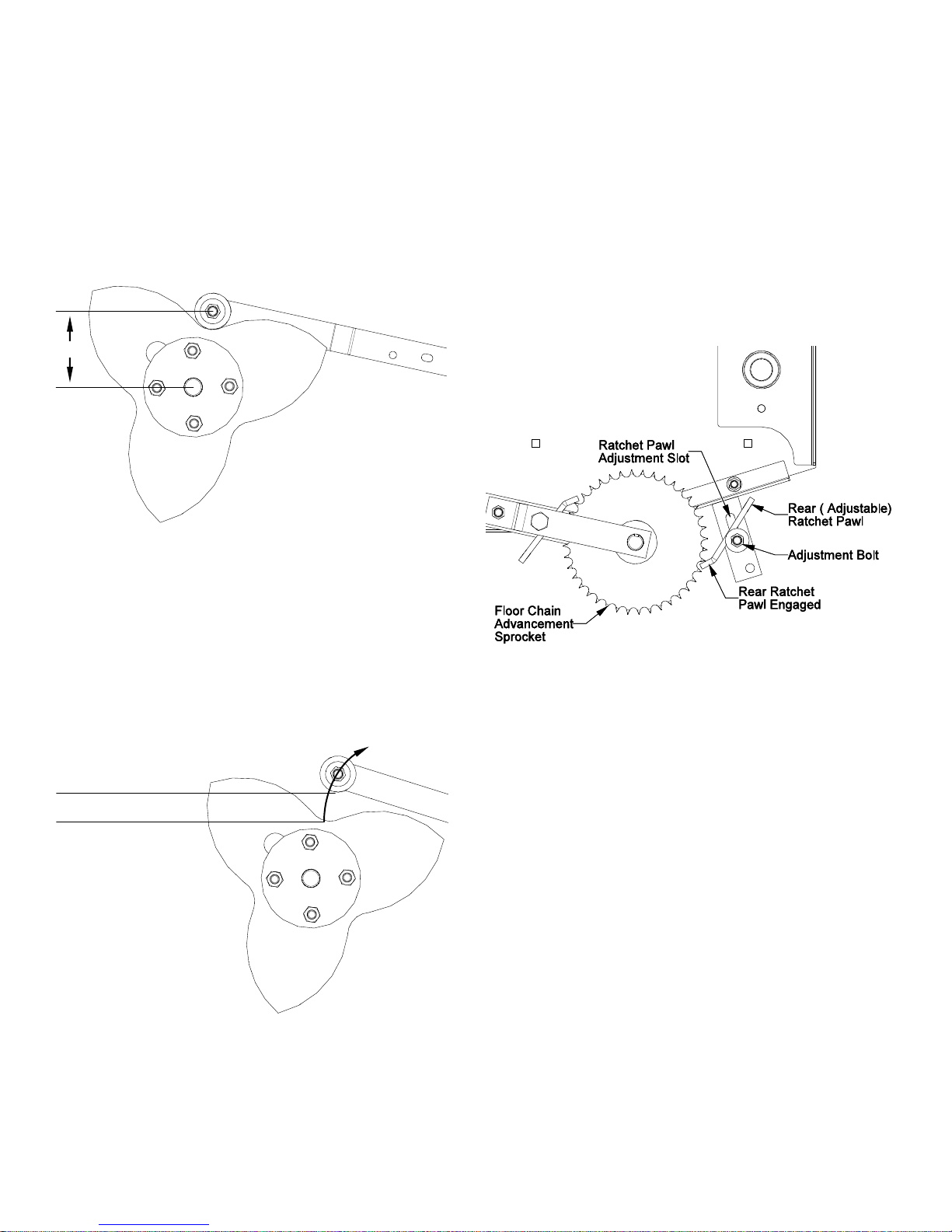
Step 9: Next, slowly lift the cam follower roller (Item 32) upward until
the rear ratchet pawl engages. The instant the rear ratchet pawl becomes engaged, a reasonably loud “click” should be heard. Refer to
Figure 2.
Rear Rachet Pawl should
become engaged at between
3” to 4” of elevation
3½” = Optimal Setting
in most instances
**NOTE** It is crucial that the lifting of the cam follower roller is
stopped the very instant the rear ratchet pawl becomes engaged, in
order to provide an accurate reading for set-up. If you happen to go
too far, simply push the cam follower roller back down into its lowest
position and lift again slowly.
The optimal setting most instances is 3½”, depending upon the
spreader’s age and wear pattern.
Figure 1
Figure 2
Step 10: If the rear ratchet engages too quickly or does not engage
soon enough, it is out of phase and must be repositioned.
Step 11: Repositioning of the rear ratchet pawl is accomplished quite
simply by loosening the rear ratchet pawl adjustment bolt and moving
it either up or down with the ratchet pawl adjustment slot and then
retightening. Refer to Figure 3.
Some trial and error may be involved in this process, as every
spreader will require slightly different settings to achieve proper lift
distance of the cam follower.
Step 12: Re-attach the 6” spring to its vertical mounting bracket, as
well as the left side shield, prior to testing.
Step 13: Test empty spreader at a reduced speed for a period of time
insuring the floor chain drive mechanism is running smoothly.
Step 14: Place back in service.
Figure 3
Page 3

MS-25BU
(5301194)
See Detail A
See Detail I
See Details C
See Detail B
See Detail E
See Details J for Underside of Spreader
**Refer to all detail views for parts call-out
and notes on following pages**
See Detail D
See Detail F
See Detail H
See Details G
Page 4
 Loading...