

Fimco LG-60-3PT-WP-309-BL-TSC Owner's Manual
OWNER’S MANUAL
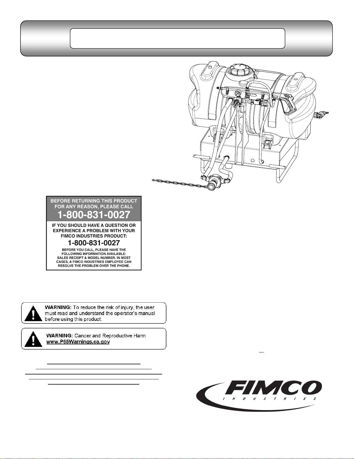
Model:
LG-60-3PT-WP-309-BL-TSC
(2152251)
(60 Gallon 3 Point Sprayer w/Pump, Coupler &
3-Nozzle ‘Boomless’ Boom Assembly)
Information About the Sprayer
Roller pumps are positive displacement pumps, which means that the
entire solution being pumped must go somewhere or the pump will
break. In this roller pumping system, solution is drawn from the tank
and forced to a planned source, such as boom nozzles or handgun.
The pressure is controlled by a pressure relief valve, which is a spring
-loaded device that controls the amount of fluid bypassed
(recirculated) to the tank. The gray adjusting cap is to be tightened to
increase pressure and loosened to decrease pressure.
The ‘directo-valve’ is the on/off control which allows the operator to
manually control the solution going to the boom.
Category I
Caution: When fully filled with water,
this sprayer will weigh approx. 700
lbs.. Consult the owner’s manual for
your vehicle to verify that you are
within it’s load carrying capacity.
General Information
Thank you for purchasing this product. The purpose of this
manual is to assist you in operating and maintaining your
3-Point sprayer.
Retain a copy of your receipt for your unit,
as it will be required to validate any warranty service
Products are warranted against manufacturer or workmanship
defects for one year from date of purchase for home owner
usage and 90 days for commercial usage.
For technical assistance, visit our website @
www.fimcoindustries.com or call: TOLL FREE @ 1-800-831-0027
Our Technical Support Representatives will be happy to help you.
To obtain prompt, efficient service, always remember to give the
following information…
Correct Part Description and/or part number
Model #/Serial # of your sprayer
Part descriptions and numbers can be obtained from the illustrated
parts list section(s) of this manual.
Assembly Instructions
Most of the sprayer has been assembled at the factory.
Center the boom tube on the boom mounts and secure in
place with the (2) round U-bolts and whiz nuts provided.
Make sure the U-bolts are positioned within the grooves of
the grommets on the boom tube. Refer to page 2 to attach
the end nozzles to the boom.
NOTE: The purpose of these grommets is to prevent metal-to-metal contact between the U-bolts, boom tube and
boom mounting brackets.
The grommets will ‘compress’ as you tighten the whiz locknuts onto the U-bolts. Tighten just so that the boom tube will
NOT rotate within the grommets. Alternate the tightening of
the locknuts to provide even pressure on the grommet.
**DO NOT OVER TIGHTEN the whiz locknuts, as this may
cause the boom tube to flatten slightly!
Attach the boom feeder hose to the boom after routing it
through the underside of the carrier frame as needed. Secure
in place with a hose clamp provided.
Poly hose fittings (5010209) are included to be joined to the
pump. A torque chain, ‘S’-Hook and hardware are also included for the pump. The pump IS included with this unit. It is
intended for a pump to be mounted directly to the tractor
PTO.
www.fimcoindustries.com
1000 FIMCO Lane, P.O. Box 1700, North Sioux City, SD 57049
Toll Free Phone: 800-831-0027 : Toll Free Fax: 800-494-0440
[5008057 (11/18)]
Page 1
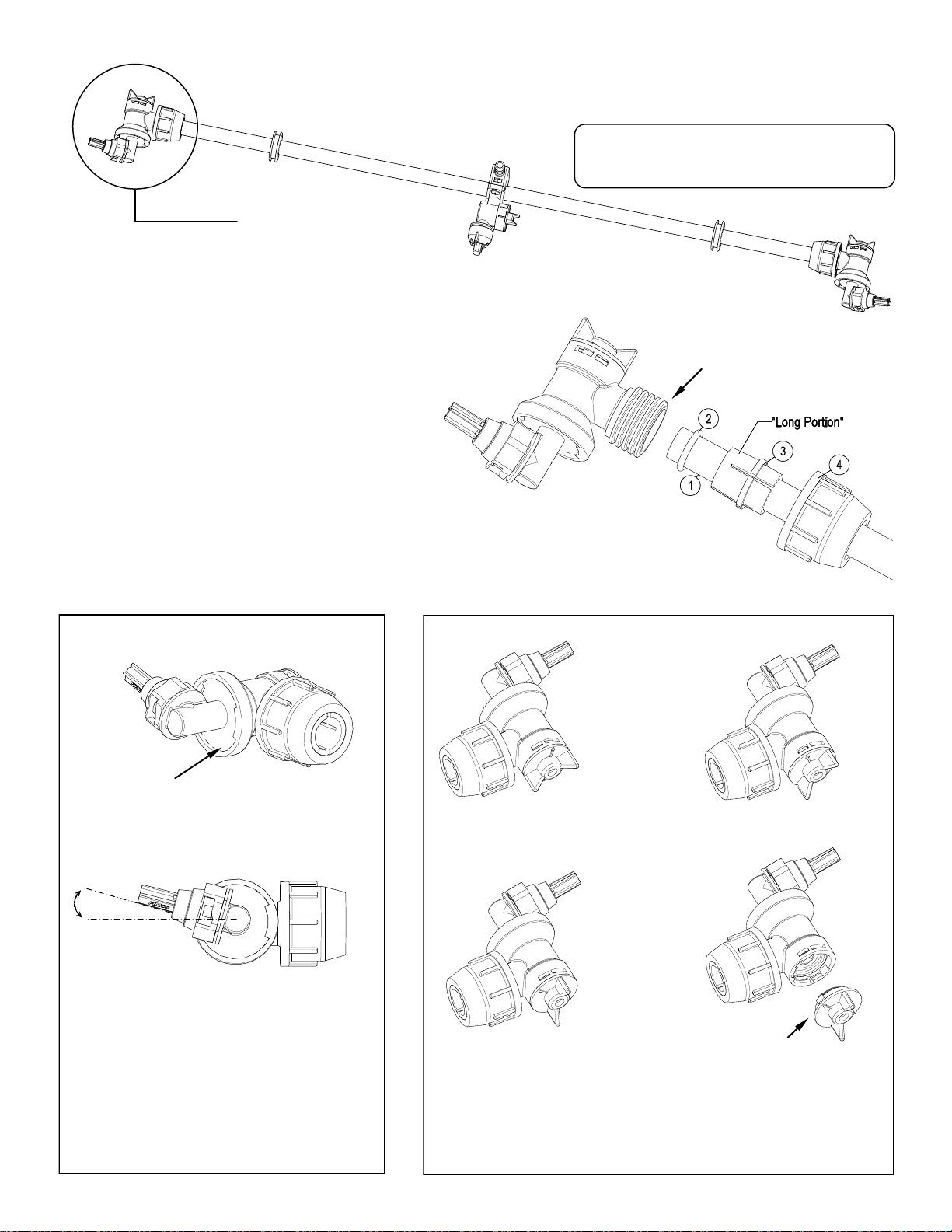
End Nozzle Assembly Procedure
For Boomless “Wet” Boom
Assembled
End Nozzle
1. Start by sliding Item 4, 3, 2 onto the boom tube
(Item 1) as shown, leaving about 1/2” to 3/4”
between the end of the boom tube and Item 2,
and make sure the “Long” portion of Item 3 is facing the nozzle end.
2. Slide the (complete) end nozzle assembly onto the
stainless steel boom tube, with a somewhat
“twisting” motion, so that the end face of the boom
tube “butts” up against the surface face inside the
nozzle body.
3. Now push the “compression olive” (Item 3) against
O-ring (Item 2) and slide (both) into the nozzle
body opening firmly.
4. Firmly tighten flynut (Item 4) onto threads of
nozzle body.
5. Repeat for other side.
NOTE: If water is shooting back on the boom tube,
item 2 is not in the correct placement.
Your boom will come with the (2) end nozzle assemblies
NOT affixed to your boom tube. Follow the instructions
below to attach these properly to the boom tube, as
shown.
Item 2 is shipped inside of
the end nozzle assembly.
Remove & place on tube.
End Nozzle Informaon
(5275122)
This nozzle mounng stem
Has a ratcheng moon.
** Each “click” of the ratcheng moon is approx. 15° **
15°
For proper/opmal spray coverage,
The nozzle must be at a 15° angle
The 15° angle shown will prevent the outer
Nozzles from overlapping with the center nozzle.
“On/O” Valve Posions
Valve “Open” Valve “Closed”
Service Posion On/O Valve Knob
Eliminate line pressure, then pull out
to check diaphragm condion.
Page 2
Note: The check valve & diaphragm can fall out during transport, if the
knob is not turned to the “ON” or “OFF” posion.

Pressure
(p.s.i.)
Capacity
(g.p.m.)
(3 nozzles)
1
MPH2 MPH3 MPH4 MPH5 MPH6 MPH8 MPH
20
30
40
1.68
2.05
2.40
28.0
34.4
39.6
14.0
17.2
19.8
9.4
11.4
13.2
7.0
8.6
9.9
5.6
6.9
7.9
4.7
5.7
6.6
3.5
4.3
5.0
Pressure
(p.s.i.)
Capacity
(g.p.m.)
(3 nozzles)
1
MPH2 MPH3 MPH4 MPH5 MPH6 MPH8 MPH
20
30
40
1.68
2.05
2.40
0.64
0.78
0.90
0.32
0.39
0.45
0.21
0.26
0.30
0.16
0.20
0.23
0.13
0.16
0.18
0.11
0.13
0.15
0.08
0.10
0.12
Pressure
(p.s.i.)
Capacity
(g.p.m.)
(3 nozzles)
1
MPH2 MPH3 MPH4 MPH5 MPH6 MPH8 MPH
20
30
40
1.68
2.05
2.40
0.064
0.078
0.090
0.032
0.039
0.045
0.021
0.026
0.030
0.016
0.020
0.023
0.013
0.016
0.018
0.011
0.013
0.015
0.008
0.010
0.012
Gallons per Acre Based on Water - 17 1/2" Spacing
Note: The same figures are used for 1, 2, or 3 nozzles.
Gallons per 1000 Sq. Ft. based on Water - 17 1/2" Spacing
Gallons per 100 Sq. Ft. based on Water - 17 1/2" Spacing
Attach the sprayer to the tractor 3 point hitch. Mount the pump to the
Testing the Sprayer
PTO and affix the torque chain. Open the tank lid and be sure the
tank is clean and free of foreign material.
NOTE:
It is VERY important for to test your sprayer with plain water before
actual spraying is attempted. This will enable you to check for leaks
without the possibility of losing any expensive chemicals.
Fill the tank about 1/2 full with plain water.
Before starting, open the suction line valve (located underneath the
carrier frame), turn the relief valve handle out to lower the line
pressure. This will help prime the pump.
CAUTION:
Always be sure that the water (or solution) has reached the pump
before starting your sprayer. If the pump is allowed to run dry,
serious damage to the pump will result.
Always have the pressure line open to the tips so that the air which
may be trapped in the line will be forced (or purged) out.
Start the tractor PTO. Check the entire system for leaks. Once the
pump is primed, the pressure may be increased by turning the
handle of the pressure relief valve in. Keep the pressure line open to
the tips when setting the pressure. Set the pressure and then lock
the relief valve handle in place. Shut off the directo-valve and check
for leaks again. Pressure will increase when the pressure line valve
is closed and then return to the preset pressure when the valve is
opened again.
During the testing period, be sure to observe the spray pattern given
by the spray nozzles. If there is any pattern distortion, it will be
necessary to remove and clean the affected tips.
Caution:
Never use a metal object or other sharp item for cleaning a nozzle
tip. It is better to use a nozzle brush (NOT wire brush) or compressed
air for tip cleaning.
Conditions of weather and terrain must be considered when setting
the sprayer. Do not spray on windy days. Protective clothing must be
worn in some cases
Be sure to read the chemical label(s) before application!
Operation & Calibration
The performance of any agricultural chemical depends upon the
proper application.
Always fill the tank with a desired amount of water first and then add
the chemical into the tank. You may use the handgun to spray into
the solution in order to mix the chemical and water. Initially begin
spraying by opening the handgun. This will enable the air in the line
to be eliminated through the tip, while building pressure.
Activate the handgun by squeezing the handle lever
Rotating the adjustable nozzle tip on the handgun will change
the tip pattern from a straight stream to a cone pattern (fine
mist)
The (3) nozzles are fixed at 17-1/2” spacing
All (3) nozzles spraying at the same time will allow a maximum
coverage of 30 feet
The center nozzle will spray an 80” swath
Each of the (3) nozzles has a shutoff valve, so you can shut off
each nozzle individually. This may help in achieving the actual
coverage needed for your application.
WARNING: Some chemicals will damage the pump valves if
allowed to soak untreated for a length of time! ALWAYS flush the
pump as instructed after each use. DO NOT allow chemicals to sit in
the pump for extended times of idleness. Follow the chemical
manufacturer’s instructions on disposal of all waste water from the
sprayer.
When you are ready to spray, mix chemicals as follows. Add the
proper amount of water to the tank. Run the sprayer while adding
chemical to the water. Do NOT spray through the boom at this time.
This will allow the solution to return (‘bypass’) to the tank. The
movement of solution through the bypass will aid in mixing the water
and chemicals. If this water movement is not enough to keep the
chemical in suspension, it may be necessary to add an optional
agitator kit. You should now be ready to spray.
Four things must be considered before spraying with the boom.
How much chemical must be mixed in the tank.
Rate of spray (gallons per acre to be sprayed).
What pressure (p.s.i.) will be used.
Speed traveled (mph) while spraying.
Refer to the chemical label to determine your chemical mixture
See the tip chart to determine the pressure to be used. The
chart will also show the speed used when spraying.
Start the pump and open the valve(s) to the boom nozzles
Check the spray pattern. Usually you can see the coverage
better on a solid concrete surface, such as a driveway
The boomless nozzles should be approx. 33” above the
objects being sprayed
Chemical labels may show application rates in gallons per acre,
gallons per 1000 square feet or gallons per 100 square feet. You
will note that the tip chart shows 3 of these rating systems.
Once you know how much you are going to spray, then determine
(from the tip chart) the spraying pressure (PSI), and the spraying
speed (MPH). The pressure can be set by running the sprayer with
the boom nozzles ‘on’ and then adjusting the relief valve until the
gauge reads the desired pressure. Notice that the pressure will go
up when the boom line is shut off. This is normal and the pressure
will return as before when you open the boom line. When selecting
pressure from the tip chart, it is a good idea to try for the 20 or 30
p.s.i. range as this allows an excellent nozzle pattern. Spraying at
10 p.s.i. begins to break up the pattern and at 40 p.s.i. you may
notice some drift.
Determining the proper speed of the pulling vehicle can be done by
marking off 100, 200 & 300 feet. The speed chart indicates the
number of seconds it takes to travel the distances. Set the throttle
and with a running start, travel the distances. Adjust the throttle until
you travel the distances in the number of seconds indicated by the
speed chart. Once you have reached the throttle setting needed,
mark the throttle location so you can stop and go again, returning to
the same speed.
Add water and proper amount of chemical to the tank and drive to
the starting place for spraying.
Page 3
 Loading...