

Fimco LG-3025, LG-3025-QP, 5302322 Owner's Manual
Owner's Manual
Model: LG-3025 (5301267)
(25 Gallon Lawn & Garden/ATV Boomless Sprayer)
Technical Specifications
25 Gal. Corrosion-Resistant Polyethylene Tank
•
12 Volt Diaphragm Pump, 3.8 g.p.m. - 45 p.s.i.
•
Deluxe Pistol-Grip Handgun w/15 Ft. Handgun Hose
•
26 Ft. max. vertical throw, 43 Ft. max. horizontal throw
•
Pressure Gauge
•
Adjustable Pressure
•
30 Foot Spray Coverage w/Boom
•
Corrosion-Resistant Nozzles
•
Caution: Always check the vehicle load rating before
using this sprayer. The loaded weight of the sprayer
and boom assembly is about 290 lbs. when the tank is
full. Care must be taken not to tip the vehicle over
backwards, especially when starting or accelerating.
General Information
Thank you for purchasing this product. The purpose of this
manual is to assist you in operating and maintaining your lawn
& garden/ATV sprayer. Please read it carefully, as it furnishes
information which will help you achieve years of trouble-free
operation.
Warranty/Parts/Service
For home usage, products are warranted for one year from date
of purchase against manufacturer or workmanship defects.
Commercial users have a 90 day warranty.
Your authorized dealer is the best source of replacement parts
and service. To obtain prompt, efficient service, always
remember to give the following information...
Assembly
1. Install the tank mounting plates to the tank as shown in
the exploded view drawing.
2. Place the tank with the brackets attached to your ATV
carrier rack. Attach the mounting brackets to the cross
members of the rack, using the hardware supplied. (See
exploded view drawing)
3. Join the boom mounting brackets to the tank mounting
brackets with the hardware shown.
4. Attach the boom to the boom mounting brackets with the
(2) u-bolts and (4) whiz locknuts. Make sure the u-bolts are
positioned within the grooves of the grommets on the boom
tube.
NOTE: The purpose of these grommets is to prevent
metal-to-metal contact between the u-bolts, boom tube,
and boom mounting brackets.
The grommets will 'compress' as you tighten the whiz
locknuts onto the u-bolts. Tighten just so that the boom tube
will NOT rotate within the grommets. Alternate the tightening
of the locknuts to provide even pressure on the grommet.
** DO NOT OVER-TIGHTEN the whiz locknuts, as this
may cause the boom tube to flatten slightly!
5. Thread the pressure gauge into the reducing bushing at
the far end of the manifold assembly. Use a good grade of
thread sealant here, to insure no leaks.
6. Connect the wiring harness to the rear of the pump. Clip
the alligator clip ends to a fully charged 12 Volt battery. Red
wire to the 'Hot' connection, and black wire to the 'Ground'.
- Correct Part Description and/or part number.
- Model number/Serial number of your sprayer.
Part descriptions and part numbers can be obtained from the
illustrated parts list section(s) of this manual.
Whenever you need parts or repair service, contact your
distributor/dealer first. For warranty work, always take your
original sales slip, or other evidence of purchase date, to your
distributor/dealer.
www.fimcoindustries.com
1000 FIMCO Lane, P.O. Box 1700, North Sioux City, SD 57049
Toll Free Phone: 800-831-0027 : Toll Free Fax: 800-494-0440
Form No. 1328 [5004821 (11/12)] Printed in the U.S.A.
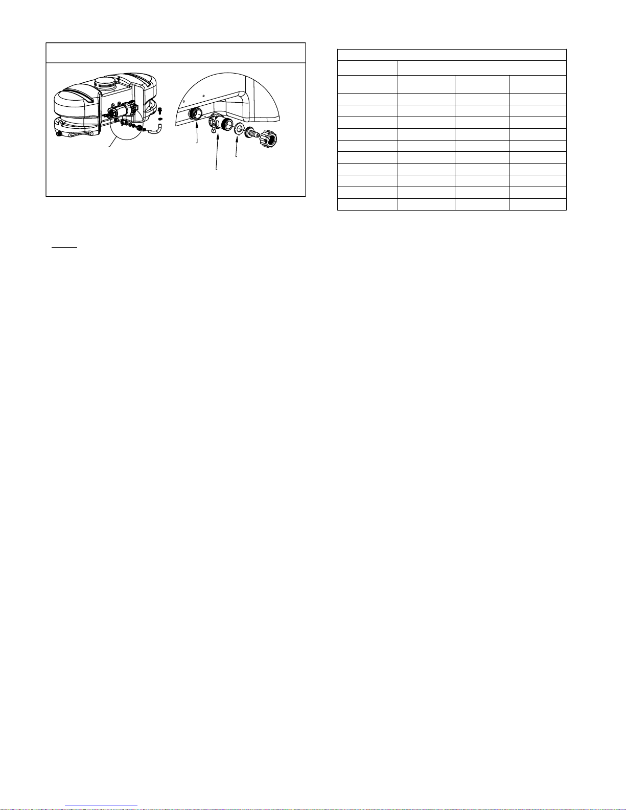
*** IMPORTANT REMINDER ***
A
This unit comes with an On/Off (shut-off)
valve located at the inlet location of the
tank, towards the underside. (See Detail A).
You must make sure the valve is in the
"open" position before using your unit.
Inlet from Tank
"ON/OFF" Valve
Detail A
Filter/Screen
Speed in M.P.H.
(Miles per Hour)
1.0
2.0
3.0
4.0
5.0
6.0
7.0
8.0
9.0
10.0
Speed Chart
Time Required in seconds to travel a distance of:
100 Ft.
68 sec.
34
23
14
11
9.7
8.5
7.6
6.8
200 Ft.
136 sec.
68
45
3417
27
23
19
17
15
14
300 Ft.
205 sec.
102
68
51
41
34
29
26
23
20
Testing the Sprayer
NOTE:
It is VERY important for you to test your sprayer with plain water
before actual spraying is attempted. This will enable you to
check the sprayer for leaks, without the possibility of losing any
expensive chemicals.
Add water to the tank & drive to the starting place for spraying. When
you are ready to spray, turn the boom valve to the "on" position. This
will start solution spraying from the tips of the boom. The pressure
will decrease slightly when the boom is spraying. Adjust the pressure
by turning the "ON/OFF" valve lever on the bypass line valve.
Read the operating instructions and Initially begin spraying by closing
the 'bypass' valve (this is the center ON/OFF valve located at the
center port of your manifold assembly) and opening the boom line
valve (this is the 'other' valve on the manifold). This will enable the air
in the line to be eliminated (purged) through all the tips, while building
pressure. When everything tests all right (no leaks, & good pressure),
add the desired chemicals to the mixture and water combination and
start your spraying operation. Adjust the pressure and spray as you
did in the testing procedure.
Conditions of weather and terrain must be considered when setting
the sprayer. Do not spray on windy days. Protective clothing must be
worn in some cases.
Be sure to read the chemical label(s) correctly!
Calibration
Chemical labels may show application rates in gallons per
acre, gallons per 1000 square feet, or gallons per 100
square feet. You will note that the tip chart shows all 3 of
these rating systems.
Once you know how much you are going to spray, then
determine (from the tip chart) the spraying pressure (PSI),
and the spraying speed (MPH).
Determining the proper speed of the pulling vehicle can be
done by marking off 100, 200, & 300 feet. The speed chart
indicates the number of seconds it takes to travel the
distances. Set the throttle and with a running start, travel the
distances. Adjust the throttle until you travel the distances in
the number of seconds indicated by the speed chart. Once
you have reached the throttle setting needed, mark the
throttle location so you can stop and go again, returning to
the same speed.
Add water and proper amount of chemical to the tank and
drive to the starting place for spraying.
Adjusting Pressure
- When the bypass valve is closed, pressure is at the highest
point.
- Opening the valve will decrease pressure.
Operation
Your sprayer is equipped with (2) ON/OFF switches. One is
on the wire assembly that you hook up to your battery, the
other is on the pump itself, on the opposite end of the
pressure switch. The "-" is the "ON" position and the "o" is
the "OFF" position for the switches. Make sure both
switches are depressed in the "-" position for operation.
In addition to the ON/OFF switch, the pump is equipped with
an electronic pressure switch that is factory pre-set for it to
shut off at 45 p.s.i.. This switch assembly is the 'square box'
on the head portion of the pump.
Always fill the tank with a desired amount of water first, and
then add the chemical slowly, mixing as you pour the
chemical into the tank. You may use the handgun to spray
into the solution in order to mix the chemical and water.
Initially begin spraying by opening the handgun. This will
enable the air in the line to be purged through the handgun
tip, while building pressure.
The pumping system draws solution from the tank, through
the strainer/filter, and to the pump. The pump forces the
solution under pressure to the handgun and/or boom
nozzles.
Open the handgun by squeezing the handle lever.
•
Rotating the adjustable nozzle tip on the handgun will
•
change the tip pattern from a straight stream to a cone
pattern (finer mist).
The pump's electronic pressure switch shuts the motor
•
off when all lines are closed. The system will remain
pressurized, and the pump motor will restart
automatically when either the handgun, or boom line is
opened. If the bypass line valve is in the open position,
the pump will not shut off automatically.
The (3) nozzles are fixed at 17 1/2" spacing.
•
All (3) nozzles spraying at the same time will allow a
•
maximum coverage of 30 feet.
The center nozzle will spray an 80" swath.
•
Each of the (3) nozzles has a shutoff valve, so you can
•
shut off each nozzle individually. This may help in
achieving the actual coverage needed for your
application.
When it becomes necessary to clean the screen, you will
need to shut off the ON/OFF valve down by the tank, on the
inlet side of the pump. Next, unscrew the knurled nut on the
outside of that valve. Remove the screen/washer which is
located in the knurled nut at that location. Rinse and tap out
the dirty screen and put back in it's original position when
clean. Do this on a regular basis to maintain a clean screen.
Page 2
Using the Boom Nozzles
After Spraying
Four things must be considered before spraying with the boom:
How much chemical must be mixed in the tank.
1.
Rate of spray (gallons per acre to be sprayed)
2.
What pressure (p.s.i.) will be used.
3.
Speed traveled (mph) while spraying.
4.
- Refer to the chemical label to determine your chemical mixture.
- See the tip chart to determine the pressure to be used. The chart
will also show the speed used when spraying.
- Start the pump and open the valve(s) to the boom nozzles.
- Check the spray pattern. Usually you can see the coverage better
on a solid concrete surface, such as a driveway.
- The boomless nozzles should be approx. 33" above the objects
being sprayed.
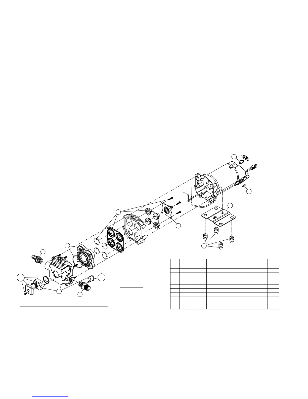
#5275704 Pump
(12 Volt, 11 Amp, 3.8 gpm, 45 psi)
After use, fill the sprayer tank part way with water. Start the
sprayer, and allow the clear water to be pumped through the
plumbing system and out through the spray nozzles.
Refill the tank about half full with plain water and use FIMCO
Tank Neutralizer and Cleaner, and repeat cleaning instructions
above.
Flush the entire sprayer with the neutralizing/cleaning agent,
then flush out one more time with plain water. Follow the
chemical manufacturer's disposal instructions of all wash or
rinsing water.
For the boom, (if applicable) remove the tips and screens from
the nozzle assemblies. Wash these items out thoroughly. Blow
the orifice clean and dry. If the orifice remains clogged, clean it
with a fine bristle (NOT WIRE) brush, or with a toothpick. Do
not damage the orifice. Water rinse and dry the tips before
storing.
WARNING: Some chemicals will damage the pump valves
if allowed to soak untreated for a length of time! ALWAYS
flush the pump as instructed after each use.
4
6
*
5.2
5
*
5.1
Troubleshooting a 3.8 g.p.m. Pump:
Pump will NOT run:
- Check inline fuse on the wires on the pump. If blown, replace with new fuse. (15 Amp mini-blade fuse #5157206)
- Make sure BOTH on/off switches are in the 'on' position (-).
- Make sure you 12 volt source (battery) is fully charged.
- Insure a tight connection at the battery clips.
If none of the above will work, try pulling wire terminal "A" off of the spade terminal of the pressure switch, and cross it over and touch terminal "B". (You will need to remove
the pressure switch cap before doing this) If your pump runs when you do this, you know you will need to replace your pressure switch.
Another thing you can try is to take apart the switch box on the lead wire assembly (#5274443) with the (2) phillips head screws, and 'hot-wire' it together. Take the (2) wires
that are screwed to the rocker switch, off of the switch and twist them together. This will insure you are getting the full 12 volts to the pump. If your pump runs after doing this,
you will know that your lead wire assembly needs to be replaced.
Pump runs, but does not prime:
- Check line strainer (screen) at the inlet location, at the tank. You will need to unscrew the knurled nut to access this screen. (see exploded view later in this manual) The
ON/OFF valve should be closed while performing this, to insure you do not lose any solution. Periodically take the screen at this location out and clean it.
- Make sure the bypass line valve is closed, to allow the pressure to build up in your system.
- Unscrew the head portion of your pump and remove the check valve assembly from inside. You need to make sure the O-Ring comes out with this piece as well. (See the
exploded view to help identify these components) These pieces can be cleaned which, in most cases, will help restore some, if not most, of your prime. Soak this check valve
in a solution of hot, soapy water. A good name-brand dishsoap works well for this. A little bit of 'scrubbing' with perhaps an old toothbrush may be required to actually break up
any build-up that may be on the check valve. Rinse off the pieces and replace them back into your pump. Reassemble the pump. Hook it back up and test.
7
Fittings with an asterisk (*) by
them, come together in a bag,
part #7771831.
(1) 5168832 - 1/2" MNPT
(1) 5168833 - 1/2" Hose Barb
"B"
"A"
8
Item
Part
No
Number
1
5029092
2
5075019
3
5157206
4
5157207
5
5168821
20408-000
5.1
5.2 5157203
5168824
6
7
5168826
5168828
8
1
2
Description
Qty
1
Base Plate (Quad Pump)
1
Pkg. (4) Grommets
1
15 Amp Mini Fuse
1
Rocker Switch
Upper Housing
1
1
Pkg. (2) Clips (Port Fitting)
1
Pressure Switch Assembly
1
Check Valve Kit w/O-Ring & Ferrules
1
Diaphragm Kit w/Pistons & (4) Screws
1
Cam/Bearing Kit, w/Set Screw
3
List
Price
9.62
3.11
4.15
7.27
41.55
3.55
24.91
25.99
20.76
13.47
Page 3
 Loading...