

Fimco LG-1500-303 Owner’s Manual
O NEEE vS
Model: LG-1500-303 (5301064)
(15 Gallon Lawn & Garden Trailer Sprayer)
IF YOU SHOULD HAVE A QUESTION OR
EXPERIENCE A PROBLEM WITH YOUR
FIMCO INDUSTRIES PRODUCT:
1-800-831-0027
BEFORE YOU CALL PLEASE HAVE THE
FOLLOWING INFORMATION AVAILABLE;
SALES RECEIPT & MODEL NUMBER. IN MOST
CASES_A FIMCO INDUSTRIES EMPLOYEE CAN
RESOLVE THE PROBLEM OVER THE PHONE,
Technical Specifications
15 Gal. Corrosion-Resistant Polyethylene Tank
12 Vott Diaphragm Pump, 2 1 g,p ,m,,- 60 p ,s,i,
Lever Handgun
15 Ft Handgun Hose
18 Ft. max, vedical throw, 30 FL max horizontal throw
Low Profile Trailer & Tank
4 .I013.,50x 4 Pneumatic Tires
Pressure Gauge
Adjustable Pressure
2-Nozzle Boom Assembly. 80" Coverage
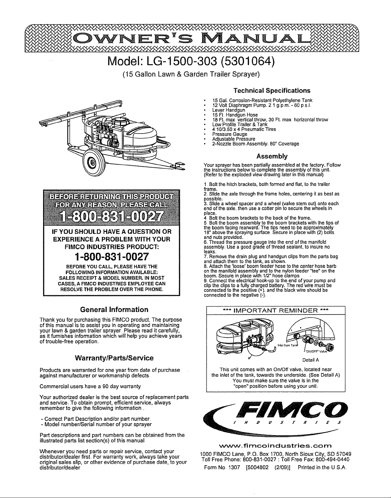
Assembly
Your sprayer has been partially assembled at the factory. Follow
the instructionsbelow to comprete the assembly of this uniL
(Refer to the exploded view drawing later in this manual)
t Bolt the hitchbrackets, both formed and flat, to the traitor
frame.
2, Slide the axle through the frame holes, centering it as best as
possible.
3. Slide a wheel spacer and a wheel (valve stem out) onto each
end of the axle. then use a cotter pin to secure the wheels in
place.
4 Bolt the boom brackets to the back of the frame.
5 Boil the boom assembly to the boom brackets with the tips of
the boom facing rearward, The tips need to be approximately
18" above the spraying surface, Secure in place with (2) bolts
and nuts provided,,
6. Thread the pressure gauge into the end of the manifold
assembly° Use a good grade of thread sealant, to insure no
leaks.
7, Remove the drain plug and handgun dips from the parts bag
and attach them to the tank, as shown,.
8. Attach the %ose' boom feeder hose to the center hose barb
on the manifold assembly and to the nylon feeder "tee" on the
boom. Secure in place with _12"hose clamps. .
9. Connect the electricar hook-up to the end of your pump and
clip the clips to a fully charged battery. The red wire must be
connected to the positive (+). and the black wire should be
connected to the negative (-),,
General Information
Thank you for purchasing this FIMCO product. The purpose
of this manual is to assist you in operating and maintaining
your lawn & garden trailer sprayer, Please read it carefully,
as it furnishes information which will help you achieve years
of trouble-free operation,
WarrantylPartslSer¢ice
Products are warranted for one year from date of purchase
against manufacturer or workmanship defects.
Commercial users have a 90 day warranty
Your authorized dealer is the best source of replacement parts
and service. To obtain prompt, efficient service, always
remember to give the following information ....
- Correct Part Description andlor part number,
- Model number/Serial number of your sprayer
Part descriptions and part numbers can be obtained from the
illustrated parts list section(s) of this manual,
Whenever you need parts or repair service, contact your
distributor/dealer first For warranty work, always take your
original sales slip, or other evidence of purchase date, to your
distdbutorldealer
*** IMPORTANT REMINDER ***
Detail A
This unit comes with an OntOff valve, located near
the inlet of the tank, towards the underside,, (See Detail A)
t000 FIMCO Lane, P,O. Box 1700, North Sioux City, SD 57049
Toil Free Phone: 800-831-0027 : Toll Free Fax: 800-494.0440
Form No, 1307 [5004802 (2!09)] Printed in the USoA,
You must make sure the valve is in the
"open" posilion before using your unit.
_._tww,,fi mco in d u stries, co m
Testing the Sprayer
NOTE:
_RY important for you to test your sprayer with
plain water before actual spraying is attempted_ This will
enable you to check the sprayer for leaks, without the
possibility of losing any expensive chemicals_
Add water to the tank & drive to the starting place for
spraying. _en you are ready to spray, turn the boom valve
to the "on' position. This will start solution spraying from the
tips of the boom. The pressure will decrease slightly when the
boom is spraying.. Adjust the pressure by turning the
"ONtOFF' valve lever on the bypass line valve.
Read the operating instructions and Initially begin spraying by
closing the 'bypass' valve (this is the center ON/OFF valve
located at the center port of your manifold assembly) and
opening the boom line valve (this is the 'other' valve on the
manifold). This will enable the air in the line to be eliminated
(purged) through all the tips, while building pressure When
everything tests al! right (no leaks, & good pressure), add the
desired chemicals to the mixture and water combination and
start your sprayingoperation Adjust the pressure and spray
as you did in the testing procedure.
Conditions of weather and terrain must be considered when
setting the sprayer. Do not spray on windy days,, Protective
clothing must be worn in some cases
Be sure to read the chemical label(s) correctlyl
WARNING: Some chemicals wilt damage the pump valves if
allowed to soak untreated for a length of time! ALWAYS
thoroughly flush the pump with water afteruse. DO NOT
allow chemicals to sit in the pump for extended times of
idleness. Follow the chemical manufacturer's instructions on
disposalof al!waste water from the sprayer
Operation
Your sprayer is equipped with (2) ONIOFF switches. One is
on the wire assembly that you hook up to your baflery, the
other is on the pump itself, on the opposite end of the
pressure switch. The "J' is the "ON" positionand the "o"is
the "OFF" position for the switches. Make sure both switches
are depressed in the "-" position for operation.
In addition to the ON/OFF switch, the pump is equipped with
an electronic pressure switch that is factory pre-set for it to
shut off at 60 ps.i.. This switch assembly is the 'square box'
on the head portion of the pump.
Always fill the tank with a desired amount of water first, and
then add the chemical slowly, mixing as you pour the
chemical into the tank. You may use the handgun to spray
into the solution in order to mix the chemical and water..
The pumping system draws solution from the tank, through
the strainerlfilter, and to the pump..The pump forces the
solution under pressure to the handgun andtor boom
no771es
• Open the handgun by squeezing the handle lever
- Rotating the adjustable nozzle tip on the handgun will
change the tip pattern from a straight stream to a cone
pattern (finer mist).
This sprayer is designed to be towed behind a garden
tractor..
The nozzles on the boom willspray an 80 inch wide swath
Check the nozzle pattern by spraying water on a concrete
surface Raise the boom to a higher mounting position to get
more spray pattern overlap, if desired.
Speed Chart
Time Required in seconds te travel a distance of:
Speed in M.P,H,
(Miles per Heur)
1.0
2,0
3,0
4.0
5.0
6.0 11 23 34
7.0 9.7 19 29
8.0 8.5 17 26
9.0 7.6 15 23
10,0 6,8 14 20
Tip Spray =ressure Capacity 1 2 3 4 5 7 5 10
No Height (psi) (GPM} MPH MF_ iMPH MPH MPH MPH MPH
3 18"
33p Spray !Pressure Capacity Gallons,,Per 1000 Sq Ft. _ Based en Waist
Ne Height (psi) (GF_')
3 18-
Tip Spray Pressure Capacity
Ne Height (ps_ (GRVQ
3 t8'"
100 Ft
68 sac.
34
23
17
14
10 30 44 22 149111 89 59 45
20 42 63 315 20gi 157 126 84 63
30 52 76 38 26 193 154 103 77
40 ,60 90 45 30 22 17.8 11.8 8.g
10 30 I 01 50 34 254 204 135 103
20 ,42 1 4 ,72 48 3S 29 19 14
30 52 174 87 596 44 35 236 ..176
40 ,60 2 06 1 00 ;688 50 408 2'7 20
10 30 ,10 05 034 025 02 013 01
20 ,42 ,14 072 D48 036 029 01g ,014
30 52 174 087 059 044 035 023 017
40 ,60 .205 .10 ,068 .05 ,04 .027 .02
200 Ft 30o FL
136 sec, 205 sec.
B8 102
45 68
34 51
27 41
Gallons Per Acre - Based On Wa_er
1 2 3 4 5 75 io
MPH MFH MFIt _ MPH MPH MPH
Gatlons Per 100 Sq, Ft, - Based on Water
1 2 3 4 5 75 10
MPH MFH MR"I MPH MF'H _ IViF'H
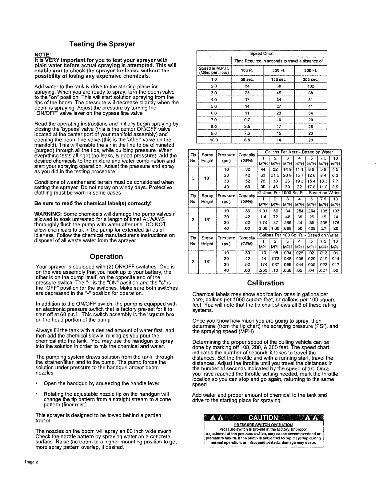
Calibration
Chemical labels may show application rates in gallons per
acre, gallonsper 1000 square feet, orgalions per 100 square
feet You wiltnote that the tip chart shows all 3 ofthese rating
systems..
Once you know how much you are going tospray, then
determine (from the tip chart) the spraying pressure (PSi), and
the spraying speed (MPH).
Determining the proper speed of the pulling vehicle can be
done by marking off 100, 200, & 300 feet. The speed chart
indicatesthe number of seconds it takes to travel the
distances. Set the throttle and with a running start, travel the
distances. Adjust the throttle until you travel the distances in
the number of seconds indicated by the speed chart. Once
_/oOUhave reached the throttle setting needed, mark the throttle
cation so you can stop and go again, reh_rning to the same
speed.
Add water and proper amount of chemical to the tank and
drive to the ,starting place for spraying,.
_BESSU_IE _WITC H
Pressure switch t= prms_ at the foolery, Improper
adjustment ef lhe pressure awttol_, may cause severe overload or
premature fallute_ If lhe pump Is subiected to rapid cydtng dudng
normal operation, or Infrt_laSnt perlod_ dsmmgs may occur,
Page 2
 Loading...