

Fimco ATV-25-71 Owner's Manual
OWNER’S MANUAL
Technical Specifications
25 Gal. Corrosion-Resistant Polyethylene Tank
12 Volt Diaphragm Pump, 3.8 g.p.m.—45 psi
15 Ft. Handgun Hose (3/8” I.D.)
26 Ft. Vertical throw, 35 Ft. Horizontal Throw
Pressure Gauge
7-Nozzle Deluxe Boom Assembly
(140” Spray Coverage)
Corrosion-Resistant Nylon Nozzles
Bypass (Recirculation) Line
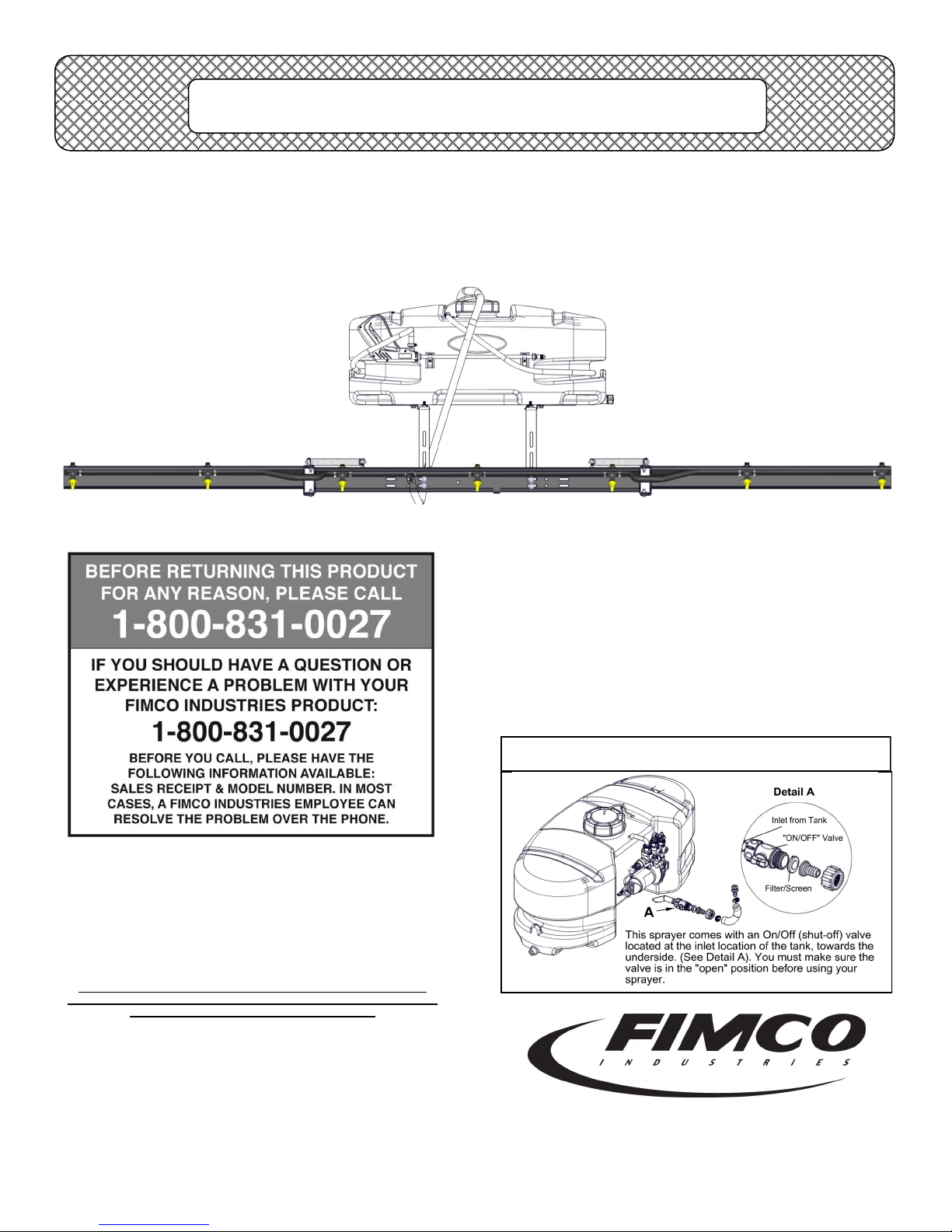
Model: ATV-25-71 (5301159)
(25 Gallon ‘Deluxe’ Lawn & Garden/ATV Sprayer)
Caution: Always check the vehicle
load rating before using this sprayer.
The loaded weight of the sprayer and
boom assembly is about 280 lbs.
when the tank is full. Care must be
taken not to tip the vehicle over backwards, especially when starting or
accelerating.
Assembly Instructions
Make sure the contents of the sprayer’s carton match the
items shown on page 2 of the manual.
Follow the steps on pages 3, 4 & 5 to properly assemble
the sprayer.
After assembly is complete and before testing your
sprayer, make sure you connect the electrical hook-up to
the end of your pump and clip the clips to a fully charged
battery. The red wire must be connected to the positive
(+) and the black wire should be connected to the negative (-).
The drain plug assembly should already be attached to
the tank
General Information
Thank you for purchasing this product. The purpose of this
manual is to assist you in operating and maintaining your lawn
& garden/ATV sprayer. Please read it carefully, as it furnishes
information which will help you achieve years of trouble-free
operation.
Warranty
Products are warranted for one year from date of purchase
against manufacturer or workmanship defects for home owner
www.fimcoindustries.com or call: TOLL FREE @ 1-800-831-0027
Our Technical Support Representatives will be happy to help you.
To obtain prompt, efficient service, always remember to give the
Part descriptions and numbers can be obtained from the illustrated
usage and 90 days for commercial usage.
For technical assistance, visit our website @
following information…
Correct Part Description and/or part number
Model #/Serial # of your sprayer
parts list section(s) of this manual.
***IMPORTANT REMINDER***
www.fimcoindustries.com
1000 FIMCO Lane, P.O. Box 1700, North Sioux City, SD 57049
Toll Free Phone: 800-831-0027 : Toll Free Fax: 800-494-0440
[5004550 (06/15)]
Page 1
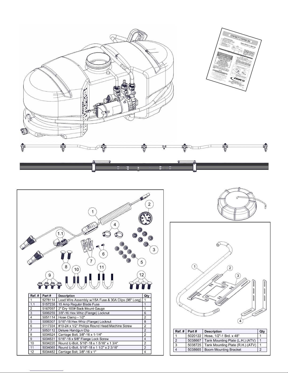
Contents of your sprayer’s carton (ATV-25-71 - 5301159):
Owner’s
Manual
Tank/Plumbing Pre-Assembly
7-Nozzle Boom (5274770) & 7-Nozzle Harness (#5277765)
Contents of Parts Bag
#5278307
Tank Lid &
Lanyard
(#5058188)
Contents of Bracket Kit
#5275935
Page 2
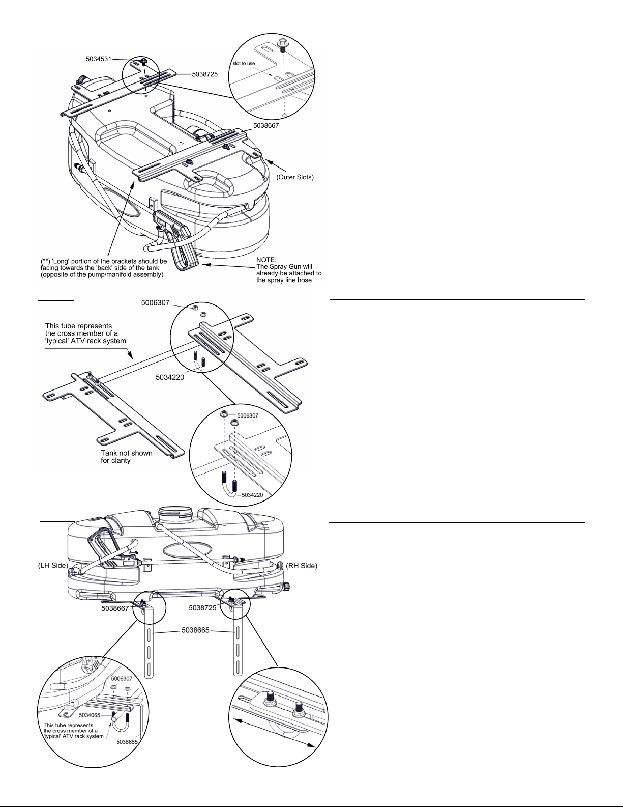
Step 1
Step 2
Step 3
Assembly Procedure (ATV-25-71)
Normally, the sprayer will be mounted on an ATV with the
pump assembly at the operator’s back and the spray wand
will be at the rear of the unit. Right Hand (RH) and Le
Hand (LH) sides of the sprayer are determined as if you are
standing behind the sprayer, looking at it (facing forward)
Aer removing the tank from the box, start the assembly
procedure by turning the tank upside on a stable, at surface.
A 1/2” socket or wrench is required for this step.
(**) Mount tank brackets (LH: 5038667) & (RH: 5038725) to
the underside of the tank as shown in Step 1. Use (4) bolts
(5034531) to secure it to the tank. The tank will rest on the
surface of the brackets which have the six small slots. You
will not be using the two outer slots on each bracket, as
they are used for other sprayers. Make sure the brackets
are parallel with each other before ghtening down the
bolts. Do not over-ghten.
Aer all the brackets are securely aached, you are now
ready to mount this to an ATV rack system. Remember that
all rack systems are not alike and this was designed to t
‘most’ rack systems. There is a chance it may not t your
parcular rack.
It may be benecial to have a helper or 2nd person, while
doing this step. Place the sprayer on to the ATV rack and
nd the most opmal place for the u-bolts to aach
through the rack and then through the long slots on the
tank brackets. Once the posion is determined, feed the ubolts (5034220) up from the underside of the rack and
secure in place with the whiz nuts (5006307). Make sure
the threads of the u-bolts do not puncture the tank at any
point. Manually adjust the u-bolts slightly if they get too
close to the tank. Do this prior to fully ghtening the
brackets to the rack.
A 1/2” socket or wrench is required for this step.
A 1/2” socket or wrench is required for this step.
Once the posion is determined, feed the u-bolts
(5034065) up from the underside of the rack through the
RH & LH tank mounng brackets and the boom mounng
brackets (5038665) and secure in place with the whiz nuts
(5006307). You can posion them as needed within the slot
on the tab. Make sure the threads of the u-bolts do not
puncture the tank at any point. Manually adjust the u-bolts
slightly if they get too close to the tank. Do this prior to
fully ghtening the brackets to the rack.
Detail A shows the (RH side) bracket in the ‘middle’ of the
slot. If you were to posion this bracket at this locaon,
make sure the LH side bracket is posioned in the same
posion.
Detail A
Page 3
 Loading...