

Fimco ATV-20-2-QR Owner's Manual
OWNER’S MANUAL
Model: ATV-20-2-QR (5302319)
(15 Gallon Lawn & Garden/ATV Sprayer)
Technical Specifications
x 20 Gal. Corrosion-Resistant Polyethylene Tank
x 12 Volt Diaphragm Pump, 2.1 g.p.m.—60 psi
x 15 Ft. Handgun Hose (3/8” I.D.)
x 15 Ft. Vertical throw, 30 Ft. Horizontal Throw
x Pressure Gauge
x 2-Nozzle Boom Assembly (80” Spray Coverage)
x Corrosion-Resistant Nylon Nozzles
x Pressure Adjust (recirculation) Line
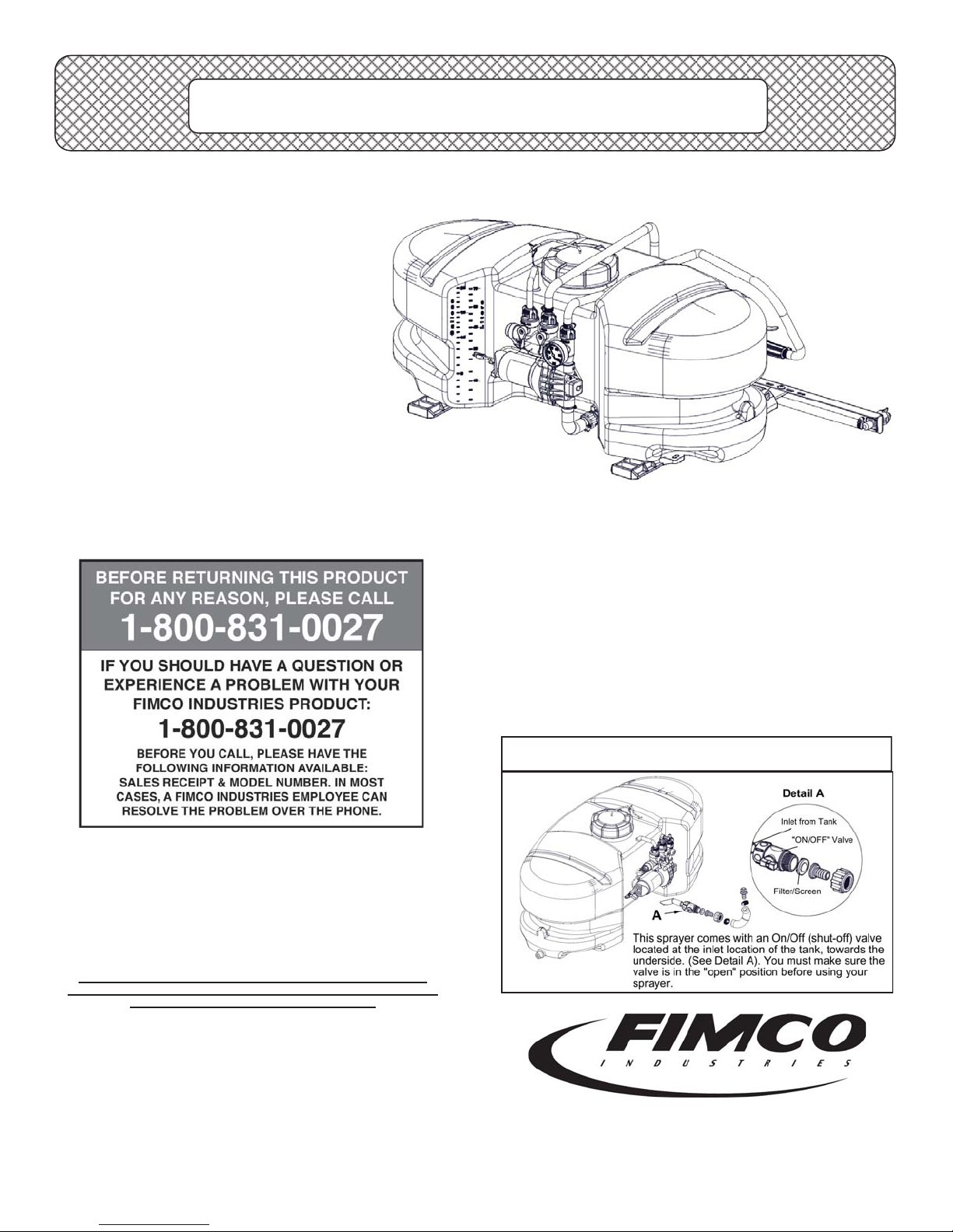
This sprayer may be mounted to most makes
of agricultural ATV vehicles.
Caution: When fully filled with water, this sprayer
will weigh 205 lbs.. Consult the owner’s manual for
your vehicle to verify that you are within it’s load
carrying capacity.
Assembly Instructions
x Make sure the contents of the sprayer’s carton match the
items shown on page 2 of the manual.
x Follow the steps on pages 3 & 4 to properly assemble
the sprayer.
x After assembly is complete and before testing your
sprayer, make sure you connect the electrical hook-up to
the end of your pump and clip the clips to a fully charged
battery. The red wire must be connected to the positive
(+) and the black wire should be connected to the negative (-).
x The drain plug assembly should already be attached to
the tank
General Information
Thank you for purchasing this product. The purpose of this
manual is to assist you in operating and maintaining your lawn
& garden/ATV sprayer. Please read it carefully, as it furnishes
information which will help you achieve years of trouble-free
operation.
Warranty
Products are warranted for one year from date of purchase
against manufacturer or workmanship defects for home owner
www.fimcoindustries.com or call: TOLL FREE @ 1-800-831-0027
Our Technical Support Representatives will be happy to help you.
To obtain prompt, efficient service, always remember to give the
Part descriptions and numbers can be obtained from the illustrated
usage and 90 days for commercial usage.
For technical assistance, visit our website @
following information…
x Correct Part Description and/or part number
x Model #/Serial # of your sprayer
parts list section(s) of this manual.
***IMPORTANT REMINDER***
www.fimcoindustries.com
1000 FIMCO Lane, P.O. Box 1700, North Sioux City, SD 57049
Toll Free Phone: 800-831-0027 : Toll Free Fax: 800-494-0440
[5008433 (04/16)]
Page 1
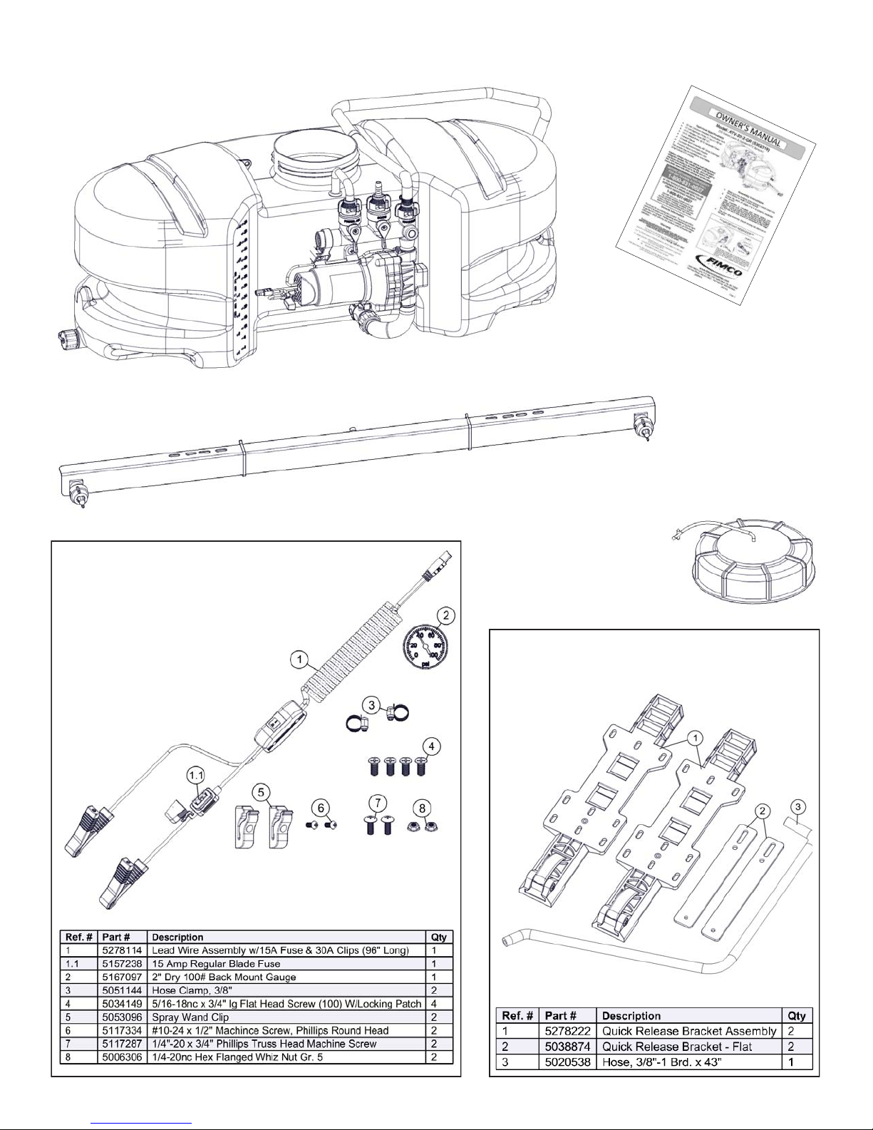
Contents of your sprayer’s carton (ATV-20-2-QR):
Owner’s
Manual
Tank/Frame Pre-Assembly
Contents of Parts Bag
#5278139
2-Nozzle Rigid Boom (#5278237)
Tank Lid
& Lanyard
(#5058188)
Contents of Bracket Kit
#5278140
Page 2

Step 1
Step 2
Assembly Procedure (ATV-20-2-QR)
Normally, the sprayer will be mounted on an ATV with the
pump assembly at the operator’s back and the spray wand
will be at the rear of the unit. Right Hand (RH) and Left Hand
(LH) sides of the sprayer are determined as if you are standing behind the sprayer, looking at it (facing forward)
After removing the tank from the box, start the assembly
procedure by turning the tank upside on a stable, flat surface.
A phillips head screwdriver is required for this step.
(**) Mount the tank brackets (5278222) to the underside of
the tank as shown in Step 1. Use (4) flat head screws
(5034149) to secure it to the tank. The tank will rest on the
surface of the brackets. Make sure the brackets are parallel
with each other before tightening down the bolts. Do not over
-tighten.
After your tank brackets are secured to the tank, turn the
tank assembly over and position it so that the cam handles
which extend beyond the back of the tank are facing you and
just hanging over the edge of the table or flat surface you are
assembling this on.
Secure the boom mounting brackets (5038874) to the tank
mounting brackets with Cam handles as shown in Detail A.
You can position them as needed within the slot on the
bracket. Just be sure that the surfaces of both brackets are
even with each other.
Step 3
Detail
B
Detail A
A phillips head screwdriver is required for this step.
Attach the 2-nozzle harness to the boom sub-assembly.
The end (elbow) nozzle assemblies slide into the cutout of
the horizontal brackets.
Use 2 plastic retaining clips to hold in place. (Detail B)
Once the nozzles are in the cutouts, slide each clip in the
gap between the steel bracket and the plastic nozzle. These
can be mounted on the front or rear side of the bracket.
These should ‘snap’ in place and hold the nozzle securely.
Attach the boom assembly to the boom mounting brackets,
making sure the boom is centered. Secure in place with (2)
phillips head screws (5117287) and (2) whiz lock nuts
(5006306).
You are now ready to mount this unit to an ATV, using ratchet straps (NOT INCLUDED).
Page 3
 Loading...