

Fimco 200-3PT-1PC-TSC Owner's Manual
OWNER’S MANUAL
Model: 200-3PT-1PC-TSC (2152285)
(200 Gallon 3-Point Sprayer w/8-Row Boom, Handgun, Pump & Coupler)
Category I or II
1. Install the tee valve sub-assembly to the 3-point carrier valve
Assembly Instructions
mount and position as shown in the exploded view.
2. Slip the 1/2” bypass hose (from the relief valve) over the fitting
on the bottom of the tank. Slide the hose clamp to the end of the
hose and secure.
General Information
Thank you for purchasing this product. The purpose of this
manual is to assist you in operating and maintaining your
3-Point Sprayer.
Retain a copy of your receipt for your unit,
as it will be required to validate any warranty service
Products are warranted against manufacturer or workmanship
defects for one year from date of purchase for home owner
usage and 90 days for commercial usage.
For technical assistance, visit our website @
www.fimcoindustries.com or call: TOLL FREE @ 1-800-831-0027
Our Technical Support Representatives will be happy to help you.
To obtain prompt, efficient service, always remember to give the
following information…
Correct Part Description and/or part number
Model #/Serial # of your sprayer
Part descriptions and numbers can be obtained from the illustrated
parts list section(s) of this manual.
3. Find the 1” x 36” pump feeder hose. Using a good quality
thread sealant, carefully thread the 1” fitting into the strainer
and the 3/4” fitting into the inlet side of the pump. Slip the hose
all the way onto the fittings and secure with the hose clamps.
4. Attach the 3/4” hose coming off the valve assembly to the out-
put side of the pump by threading the 3/4” fitting into the pump
and securing with the hose clamp. Remember to use sealant.
5. The roller pump IS included with the assembly. Attach the
adapter, the torque chain and S-hook to a pump as needed. It is
intended for your pump to be mounted directly to the tractor
PTO. The torque chain needs to be secured to the tractor to
keep your pump from spinning.
6. Wrap the handgun hose around the hose hangers, which are
attached to the tank straps.
7. Using sealant thread the gauge into the top of the tee valve
assembly.
8. Mount the upright angles to the inside of the mounts on the 3point carrier using the supplied 1/2” bolts and nuts. Attach the
backrack to the upright angles using the square U-bolts and
nuts. Note: the backrack can be mounted in either a high or low
position and the uprights can be adjusted for desired height.
Attach the U-brackets as shown.
9. Loosen the eye bolts and remove the 7” hinge bolts. Line up the
outer booms and reassemble the hinge bolt through the outer
boom yoke, the hinge casting and the spring connector. Tighten
the eye bolt until the spring is at the desired tension. Lock the
eye bolt in place with the inner whiz flange locknut. Bolt on the
boom extensions using the 3/8” x 1-3/4” bolts and hex lock nuts.
10. Hook an end of each boom chain on an “S” hook attached to
the top bar tube. Slip a slide clamp onto each outer boom.
Place the other end of the boom chain between the ears of the
slide clamp and secure with a 3/8” x 1” flange screw. Level the
outer booms by moving the slide clamps in or out as needed.
Tighten the bolts in the slide clamps to hold the clamps in place.
11. Attach the appropriate hose assemblies onto each of the three
boom sections. The center section as five nozzles with “L” connectors on each end.
12. Join the designated feeder hose from the tee valve subassembly to each boom section and secure in place with hose
clamps.
www.fimcoindustries.com
1000 FIMCO Lane, P.O. Box 1700, North Sioux City, SD 57049
Toll Free Phone: 800-831-0027 : Toll Free Fax: 800-494-0440
[5008067 (01/19)]
Page 1

Speed in M.P.H.
(Miles Per Hour)
100 Ft. 200 Ft. 300 Ft.
1.0 68 sec. 136 205
2.0 34 68 102
3.0 23 45 68
4.0 17 34 51
5.0 14 27 41
6.0 11 23 34
7.0 9.7 19 29
8.0 8.5 17 26
9.0 7.6 15 23
10.0 6.8 14 20
Speed Chart
Time Required in seconds to travel a distance of
Weight of Solution
Specific
Gravity
Conversion
Factors
7.0 lbs. per gallon
.84 .92
8.0 lbs. per gallon
.96 .98
8.345 lbs. per gallon
(Water)
1.00 1.00
9.0 lbs. per gallon
1.08 1.04
10.0 lbs. per gallon
1.20 1.10
10.66 lbs. per gallon
(28% Nitrogen)
1.28 1.13
11.0 lbs. per gallon
1.32 1.15
12.0 lbs. per gallon
1.44 1.20
14.0 lbs. per gallon
1.68 1.30
Spray
Angle
20"
Spacing
30"
Spacing
40"
Spacing
TeeJet (Flat Spray) 65° 22"-24" 33"-35" NR*
TeeJet (XR TeeJet) 80° 17"-19" 26"-28" NR*
TeeJet (XR TeeJet) 110° 12"-14" 16"-18" NR*
FloodJet 120° *** *** ***
* Not Recommended
*** Wide Angle Spray Tip is influenced by nozzle orientation.
The critical factor is to achieve a double spray patter overlap.
Suggested Minimum Spray Heights
Nozzle Type
Nozzle Height
1
MPH2MPH3MPH4MPH5MPH6MPH8MPH
15 .18 53.6 26.8 17.8 13.4 10.7 8.9 6.7
20 .21 62.4 31.2 20.8 15.6 12.5 10.4 7.8
30 .26 77.2 38.6 25.8 19.3 15.4 12.9 9.7
40 .30 88.0 44.0 29.8 22.0 17.8 14.9 11.1
1
MPH2MPH3MPH4MPH5MPH6MPH8MPH
15 .18 .61 .41 .31 .24
20 .21 .71 .48 .36 .29
30 .26 .88 .59 .44 .35
40 .30 1.0 .68 .51 .41
AIXR11003VP
Spray Tip Rate Chart (20" Spacing)
Tip
No.
Pressure
(psi)
Capacity
(GPM)
Gal. Per Acre - Based on Water
Tip
No.
Pressure
(psi)
Capacity
(GPM)
Gal. Per 1000 Sq. Ft. - Based on Water
AIXR11003VP
Roller pumps are positive displacement pumps, which means that
the entire solution being pumped must go somewhere or the pump
will break. In this roller pumping system, solution is drawn from the
tank and forced to a planned source, such as boom nozzles or handgun. The pressure is controlled by a pressure relief valve, which is a
spring-loaded device that controls the amount of fluid bypassed
(recirculated) to the tank. The gray handle is to be tightened to increase pressure and loosened to decrease pressure.
The ‘directo-valve’ is the on/off control which allows the operator to
manually control the solution going to the boom.
IMPORTANT: Remove tank lid and be sure the tank is
Information About the Sprayer
clean and free of any foreign material. Rinse tank out of any
tank residue before filling with water to test.
Tip Information
Important note about tips: When you refer to the rate charts found
in this owners manual, these rates are based on water. Please read
this tip selection section carefully before attempting to operate your
boom assembly.
The selection of proper tips for the boom is determined by the gallon
per acre (GPA) requirement which is specified on the chemical label.
The following characteristics also have a determining factor and must
be considered.
1. Speed of spraying (MPH).
2. Boom nozzle spacing (specified in inches).
3. Solution weight and conversion factor (CF)
4. Gallons of solution to be sprayed per acre.
5. Spraying pressure.
Useful Formulas:
GPM = Gallons Per Minute
GPA = Gallons Per Acre
MPH = Miles Per Hour
Calibration
Chemical labels may show application rates in gallons per acre, gallons per 1000 square feet or gallons per 100 square feet. You will
note that the tip chart (later in this manual) shows 2 of these rating
systems. Once you know how much you are going to spray, then
determine (from the tip chart) the spraying pressure (PSI), and the
spraying speed (MPH).
Determining the proper speed of the pulling vehicle can be done by
marking off 100, 200 & 300 feet. The speed chart indicates the number of seconds it takes to travel the distances. Set the throttle and
with a running start, travel the distances. Adjust the throttle until you
travel the distances in the number of seconds indicated by the speed
chart. Once you have reached the throttle setting needed, mark the
throttle location so you can stop and go again, returning to the same
speed.
Add water and proper amount of chemical to the tank and drive to the
starting place for spraying
Page 2
Four things must be considered before spraying with the boom.
Using the Boom Nozzles
How much chemical must be mixed in the tank.
Rate of spray (gallons per acre to be sprayed).
What pressure (p.s.i.) will be used.
Speed traveled (mph) while spraying.
Refer to the chemical label to determine your chemical mixture
See the tip chart to determine the pressure to be used. The
chart will also show the speed used when spraying.
Start the pump and open the valve to the boom nozzles.
Check the spray pattern. Usually you can see the coverage
better on a solid concrete surface, such as a driveway.
Spraying Solutions Other Than Water
Since all the tabulations are based on spraying water, which weighs
8.34 lbs. per USA gallon, conversion factors must be used when
spraying solutions which are heavier or lighter than water. To determine the proper size nozzle for the solution to be sprayed, first multiply the desired GPM or GPA of solution by the rate conversion factor.
Then use the new converted GPM or GPA rate to select the proper
size nozzle.
Example: Desired application rate is 20 GPA of 28% Nitrogen.
Determine the correct nozzle size as follows:
GPA (Solution) x Conversion Factor = GPA
20 GPA (28%) x 1.13 + 22.6 GPA (Water)
The applicator should choose a nozzle size that will supply 22.6 GPA
of water at the desired pressure.
Miscellaneous Conversion Factors
One Acre = 43,560 square feet = 0.405 Hectare
One Hectare = 2.471 Acres
One Gallon Per Acre = 9.35 Liters Per Hectare
One Mile = 5,280 Feet = 1,610 Meters = 1.61 Kilometers
One Gallon = 128 Fluid Ounces = 8 Pints = 4 Quarts = 3.79 Liters =
0.83 Imperial Gallons
One Pound Per Square Inch = 0.069 bar. = 6.895 Kilopascals
One Mile Per Hour = 1.609 Kilometers Per Hour
Higher pressure not only increases the flow rate of the nozzle, but it
also influences the droplet size and the rate of orifice wear. As pressure is increased, the droplet size decreases and the rate of orifice
wear is increased.
The values given in the tabulation section of this owners manual
indicate the most commonly used pressure ranges for the associated
spray tips.
Attach the sprayer to the tractor 3 point hitch. Mount the pump to the
PTO and affix the torque chain.
NOTE: It is important for to test your sprayer with plain water before
actual spraying is attempted. This will enable you to familiarize yourself and check for leaks without the possibility of losing any expensive chemicals.
Fill the tank about 1/2 full with plain water.
Before starting, open the suction line valve (located underneath the
carrier frame), turn the relief valve handle out to lower the line pressure. This will help prime the pump.
CAUTION: Always be sure that the water (or solution) has reached
the pump before starting your sprayer. If the pump is allowed to run
dry, serious damage to the pump will result.
Always have the pressure line open to the tips so that the air which
may be trapped in the line will be forced (or purged) out.
Start the tractor PTO. Check the entire system for leaks. Once the
pump is primed, the pressure may be increased by turning the handle of the pressure relief valve in. Keep the pressure line open to the
tips when setting the pressure. Set the pressure and then lock the
relief valve handle in place. Shut off the directo-valve and check for
leaks again. Pressure will increase when the pressure line valve is
closed and then return to the preset pressure when the valve is
opened again.
During the testing period, be sure to observe the spray pattern given
by the spray nozzles. If there is any pattern distortion, it will be
necessary to remove and clean the affected tips.
Caution: Never use a metal object or other sharp item for cleaning a
nozzle tip. It is better to use a nozzle brush (NOT wire brush) or
compressed air for tip cleaning.
Conditions of weather and terrain must be considered when setting
the sprayer. Do not spray on windy days. Protective clothing must be
worn in some cases
Be sure to read the chemical label(s) before application!
Operation
Testing the Sprayer
The performance of any agricultural chemical depends upon the
proper application.
Always fill the tank with a desired amount of water first and then add
the chemical slowly, mixing as you pour the chemical into the tank.
You may use the handgun to spraying into the solution in order to
mix the chemical and water.
The tips supplied as standard with the sprayer can be used for a
wide variety of spraying applications. Other tip sizes are available for
different coverages. The speed and pressure charts shown indicate
the rates can be changed considerably by changing speed and
pressure. The pumping system draws solution from the tank through
the strainer/filter and to the pump. The pump forces the solution
under pressure to the boom nozzles.
Tank Care & Maintenance
Warning: Do not use the tank as a container for fuel oils, kerosene,
gasoline or any other petroleum distillate product. All polyolefins are
softened and permeated by such products. In an enclosed area the
vaporization of these materials from the outside surface of the tank
could create a dangerous condition.
The tank should not be used as a pressure vessel nor used with
chemicals or solutions having a weight of more than 12 pounds per
gallon.
Store the tank in a dry dark place when not in use. Storage out of
sunlight will prolong the life of the tank.
Do not drop, strike or kick the tank, especially at low temperatures.
Tanks become brittle and are subject to cracking at temperatures
below 20° Fahrenheit.
Maintenance During/After Spraying
Periodically close the suction line valve and check the strainer and
clean the screen.
Proper care and maintenance will prolong the life of your sprayer.
After use, fill the sprayer tank part way with water. Start the sprayer
and allow the clear water to be pumped through the plumbing system
and out through the spray nozzles. Refill the tank about half full with
plain water and use FIMCO Tank Neutralizer and Cleaner and repeat
cleaning instructions above (If no tank cleaner is available, you may
substitute dish soap for this step, about 1-2 oz. per gallon). Flush the
entire sprayer with the neutralizing/cleaning agent, then flush out one
more time with plain water. Follow the chemical manufacturer’s disposal instructions of all wash or rinsing water. For the boom (if applicable) remove the tips and screens from the nozzle assemblies.
Wash these items out thoroughly. Blow the orifice clean and dry. If
the orifice remains clogged, clean it with a fine bristle (NOT WIRE)
brush or with a toothpick. Do not damage the orifice. Water rinse and
dry the tips before storing.
WARNING: Some chemicals will damage the pump valves if
allowed to soak untreated for a length of time! ALWAYS flush the
pump as instructed after each use. DO NOT allow chemicals to sit in
the pump for extended times of idleness. Follow the chemical manufacturer’s instructions on disposal of all waste water from the sprayer.
Winter Storage
Drain all water out of your sprayer, paying special attention to the
pump, handgun and valve(s). These items are especially prone to
damage from chemicals and freezing weather.
The sprayer should be winterized before storage by pumping a solution of automotive antifreeze (containing a rust inhibitor) through the
entire plumbing system. This antifreeze solution should remain in the
plumbing system during the winter months. When spring time comes
and you are preparing your sprayer for the spray season, rinse the
entire plumbing system out, clearing the lines of the antifreeze solution. Proper care and maintenance will prolong the life of your
sprayer.
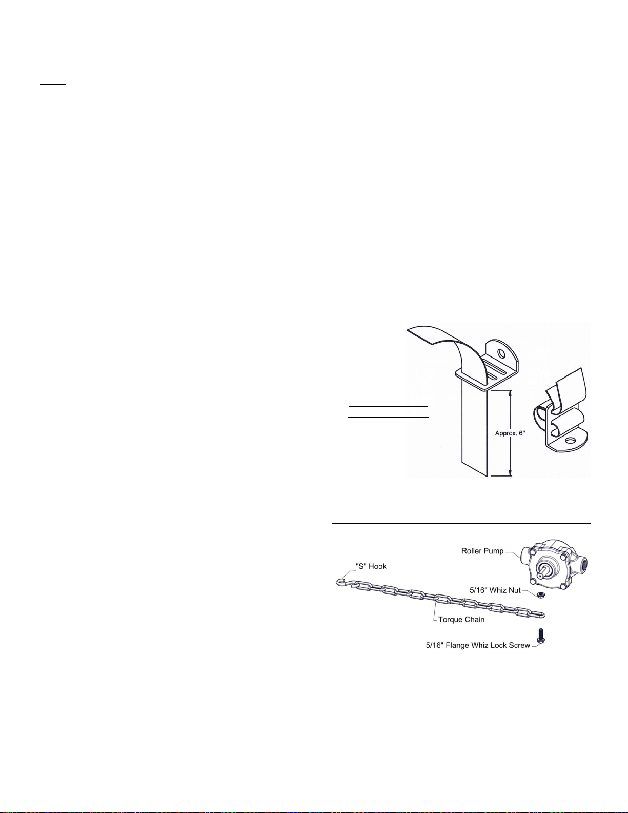
Strap/Buckle Detail
Strap Attachment
to a “Bent” Buckle
The nylon straps are to be inserted in and out of the slots in the
buckle, as shown. Be sure the straps are snug before tightening the
hook bolts. In most cases, it will be necessary to re-tighten the straps
after filling the tank with liquid.
Torque Chain Attachment to a Roller Pump
A torque chain, ‘S’ hook, nut and bolt are included in this assembly to
secure your pump during operation.
1. Attach one end of the torque chain over the threaded stem of the
bolt
2. Thread the whiz nut onto the bolt. Hand-tighten
3. Thread the bolt, chain and nut ‘pre-assembly’ into the threaded
hole on the underside of the pump. Tighten sufficiently
4. Affix the ‘S’ Hook to your frame (or hitch). Wrap the chain around
the frame or hitch and ‘S-Hook’ it in place. Make sure this connection is very secure! Not having a good, tight connection may
result in the pump spinning on your PTO shaft and damaging
some components of your sprayer
*** Insure that this connection point will not allow the roller pump to
spin on the PTO shaft ***
Page 3
 Loading...