

Fimco 110-3PT-BB-TSC, 200-3PT-BB-TSC Owner's Manual
OWNER’S MANUAL
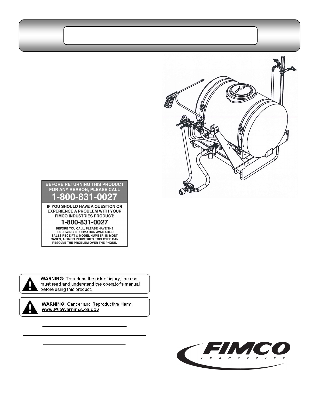
Model: 110-3PT-BB-TSC
(2152277)
(110 Gallon 3-Point Sprayer
w/Boom-Buster ’Boomless’ Boom Assembly
& Handgun)
(Pump & Coupler Included)
General Information
Thank you for purchasing this product. The purpose of this
manual is to assist you in operating and maintaining your
3-Point Sprayer.
Retain a copy of your receipt for your unit,
as it will be required to validate any warranty service
Products are warranted against manufacturer or workmanship
defects for one year from date of purchase for home owner
usage and 90 days for commercial usage.
For technical assistance, visit our website @
www.fimcoindustries.com or call: TOLL FREE @ 1-800-831-0027
Our Technical Support Representatives will be happy to help you.
To obtain prompt, efficient service, always remember to give the
following information…
Correct Part Description and/or part number
Model #/Serial # of your sprayer
Part descriptions and numbers can be obtained from the illustrated
parts list section(s) of this manual.
Category I or II
Assembly Instructions
1. Install the directo valve sub-assembly to the 3-point carrier valve
mount and position as shown in the exploded view.
2. Slip the 5/8” bypass hose (from the relief valve) over the fitting
on the bottom of the tank. Slide the hose clamp to the end of the
hose and secure.
3. Find the 1” x 36” pump feeder hose. Using a good quality thread
sealant, carefully thread the 1” fitting into the strainer and the
3/4” fitting into the inlet side of the pump. Slip the hose all the
way onto the fittings and secure with the hose clamps.
4. Attach the 3/4” hose coming off the valve assembly to the output
side of the pump by threading the 3/4” fitting into the pump and
securing with the hose clamp. Remember to use sealant.
5. The roller pump is included with the assembly. Attach the
adapter, the torque chain and S-hook to a pump as needed. It is
intended for your pump to be mounted directly to the tractor
PTO. The torque chain needs to be secured to the tractor to
keep your pump from spinning.
6. Wrap the handgun hose around the hose hangers, which are
attached to the tank straps.
7. Remove the plug from the top of the directo valve and using
sealant, thread the gauge into the valve.
8. Attach the boom buster bracket to the telescoping brackets,
using the two 3/8” square u-bolts and whiz nuts. The telescoping
brackets are already mounted on the 3-point frame.
9. Slide the boom buster subassembly onto the boom buster brack-
et. Set the desired height with the handle screw.
10. Secure the two 1/2” x 96” hoses to the boom buster subassem-
bly with the hose clamps.
www.fimcoindustries.com
1000 FIMCO Lane, P.O. Box 1700, North Sioux City, SD 57049
Toll Free Phone: 800-831-0027 : Toll Free Fax: 800-494-0440
[5008038 (01/19)]
Page 1

Speed in M.P.H.
(Miles Per Hour)
100 Ft. 200 Ft. 300 Ft.
1.0 68 sec. 136 205
2.0 34 68 102
3.0 23 45 68
4.0 17 34 51
5.0 14 27 41
6.0 11 23 34
7.0 9.7 19 29
8.0 8.5 17 26
9.0 7.6 15 23
10.0 6.8 14 20
Speed Chart
Time Required in seconds to travel a distance of
Weight of Solution
Specific
Gravity
Conversion
Factors
7.0 lbs. per gallon
.84 .92
8.0 lbs. per gallon
.96 .98
8.345 lbs. per gallon
(Water)
1.00 1.00
9.0 lbs. per gallon
1.08 1.04
10.0 lbs. per gallon
1.20 1.10
10.66 lbs. per gallon
(28% Nitrogen)
1.28 1.13
11.0 lbs. per gallon
1.32 1.15
12.0 lbs. per gallon
1.44 1.20
14.0 lbs. per gallon
1.68 1.30
Roller pumps are positive displacement pumps, which means that
the entire solution being pumped must go somewhere or the pump
will break. In this roller pumping system, solution is drawn from the
tank and forced to a planned source, such as boom nozzles or handgun. The pressure is controlled by a pressure relief valve, which is a
spring-loaded device that controls the amount of fluid bypassed
(recirculated) to the tank. The gray handle is to be tightened to increase pressure and loosened to decrease pressure.
The ‘directo-valve’ is the on/off control which allows the operator to
manually control the solution going to the boom.
IMPORTANT: Remove tank lid and be sure the tank is
Information About the Sprayer
clean and free of any foreign material. Rinse tank out of any
tank residue before filling with water to test.
Testing the Sprayer
Attach the sprayer to the tractor 3 point hitch. Mount the pump to the
PTO and affix the torque chain.
NOTE: It is important for to test your sprayer with plain water before
actual spraying is attempted. This will enable you to familiarize
yourself and check for leaks without the possibility of losing any
expensive chemicals.
Fill the tank about 1/2 full with plain water.
Before starting, open the suction line valve (located underneath the
carrier frame), turn the relief valve handle out to lower the line
pressure. This will help prime the pump.
CAUTION: Always be sure that the water (or solution) has reached
the pump before starting your sprayer. If the pump is allowed to run
dry, serious damage to the pump will result.
Always have the pressure line open to the tips so that the air which
may be trapped in the line will be forced (or purged) out.
Start the tractor PTO. Check the entire system for leaks. Once the
pump is primed, the pressure may be increased by turning the handle of the pressure relief valve in. Keep the pressure line open to the
tips when setting the pressure. Set the pressure and then lock the
relief valve handle in place. Shut off the directo-valve and check for
leaks again. Pressure will increase when the pressure line valve is
closed and then return to the preset pressure when the valve is
opened again.
During the testing period, be sure to observe the spray pattern given
by the spray nozzles. If there is any pattern distortion, it will be
necessary to remove and clean the affected tips.
Caution: Never use a metal object or other sharp item for cleaning a
nozzle tip. It is better to use a nozzle brush (NOT wire brush) or
compressed air for tip cleaning.
Conditions of weather and terrain must be considered when setting
the sprayer. Do not spray on windy days. Protective clothing must be
worn in some cases
Be sure to read the chemical label(s) before application!
Operation
The performance of any agricultural chemical depends upon the
proper application.
Always fill the tank with a desired amount of water first and then add
the chemical slowly, mixing as you pour the chemical into the tank.
You may use the handgun to spraying into the solution in order to
mix the chemical and water.
The speed and pressure charts shown indicate the rates can be
changed considerably by changing speed and pressure. The pumping system draws solution from the tank through the strainer/filter and
to the pump. The pump forces the solution under pressure to the
boom nozzles.
Rotating the adjustable nozzle tip on the handgun will change
the tip pattern from a straight stream to a cone pattern (fine
mist)
Chemical labels may show application rates in gallons per acre, gallons per 1000 square feet or gallons per 100 square feet. You will
note that the tip chart shows 2 of these rating systems. Once you
know how much you are going to spray, then determine (from the tip
chart) the spraying pressure (PSI), and the spraying speed (MPH).
Calibration
Page 2
Determining the proper speed of the pulling vehicle can be done by
marking off 100, 200 & 300 feet. The speed chart indicates the number of seconds it takes to travel the distances. Set the throttle and
with a running start, travel the distances. Adjust the throttle until you
travel the distances in the number of seconds indicated by the speed
chart. Once you have reached the throttle setting needed, mark the
throttle location so you can stop and go again, returning to the same
speed.
Add water and proper amount of chemical to the tank and drive to the
starting place for spraying.
Using the Boom Nozzles
Four things must be considered before spraying with the boom.
How much chemical must be mixed in the tank.
Rate of spray (gallons per acre to be sprayed).
What pressure (p.s.i.) will be used.
Speed traveled (mph) while spraying.
Refer to the chemical label to determine your chemical mixture
See the tip chart to determine the pressure to be used. The
chart will also show the speed used when spraying.
Start the pump and open the valve to the boom nozzles.
Check the spray pattern. Usually you can see the coverage
better on a solid concrete surface, such as a driveway.
Spraying Solutions Other Than Water
Since all the tabulations are based on spraying water, which weighs
8.34 lbs. per USA gallon, conversion factors must be used when
spraying solutions which are heavier or lighter than water. To determine the proper size nozzle for the solution to be sprayed, first multiply the desired GPM or GPA of solution by the rate conversion factor.
Then use the new converted GPM or GPA rate to select the proper
size nozzle.
Example: Desired application rate is 20 GPA of 28% Nitrogen.
Determine the correct nozzle size as follows:
GPA (Solution) x Conversion Factor = GPA
20 GPA (28%) x 1.13 + 22.6 GPA (Water)
The applicator should choose a nozzle size that will supply 22.6 GPA
of water at the desired pressure.
Thread XT Model PSI GPM
4 5 6 7 8 10 12 14 16 18 20 2 3 4 5
30 0.9 7.0 5.6 4.6 4.0 3.5 2.8 2.3 2.0 1.7 1.5 1.4 0.32 0.21 0.16 0.13
40 1.0 7.7 6. 2 5.2 4. 4 3.9 3.1 2.6 2.2 1. 9 1.7 1.5 0.36 0.24 0.18 0.14
50 1.1 8.8 6. 8 5.7 4. 9 4.3 3.4 2.8 2.4 2. 1 1.9 1.7 0.39 0.26 0.20 0.16
60 1.2 9.3 7. 4 6.2 5. 3 4.6 3.7 3.1 2.7 2. 3 2.1 1.9 0.43 0.28 0.21 0.17
30 1.7 12.4 9.9 8.3 7.1 6.2 5.0 4.1 3.5 3.1 2.8 2.5 0.57 0.38 0.28 0.23
40 2.0 14.6 11.6 9.7 8.3 7.3 5.8 4.9 4.2 3.6 3.2 2.9 0.67 0.45 0.33 0.27
50 2.2 16.0 12.8 10.7 9.2 8.0 6.4 5.3 4.6 4.0 3.6 3.2 0.74 0.49 0.37 0.29
60 2.4 17.5 14.0 11.6 10.0 8.7 7.0 5.8 5.0 4.4 3.9 3.5 0.80 0.53 0.40 0.32
30 2.1 14.3 11.4 9.5 8.2 7.1 5.7 4.8 4.1 3.6 3.2 2.9 0.65 0.44 0.33 0.26
40 2.4 16.5 13.2 11.0 9.4 8.3 6.6 5.5 4.7 4.1 3.7 3.3 0.76 0.50 0.38 0.30
50 2.7 18.0 14.8 12.3 10.5 9.2 7.4 6.1 5.3 4.6 4.1 3.7 0.84 0.56 0.42 0.34
60 2.9 20.0 16.2 13.5 11.5 10.1 8.1 6.7 5.8 5.1 4.5 4.0 1.0 0.65 0.49 0.39
30 3.7 25.0 20.0 17.0 14.5 12.7 10.2 8.5 7.3 6.4 5.7 5.1 1.2 0.78 0.58 0. 47
40 4.3 30.0 24.0 19.7 16.9 14.8 11.8 9.9 8.4 7.4 6.6 5.9 1.4 0.90 0.68 0. 54
50 4.8 33.0 26.0 22.0 18.9 16.5 13.2 11.0 9.4 8. 3 7.3 6. 6 1.5 1.0 0.76 0.61
60 5.3 36.0 29.0 24.0 21.0 18.2 14.6 12.1 10.4 9.1 8.1 7.3 1.7 1.1 0.84 0.67
30 6.9 50.0 40.0 33.0 29.0 25.0 20.0 16.7 14.4 12.6 11.2 10.0 2.3 1.5 1.2 0.92
40 8.0 58.0 47.0 39.0 33.0 29.0 23.0 19.4 16.6 14.6 12.9 11.6 2.7 1.8 1.3 1.1
50 8.9 65.0 52.0 43.0 37.0 32.0 26.0 22.0 18.5 16.2 14.4 13.0 3.0 2.0 1.5 1.2
60 9.8 71.0 57.0 48.0 41.0 36.0 29.0 24.0 20.0 17.8 15.9 14.3 3.3 2.2 1.6 1.3
30 14.5 112.0 90.0 75.0 64.0 56.0 45.0 37.0 32.0 28.0 25.0 22.0 5.1 3.4 2.6 2.1
40 16.7 129.0 103.0 86.0 74.0 65.0 52.0 43.0 37.0 32.0 29.0 26.0 5.9 4.0 3.0 2.4
50 18.7 145.0 116.0 96.0 83.0 72.0 58.0 48.0 41.0 36.0 32.0 29.0 6.6 4.4 3.3 2.7
60 20.5 159.0 127.0 106.0 91.0 79.0 63.0 53.0 45.0 40.0 35.0 32.0 7.3 4.9 3.6 2.9
30 18.6 115.0 92.0 77.0 66.0 58.0 46.0 38.0 33.0 29.0 26.0 23.0 5.3 3.5 2.6 2.1
40 21.5 133.0 106.0 89.0 76.0 67.0 53.0 44.0 38.0 33.0 30.0 27.0 6.1 4.1 3.1 2.4
50 24.0 149.0 119.0 99.0 85.0 74.0 59.0 50.0 42.0 37.0 33.0 30.0 6.8 4.5 3.4 2.7
60 26.3 163.0 130.0 108.0 93.0 81.0 65.0 54.0 46.0 41.0 36.0 33.0 7.5 5.0 3.7 3.0
Thread XT Model PSI GPM
4 5 6 7 8 10 12 14 16 18 20 2 3 4 5
30 3.7 29.0 23.0 19.1 16.4 14.3 11.4 9.5 8.2 7.2 6.4 5.7 1.3 0.88 0.66 0.53
40 4.3 33.0 27.0 22.0 19.0 16.6 13.3 11.1 9.5 8.3 7.4 6.7 1.5 1.0 0.76 0.61
50 4.8 37.0 30.0 25.0 21.0 18.6 14.9 12.4 10.6 9.3 8.3 7.4 1.7 1.1 0.85 0.68
60 5.3 41.0 33.0 27.0 23.0 20.0 16.4 13.7 11.7 10.2 9.1 8.2 1.9 1.3 0.94 0.75
30 6.9 50.0 40.0 33.0 29.0 25.0 20.0 16.7 14.4 12.6 11.2 10.0 2. 3 1.5 1.2 0.92
40 8.0 58.0 47.0 39.0 33.0 29.0 23.0 19.0 16.6 14.6 12.9 11.6 2. 7 1.8 1.3 1.1
50 8.9 65.0 52.0 43.0 37.0 32.0 26.0 22.0 19.0 16.2 14.4 13.0 3. 0 2.0 1.5 1.2
60 9.8 71.0 57.0 48.0 41.0 36.0 29.0 24.0 20.0 18.0 15.9 14.3 3. 3 2.2 1.6 1.3
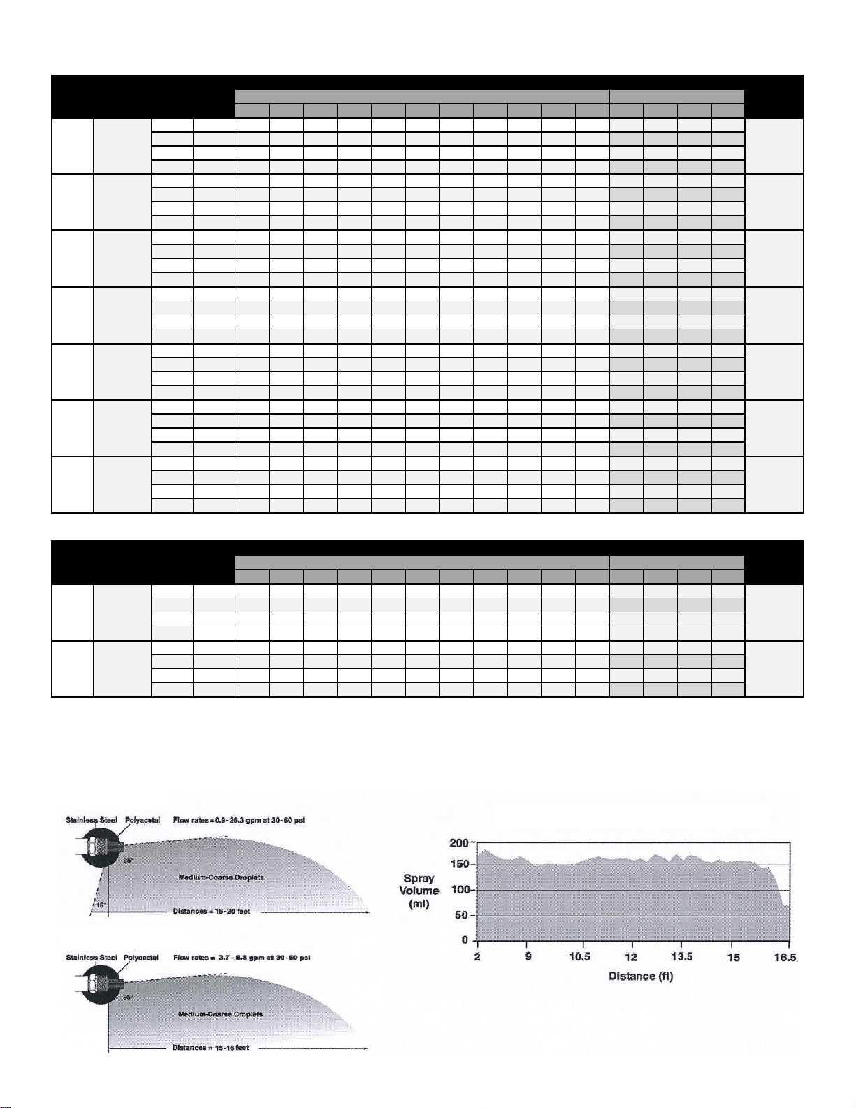
3/8"
MNPT
XT043R
BLUE
1/2"
MNPT
XT080R
YELLOW
Swath
Width (Ft)
@ 40 PSI
16
1718181716
20
Swath
Width (Ft)
@ 40 PSI
16
15
RIGHT-OF-WAY APPLICATIONS
Gallons per Acre
GAL/1000 Sq. Ft.
MPH
MPH
1/2"
MNPT
XT080
RED
3/4"
MNPT
XT167
WHITE
3/4"
MNPT
XT215
GRAY
1/4"
MNPT
XT020
FC-XT020
BLUE
1/4"
MNPT
XT024
FC-XT024
YELLOW
3/8"
MNPT
XT043
FC-XT043
ORANGE
BROADCAST & TURF APPLICATIONS
1/4"
MNPT
XT010
GREEN
Gallons per Acre
GAL/1000 Sq. Ft.
MPH
MPH
Boomless spray nozzles are great for rough terrains, road side spraying, fence rows and other areas that are difficult to apply with a traditional boom.
Note: Application rates are based on overall swath widths listed at 48” height. Refer to operating instructins if using a different swath.
Note: Application rates are based on overall swath widths listed at 48” height. Refer to operating instructins if using a different swath.
Standard Pattern
Typical Spray Pattern Produced by XT Series
Right-of-Way Pattern
Page 3
 Loading...