

Page 1

WORKSHOP HANDBOOK
MXR
Version: AA
Date: January 15, 2014
Document Number:10045983/ATE
Page 2

Contents
I Product Introduction 4
1 Serial Number and Technical Support 5
1.1 The Serial Tag . . . . . . . . . . . . . . . . . . . . . . . . . . . . . . . . . 5
1.2 Serial Tag location . . . . . . . . . . . . . . . . . . . . . . . . . . . . . . . 5
2 Main Technical Features 6
II Anomalies Resolution Guide 8
3 Trouble-shooting for the most common anomalies 9
3.1 Electrical system: what to do if. . . . . . . . . . . . . . . . . . . . . . . . . 9
3.2 Mechanical scrubbing system: what to do if. . . . . . . . . . . . . . . . . 12
3.3 Drying system: what to do if. . . . . . . . . . . . . . . . . . . . . . . . . . 13
3.4 Frame and traction system: what to do if. . . . . . . . . . . . . . . . . . . 15
3.5 Solution delivery system: what to do if. . . . . . . . . . . . . . . . . . . . 16
4 Disassembling Procedures 17
4.1 Electrical Installation . . . . . . . . . . . . . . . . . . . . . . . . . . . . . 18
4.2 Mechanical Friction System . . . . . . . . . . . . . . . . . . . . . . . . . 20
4.3 Drying System . . . . . . . . . . . . . . . . . . . . . . . . . . . . . . . . . 22
4.4 Frame and Traction System . . . . . . . . . . . . . . . . . . . . . . . . . 25
4.5 Solution Delivery System . . . . . . . . . . . . . . . . . . . . . . . . . . . 27
III Machine Description 30
5 Electrical System 31
5.1 Structure . . . . . . . . . . . . . . . . . . . . . . . . . . . . . . . . . . . . 31
5.2 Description . . . . . . . . . . . . . . . . . . . . . . . . . . . . . . . . . . . 31
5.3 Location of Electrical components . . . . . . . . . . . . . . . . . . . . . . 32
5.4 Adjustments . . . . . . . . . . . . . . . . . . . . . . . . . . . . . . . . . . 40
5.5 Maintenance and Checks . . . . . . . . . . . . . . . . . . . . . . . . . . . 43
5.6 Alarm Table . . . . . . . . . . . . . . . . . . . . . . . . . . . . . . . . . . . 44
5.7 Menu tables . . . . . . . . . . . . . . . . . . . . . . . . . . . . . . . . . . . 45
5.8 Technical Features . . . . . . . . . . . . . . . . . . . . . . . . . . . . . . . 51
5.9 Recommended Spare Parts . . . . . . . . . . . . . . . . . . . . . . . . . . 51
2
Page 3

6 Mechanical Rubbing System 52
6.1 Structure . . . . . . . . . . . . . . . . . . . . . . . . . . . . . . . . . . . . 52
6.2 Description: . . . . . . . . . . . . . . . . . . . . . . . . . . . . . . . . . . . 52
6.3 Adjustments . . . . . . . . . . . . . . . . . . . . . . . . . . . . . . . . . . 53
6.4 Maintenance and checks . . . . . . . . . . . . . . . . . . . . . . . . . . . 53
6.5 Technical Features . . . . . . . . . . . . . . . . . . . . . . . . . . . . . . . 56
6.6 Consumable Spare Parts . . . . . . . . . . . . . . . . . . . . . . . . . . . 56
6.7 Recommended Spare parts . . . . . . . . . . . . . . . . . . . . . . . . . . 56
7 Drying System 57
7.1 Structure . . . . . . . . . . . . . . . . . . . . . . . . . . . . . . . . . . . . 57
7.2 Description . . . . . . . . . . . . . . . . . . . . . . . . . . . . . . . . . . . 57
7.3 Adjustments . . . . . . . . . . . . . . . . . . . . . . . . . . . . . . . . . . 58
7.4 Maintenance and Checks . . . . . . . . . . . . . . . . . . . . . . . . . . . 59
7.5 Technical Features . . . . . . . . . . . . . . . . . . . . . . . . . . . . . . . 63
7.6 Consumable Spare Parts . . . . . . . . . . . . . . . . . . . . . . . . . . . 63
7.7 Recommended Spare Parts . . . . . . . . . . . . . . . . . . . . . . . . . . 63
8 Machine Frame and Traction System 64
8.1 Structure . . . . . . . . . . . . . . . . . . . . . . . . . . . . . . . . . . . . 64
8.2 Description . . . . . . . . . . . . . . . . . . . . . . . . . . . . . . . . . . . 64
8.3 Adjustments . . . . . . . . . . . . . . . . . . . . . . . . . . . . . . . . . . 65
8.4 Maintenance and Checks . . . . . . . . . . . . . . . . . . . . . . . . . . . 66
8.5 Technical Features . . . . . . . . . . . . . . . . . . . . . . . . . . . . . . . 68
8.6 Consumable spare parts . . . . . . . . . . . . . . . . . . . . . . . . . . . 68
8.7 Suggested spare parts . . . . . . . . . . . . . . . . . . . . . . . . . . . . . 68
9 Cleaning Solution Supply System 69
9.1 Structure . . . . . . . . . . . . . . . . . . . . . . . . . . . . . . . . . . . . 69
9.2 Description: . . . . . . . . . . . . . . . . . . . . . . . . . . . . . . . . . . . 69
9.3 Maintenance and Checks . . . . . . . . . . . . . . . . . . . . . . . . . . . 70
9.4 Technical Features . . . . . . . . . . . . . . . . . . . . . . . . . . . . . . . 72
9.5 Recommended Spare parts . . . . . . . . . . . . . . . . . . . . . . . . . . 72
IV Accessories and Add-On 73
10 Accessories 74
10.1Accessories List . . . . . . . . . . . . . . . . . . . . . . . . . . . . . . . . 74
10.2Blinking Kit - 222471 . . . . . . . . . . . . . . . . . . . . . . . . . . . . . 74
10.3Onboard Charger Kit - 222386 . . . . . . . . . . . . . . . . . . . . . . . . 76
10.4Splashguard Kit - 222480 . . . . . . . . . . . . . . . . . . . . . . . . . . 77
10.5Cleaning Accessories Kit - 222472 . . . . . . . . . . . . . . . . . . . . . 78
10.6Consumable Spare Parts . . . . . . . . . . . . . . . . . . . . . . . . . . . 80
Page 4

Part I
Product Introduction
4
Page 5

1-5
Chapter 1
Serial Number and Technical Support
1.1 The Serial Tag
1.2 Serial Tag location
To have access to the Serial Tag is necessary to open the glove box on the steering
column.
The Serial Number is an extremely important information which has to be provided
each time a Technical Support is required or is necessary to buy spare parts or
accessories. The serial number is the only way to identify the machine by model,
production date type equipments in general.
5
Page 6

2-6
Chapter 2
Main Technical Features
Technical Data
TECHNICAL DESCRIPTION U/M Mxr
Maximum Ramp Gradient % 8
Steering Diameter mm 3680
Machine Length mm 1265
Machine length with optional storage compartment mm 1400
Machine Height mm 1030
Machine height with optional blinking kit mm 1070
Machine Width (without squeegee) mm 600
Machine Width
(without squeegee) with optional toolbox kit
mm 620
Wheel Base mm 730
Wheel Track mm 520
Footrest height from the ground mm 230
Seat height from the footrest mm 466
Handlebar distance from the back seat mm 530
6
Page 7

2-7
Weigths and Pressures
1
TECHNICAL DESCRIPTION U/M Mxr
Machine Weight (empty and without batteries) kg 110.4
Gross Weight of the machine in work conditions
(machine + batteries + water + operator)
kg 332.4
Weight front wheel kg 80.00 ÷ 116.00
Front wheel touching surface cm
2
11.95 ÷ 14.14
Front wheel pressure
kg
cm
2
6.58 ÷ 8.21
Weight rear right wheel kg 84.03 ÷ 120.80
Rear right wheel touching surface cm
2
7.42 ÷ 10.28
Rear right wheel pressure
kg
cm
2
10.44 ÷ 11.75
Weight rear left wheel kg 85.50 ÷ 123.40
Rear left wheel touching surface cm
2
8.62 ÷ 10.35
Rear left wheel pressure
kg
cm
2
8.40 ÷ 12.87
1
Weight and Pressures depends on how much water there is in the tanks and on what type of battery the
machine fits.
Page 8

2-8
Part II
Anomalies Resolution Guide
8
Page 9

3-9
Chapter 3
Trouble-shooting for the most common
anomalies
3.1 Electrical system: what to do if. . .
The machine doesn’t switch on
1 The emergency button is pressed ⇒ Release the emergency button.
2 The key is in position 0 ⇒ Rotate the key in position I.
3 The key switch is not properly con-
nected
⇒ Restore the proper connections.
4 The key switch doesn’t work ⇒ Replace the key switch (see section 4.1.1
at page 18).
9
Page 10

3-10
The batteries don’t work properly
1 The batteries are not properly con-
nected
⇒ Restore the proper battery connec-
tions.
2 The batteries are discharged ⇒ Perform a complete charge cycle.
3 Battery terminal are oxidized ⇒ Disconnect the batteries, clean the
batteries terminals and reconnect
properly the batteries.
4 With the machine in working con-
ditions one battery has a voltage
lower (difference higher than 2 V)
than the other ones
⇒ Replace the battery with lower volt-
age.
5 The fuse on the loop wire is dam-
aged
⇒ Check for possible short circuits, If
not present replace the loop wire.
6 The power wires are damaged ⇒ Replace the damaged wires.
7 The battery charger is not properly
adjusted
⇒ Adjust properly the battery charger.
8 The battery charger doesn’t work ⇒ Check the proper section (see section 3.1
at page 10).
The battery charger doesn’t work
1 The battery charger is not con-
nected to the power supply
⇒ Connect the charger to a supplied
electric socket.
2 The battery charger is not con-
nected to the batteries
⇒ Connect the charger to the batteries.
3 The battery charger has one or
more lights (or LEDs) blinking continuously
⇒ The battery charger is in error con-
ditions, verify the alarm tables and
solve the issue by following the related instructions (see section 5.3.8 at page
40).
4 The battery charger is properly con-
nected but it doesn’t switch on
⇒ Replace the battery charger.
Page 11

3-11
The display shows an alarm message
1 The display shows an alarm mes-
sage
⇒ Check what alarm message is
shown and solve the related issue
by following the proper instructions
(see section 5.6.1 at page 44).
The machine has a very limited working autonomy
1 The batteries connections are oxi-
dized
⇒ Unplug the connection wires, wash
the wire connections with water and
reconnect them protecting them with
grease.
2 When the machine is working a bat-
tery voltage is lower and lower than
the other batteries (The difference is
bigger than 2V)
⇒ Replace the battery with the lower
voltage.
3 The battery charger is not properly
adjusted
⇒ Verify the type of battery in use and
adjust the battery charger properly
following the instructions (see section
5.4.3 at page 41).
4 The BDI (Battery Discharge Indica-
tor) is not properly adjusted
⇒ Verify the type of battery used on
the machine and adjust properly the
BDI.
5 Batteries have been working for
several cycles
⇒ Replace the batteries.
Page 12

3-12
3.2 Mechanical scrubbing system: what to do if. . .
The machine doesn’t clean well
1 The machine is switched off ⇒ Switch on the machine.
2 The machine doesn’t switch on ⇒ Refer to the proper section (see section
3.1 at page 9).
3 The machine is not in working con-
dition
⇒ Switch on the machine.
Lower the scrubbing base.
Press the traction pedal.
4 The display shows an alarm mes-
sage
⇒ Check what alarm message is
shown and solve the related issue
by following the proper instructions
(see section 5.6.1 at page 44).
5 The brush rotates in opposite way ⇒ Check the motor connections.
6 The brush deck motor is not sup-
plied
⇒ Verify the motor connections.
7 The microswitch of the scrubbing
base lifting lever doesn’t work
⇒ Replace the microswitch (see section 4.1.6
at page 19).
8 The microswitch of the traction
pedal doesn’t work
⇒ Replace the microswitch (see section 4.1.4
at page 19).
9 The brush is not properly engaged ⇒ Release and engage properly the
brush.
10) The solution flow rate is not correct
or not enough
⇒ Refer to the proper section.
The brush deck doesn’t move
1 The brush deck Lever doesn’t move ⇒ Check that there are no mechani-
cal obstacles to the movement of the
lever.
2 The lever moves but the brush deck
doesn’t move
⇒ Check that the lifting cable runs in
its sheath and the chain is free to
move. Check that the brush deck lifting arms are free to move.
3 The brush deck is lowered but it
doesn’t touch the ground
⇒ Check the settings of the lifting ca-
ble.
Page 13

3-13
3.3 Drying system: what to do if. . .
The machine doesn’t dry well
1 The machine is switched off ⇒ Switch on the machine.
2 The machine doesn’t switch on ⇒ Refer to the proper section (see section
3.1 at page 9).
3 The squeegee is lifted up from the
floor
⇒ Lower down the squeegee.
4 The squeegee rubber blades are
worn out or broken
⇒ Rotate or replace the squeegee rub-
ber blades.
5 The recovery tank is full ⇒ Empty the recovery tank following
the proper procedure.
6 The squeegee is not properly ad-
justed
⇒ Adjust the squeegee properly follow-
ing the proper procedure (see section 7.3.1
at page 58).
7 The squeegee vacuum chamber is
stuck or dirty
⇒ Clean the squeegee vacuum cham-
ber.
8 The squeegee adapter is stuck or
dirty
⇒ Clean the squeegee adapter.
9 The vacuum hose is stuck or bro-
ken
⇒ Clean or replace the vacuum hose.
10 The vacuum hose is not properly
fitted in
⇒ Connect the vacuum hose properly.
11 The vacuum filter is dirty or stuck ⇒ Disassemble and clean the vacuum
filter.
12 The vacuum cover is not well posi-
tioned or is missing
⇒ Position properly the vacuum cover.
13 The vacuum cover gasket doesn’t
adhere properly
⇒ Replace the vacuum cover gasket.
Page 14

3-14
The vacuum motor doesn’t work properly
1 The vacuum motor is switched off ⇒ Switch on the vacuum motor.
2 The vacuum motor is not powered
properly
⇒ Check the power connections on the
vacuum motor.
3 The microswitch on the squeegee
lifting lever doesn’t work
⇒ Replace the microswitch.
4 The display shows an alarm mes-
sage
⇒ Check what alarm message is
shown and solve the related issue
by following the proper instructions
(see section 5.6.1 at page 44).
5 The vacuum motor carbon brushes
are worn out
⇒ Replace the vacuum motor carbon
brushes.
6 The vacuum motor is supplied but
it doesn’t work
⇒ Replace the vacuum motor.
The squeegee doesn’t move
1 The squeegee Lever doesn’t move ⇒ Check that there are no mechani-
cal obstacles to the movement of the
lever.
2 The lever moves but the squeegee
doesn’t move
⇒ Check that the lifting cable runs in
its sheath and the chain and the
rear lever is free to move.
3 The squeegee is lowered but it
doesn’t touch the ground
⇒ Check the settings of the lifting ca-
ble.
Page 15

3-15
3.4 Frame and traction system: what to do if. . .
The traction motor doesn’t work properly
1 The machine is switched off ⇒ Switch on the machine.
2 The machine doesn’t switch on ⇒ Check the proper section (see section 3.1
at page 9).
3 The batteries are discharged ⇒ Connect the battery charger and
perform a complete charge cycle.
4 The operator is not sitting on the
seat
⇒ The operator must sit on the seat.
5 The operator is sitting on the seat ⇒ Check and / or replace the deadman
seat microswitch.
6 The pedal is not pressed ⇒ Press the pedal depending on the re-
quired speed.
7 The pedal is pressed ⇒ Check and / or replace the poten-
tiometer or the microswitch inside
the pedal.
8 The display shows an alarm mes-
sage
⇒ Check what alarm message is
shown and solve the related issue
by following the proper instructions
(see section 5.6.1 at page 44).
9 The brush deck motor is not sup-
plied
⇒ Verify the motor connections.
10 The electrobrake doesn’t disengage ⇒ Check the connections of the electro-
brake.
Page 16

3-16
3.5 Solution delivery system: what to do if. . .
The delivered solution is not correct or not enough
1 The machine is switched off ⇒ Switch on the machine.
2 The machine doesn’t switch on ⇒ Refer to the proper section (see section
3.1 at page 9).
3 The solution tank is empty ⇒ Fill up the solution tank.
4 The proportional valve for the solu-
tion flow adjustment is completely
closed
⇒ Open the proportional valve to the
desired position.
5 The hose that connects the solution
tank to the filter is stuck
⇒ Clean the hose.
6 The solution filter is stuck ⇒ Clean the solution filter.
7 The brush deck is not in working
conditions
⇒ Lower the brush deck to the floor
Press the traction pedal to start the
washing.
8 The solenoid valve doesn’t work ⇒ Check the solenoid valve connec-
tions and, if necessary, replace it (see
section 4.5.4 at page 28).
9 The display shows an alarm mes-
sage
⇒ Check what alarm message is
shown and solve the related issue
by following the proper instructions
(see section 5.6.1 at page 44).
10 The detergent doesn’t fit the type of
dirt
⇒ Replace the detergent with a proper
one.
Page 17

4-17
Chapter 4
Disassembling Procedures
WARNING : BE FORE TO PERF ORM ANY OPERA TION DES CRIBE D BE LOW VERIFY THAT
TH E MACHI NE TANK S A RE COMPLETEL Y E MPTY, TH E MACHI NE HAS TO BE TUR NED
OFF . DI SCONN ECT THE BA TTERIES AN D REM OVE THEM FROM THE MAC HINE . AT LAST,
VE RIFY TH AT THE PAR KING BRAKE IS ENGA GED AND TH E M ACHINE IS IN A T OTALL Y
SA FE COND ITIO N.
17
Page 18
4-18
4.1 Electrical Installation
4.1.1 Key Switch
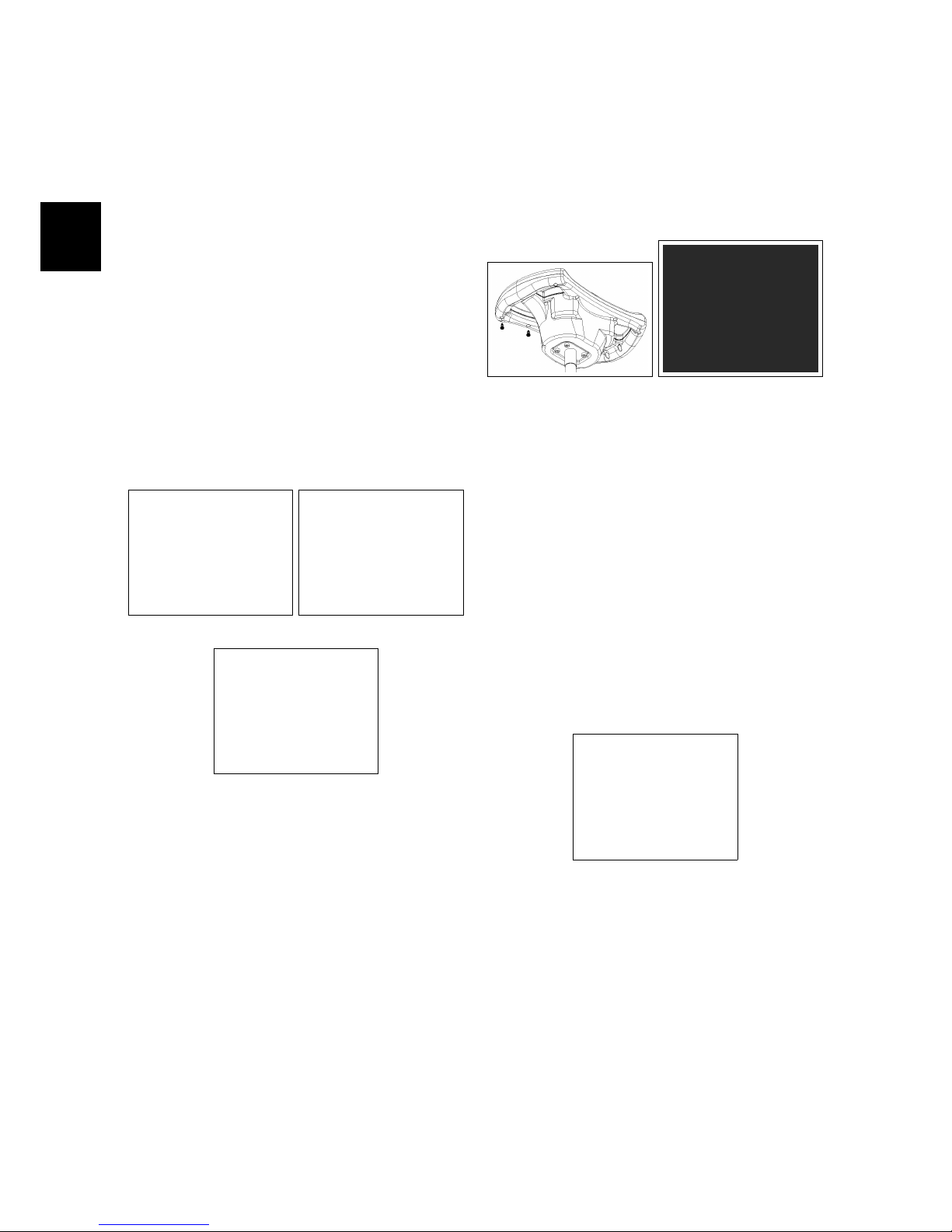
• Put the machine in safe conditions.
• Remove the screws that secure the
front carter to the steering column
(see fig. 4.1.1-1) (see fig. 4.1.1-2).
• Disconnect the wires connected to
the key switch.
• Unscrew the ring nut that secures
the key switch to the steering column (see fig. 4.1.1-3).
• Remove the key switch.
4.1.1-1 4.1.1-2
4.1.1-3
4.1.2 Control Card
• Put the machine in safe conditions.
• Remove the screws that secure the
upper and lower part of the steering
wheel (see fig. 4.1.2-4).
• Separate the top part from the bottom part.
• Disconnect the communication cable between the Control card and the
Main card.
• Unscrew the screws on the control
card from the top part and remove
the card (see fig. 4.1.2-5).
4.1.2-4 4.1.2-5
4.1.3 Main Card
• Put the machine in safe conditions.
• Remove the screws to remove the
footrest.
• Remove the screws to remove the
electrical system cover (see fig. 4.5.1-56).
4.1.3-6
• Disconnect the electrical wiring of
the emergency button and of the
Main card.
• Remove the screws that secure the
card to the support bracket.
• Remove the card.
Page 19
4-19
4.1.4 Traction Pedal
• Put the machine in safe conditions.
• Remove the screws to remove the
footrest.
• Release the footswitch connector
and unscrew the two screws holding
the pre-assembly pedal.
• Remove the pedal.
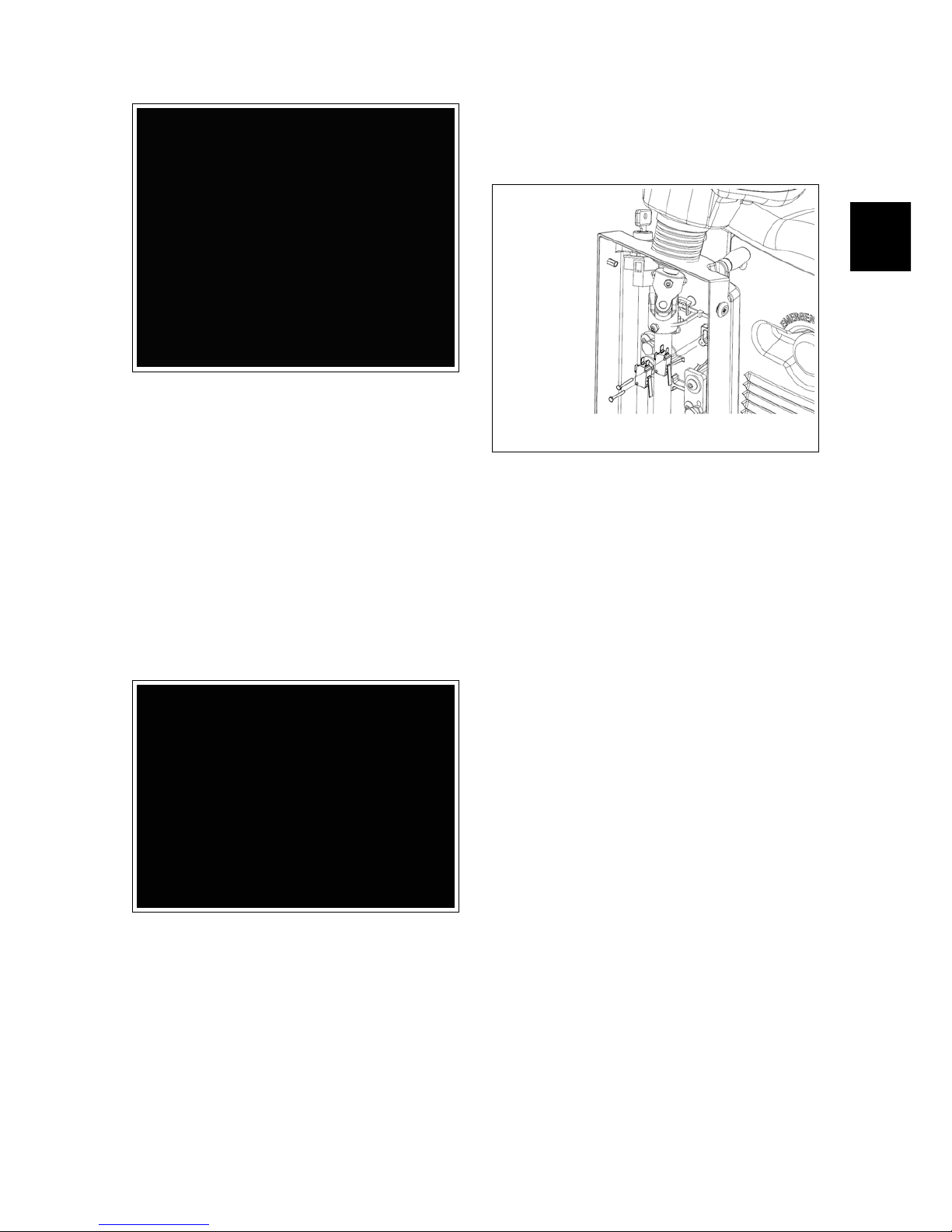
4.1.5 Microswitch
• Put the machine in safe conditions.
• Remove the screws that secure the
front carter to the steering column.
• Disconnect the wires connected to
the microswitch.
• To remove the microswitch, unscrew
the two screws and remove the device.
4.1.6 Dead Man Switch (Seat
microswitch)
• Put the machine in safe conditions.
• Unscrew the screws to remove the
electrical system cover (see fig. 4.5.1-56).
• Unscrew the lower screws that fix
the seat (see fig. 4.1.6-8).
• Unscrew the rear screws that fix the
seat (see fig. 4.1.6-9).
• Remove the seat from the machine
(see fig. 4.1.6-10).
• Remove the switch connecting
joints.
• Remove the dead man Switch.
Page 20

4-20
4.1.6-7 4.1.6-8
4.1.6-9 4.1.6-10
4.2 Mechanical Friction
System
4.2.1 Brush Deck Assembly
• Release the brush from the Brush
Deck.
• Put the machine in safe conditions.
• Make sure that the electrobrake is
enabled.
• Lower the brush deck to the floor.
• Remove the lift arms from the frame.
• Disconnect the electrical connector
of the brush motor and the electric
connector of the solenoid valve.
• Disconnect the solution supply
hose.
• Disconnect the lift chain from the
brush plate.
• Lift the front wheel in order to lift the
front part of the machine of about
20cm.
• Pull off the brush deck sideways to
the machine.
4.2.2 Brush Coupling Flange
• Put the machine in safe conditions.
• Disassemble the Brush Deck from
the machine (see section 4.2.1 at page 20).
• Unscrew the Coupling Flange rotating it in the same direction as the
brush in standard working conditions.
• Proceed at reverse to refit the part.
Note: Before to refit the part lubricate
the thread in order to prevent blockings
because of dirt or oxide.
4.2.2-11
4.2.3 Brush Motor
• Put the machine in safe conditions.
• Disassemble the Brush Deck from
the machine (see section 4.2.1 at page 20).
• Unscrew the Coupling Flange from
the motor shaft (see section 4.2.2 at page 20).
• Disconnect the electrical connector
of the motor.
• Disconnect the water hose from the
motor (see fig. 4.5.1-58).
• Unscrew the 4 fixing screws and remove the motor (see fig. 4.2.3-13).
• Proceed at reverse to refit the part.
Note: Use the thread lock liquid on the
screw during the assembling.
Page 21

4-21
4.2.3-12 4.2.3-13
4.2.4 Bumper Wheel
• Release the Brush from the Brush
deck.
• Put the machine in safe conditions.
• Make sure that the brush deck is in
lifted position.
• Unscrew the top bushing of the
wheel.
• Remove the wheel.
• Proceed at reverse to refit the part.
Note: Use the thread lock liquid on the
screw during the assembling.
4.2.5 Brush deck lifting arms
• Put the machine in safe conditions.
• Disassemble the Brush Deck from
the machine (see section 4.2.1 at page 20).
• Unscrew the screws that hold the lift
arms from the brush deck (see fig. 4.2.5-
14) (see fig. 4.2.5-15).
• Proceed at reverse to refit the part.
4.2.6 Brass Bushings
• Put the machine in safe conditions.
• Disassemble the brush deck lifting
arms.
4.2.5-14 4.2.5-15
• Replace worn out bushings with new
ones.
• Proceed at reverse to refit the part.
• Before fixing the lift arms, proceed to
lubricate the bushings with grease.
4.2.7 Fixing and adjustment
plate
• Put the machine in safe conditions.
• Disassemble the Brush Deck from
the machine (see section 4.2.1 at page 20).
• Disassemble the brush deck lifting
arms.
• Remove the screw that secures the
fixing and adjustment plate to the
brush deck.
• Proceed at reverse to refit the part.
4.2.7-16
Page 22
4-22
4.3 Drying System
4.3.1 Squeegee
• Put the machine in safe conditions.
• Unplug the Vacuum Hose (see fig. 4.3.3-
26).
• Loose the knobs that block the
Squeegee to the Squeegee Support
(see fig. 4.3.1-18).
• Move the squeegee sideways to release it from the squeegee support
(see fig. 4.3.1-19).
• Proceed at reverse to refit the part.
• Check the adjustment of the
squeegee support.
4.3.1-17 4.3.1-18
4.3.1-19
4.3.2 Squeegee Support
Squeegee Coupling
• Put the machine in safe conditions.
• Disassemble the Squeegee from the
Machine.
• Loosen the screw that secures the
squeegee coupling from the lower
side of the squeegee support fulcrum
and remove it (see fig. 4.3.2-20).
• Loosen the screw that secures the
gas spring from squeegee coupling
and remove it (see fig. 4.3.2-20).
• Loosen the screw that secures the
chain to the squeegee rear lifting
lever (see fig. 4.3.2-21).
• Remove the squeegee support.
• Proceed at reverse to refit the part.
4.3.2-20 4.3.2-21
Squeegee Support Fulcrum
• Put the machine in safe conditions.
• Disassemble the squeegee coupling.
• Remove the batteries from the ma-
chine.
• Make sure that both tanks are completely empty.
• Remove the battery support from the
machine (see fig. 4.5.1-54)
• Loosen the upper fixing screw of the
squeegee support hub fulcrum (see fig.
4.3.2-23).
• Lay the machine on the left side.
Page 23
4-23
• Remove the screws that secure the
reinforcing plate of the squeegee
support fulcrum and remove it. together with, it will be also removed
the squeegee support fulcrum hub
(see fig. 4.3.2-24).
• Remove the squeegee support fulcrum rotating it properly (see fig. 4.3.2-
25).
4.3.2-22 4.3.2-23
4.3.2-24 4.3.2-25
4.3.3 Vacuum Hose
• Put the machine in safe conditions.
• Unplug the Vacuum Hose from the
Squeegee (see fig. 4.3.3-26).
• Uncouple the squeegee from the
plastic clip (see fig. 4.3.3-27).
• Uncouple the Vacuum Hose from the
Recovery tank Inlet (see fig. 4.3.3-28).
• Slip off the hose from its housing (see
fig. 4.3.3-29).
• Proceed at reverse to refit the part.
4.3.3-26 4.3.3-27
4.3.3-28 4.3.3-29
4.3.4 Recovery Tank
• Make sure that the recovery tank is
completely empty.
• Put the machine in safe conditions.
• Remove the recovery tank lid.
• Remove the vacuum hose (see fig. 4.3.4-
30).
• Unplug the charger cable - vacuum
motor - blinking light.
• Cut the clamps that secure the cables to the solution tank.
• Loosen the screw that fix the safety
cord of the tank (see fig. 4.3.4-31).
• Unscrew the screws holding the
opening hinges to the recovery tank
(see fig. 4.5.1-53).
• Proceed at reverse to refit the part.
Page 24
4-24
4.3.4-30 4.3.4-31
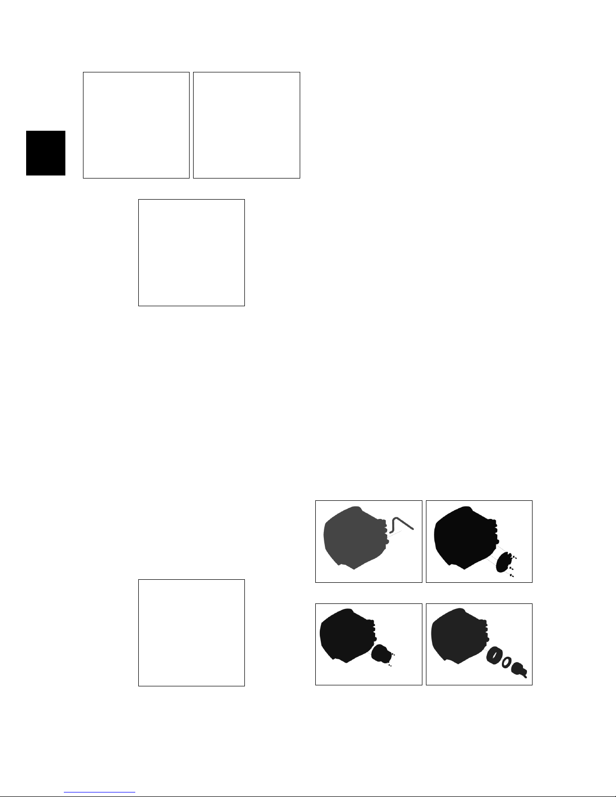
4.3.4-32
4.3.5 Floater and Vacuum Filter
• Put the machine in safe conditions.
• Remove the Recovery Tank Lid.
• Unscrew the floating filter body.
• Remove the cap from the floating fil-
ter body.
• Remove the sponge suction filter.
• Proceed at reverse to refit the part.
4.3.5-33
4.3.6 Vacuum Motor
• Put the machine in safe conditions.
• Open the Recovery Tank.
• Disconnect the power cords of the
Vacuum Motor.
• Cut the plastic clamp that secures
the condensate drain hose to the recovery tank (see fig. 4.3.6-34).
• Loosen the screws and remove the
vacuum motor cover (see fig. 4.3.6-35).
• Unscrew the nuts that secure the
vacuum motor to the recovery tank
(see fig. 4.3.6-36).
• Pull out the vacuum motor and remove the sound absorbing sponges
(see fig. 4.3.6-37).
• Loosen the screws to remove the motor fixing plate.
• Proceed at reverse to refit the part.
4.3.6-34 4.3.6-35
4.3.6-36 4.3.6-37
Page 25
4-25
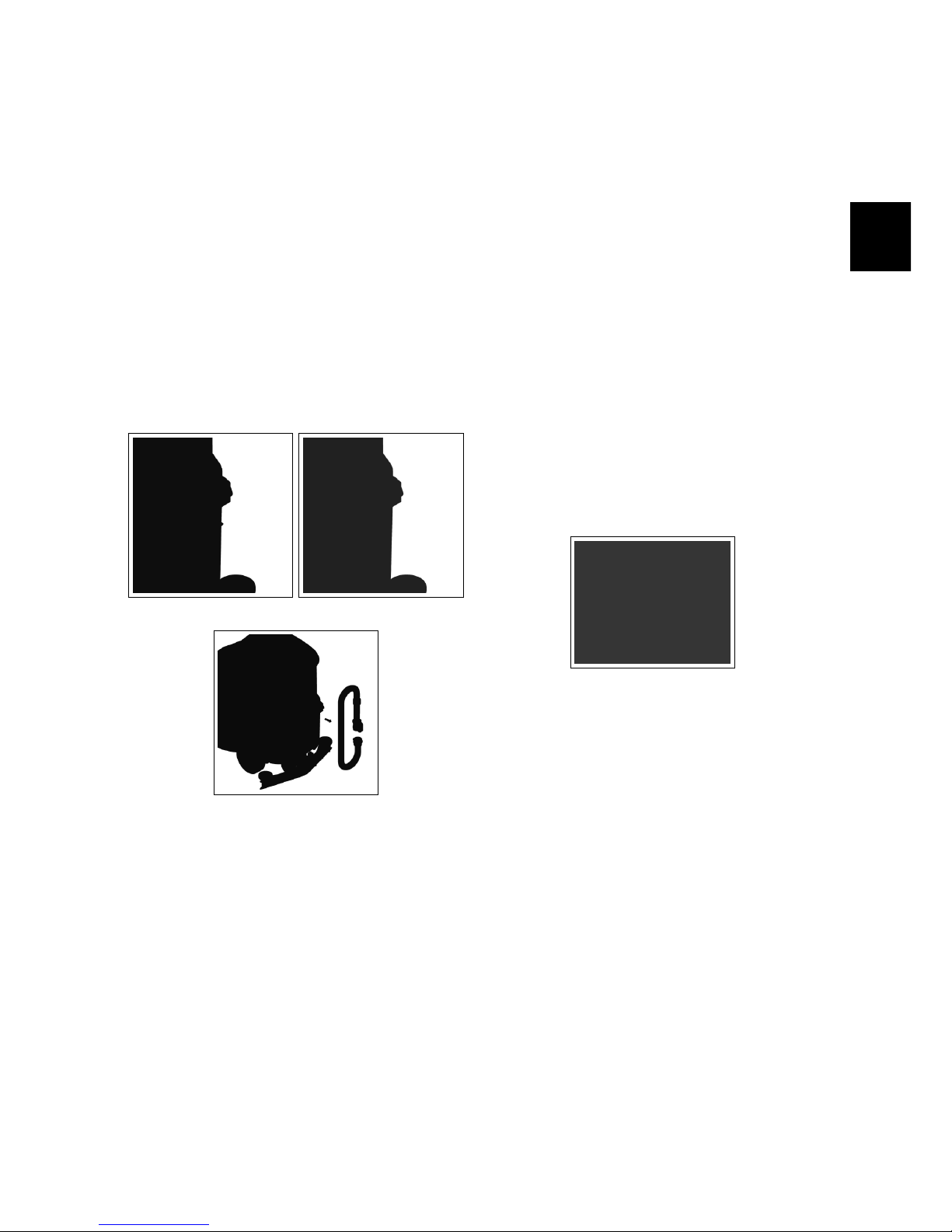
4.3.7 Drain Hose
• Put the machine in safe conditions.
• Loosen the clamp that secures the
drain hose to the recovery tank (see fig.
4.3.7-38).
• Unhook the hose from the plastic
clip (see fig. 4.3.7-39).
• Remove the hose from its housing (see
fig. 4.3.7-40).
• Proceed at reverse to refit the part.
4.3.7-38 Fase 1 4.3.7-39 Fase 2
4.3.7-40 Fase 3
4.4 Frame and Traction
System
4.4.1 Front Wheel
• Put the machine in safe conditions.
• Lift up the front wheel from the
ground.
• Unscrew one of the fixing screws of
the wheel shaft to the support.
• Remove the wheel securing shaft to
the support.
• Proceed at reverse to refit the part.
4.4.1-41
4.4.2 Rear Wheel
• Put the machine in safe conditions.
• Lift up the related rear wheel from
the ground.
• Remove the hub cap by levering with
a small flat screwdriver.
• Loosen the fixing bolt of the wheel to
the axle shaft.
• Proceed at reverse to refit the wheel
(Use the thread lock liquid on the
screw during the assembling).
Page 26

4-26
4.4.2-42 Regolazione
sterzo
4.4.3 Steering shaft
• Put the machine in safe conditions.
• Remove the front carter from the
steering column by loosening the
screws.
• Loosen the upper grains from the
universal joint.
• Remove the steering wheel from the
machine.
• Loosen the lower grains from the
universal joint.
• Loosen the chain draw grains.
• Remove the chain joint.
• Remove the chain from the steering
column.
• Remove the column support by loosening the screws.
• Remove the chain tensioner bracket.
• Pull out the steering column from
the lower support.
• Proceed at reverse to refit the part.
4.4.4 Steering Chain
• Put the machine in safe conditions.
• Remove the front carter from the
steering column by loosening the
screws (see fig. 4.5.1-55).
• Loosen the screws that secure the
lower support of the steering shaft
(see fig. 4.4.4-44).
• Loosen the grains (see fig. 4.4.4-45).
• Remove the chain joint (see fig. 4.4.4-47).
• Remove the chain from the sprocket.
• Proceed at reverse to refit the part.
4.4.4-43 4.4.4-44
4.4.4-45 4.4.4-46
4.4.4-47
4.4.5 Crown of the wheel support bearings cam
• Put the machine in safe conditions.
• Remove the steering chain (see section
4.4.4 at page 26).
• Lift the front wheel off the ground.
• Remove the screws securing the
front wheel to the frame (see fig. 4.4.5-
48).
Page 27

4-27
• Remove the sprocket fixing screws
(see fig. 4.4.5-49).
• Remove the sprocket.
• Remove the screws that secure the
cam to the sprocket and remove the
cam.
• Remove the Front Wheel (see fig. 4.4.5-
50).
• Remove the bearings pin.
• Remove the bearings (see fig. 4.4.5-52).
• Proceed at reverse to refit the part.
ATTE NTIO N: WHEN ASSEMBLI NG, PAY
EX TREM E ATTE NTION AT THE CORRECT
PO SITI ONING OF THE S PACE R 436224,
BE CAUS E I T IS FUND AMENTAL F OR THE
PR OPER FUNCTION ING OF THE PAR T.
4.4.5-48 Fixing screws of
the wheel to the frame
4.4.5-49 Fixing screws of
the steering sprocket
4.4.5-50 Wheel support
pin
4.4.5-51 Bearings in the
wheel fork
4.4.5-52 Bearings on the
steering sprocket
4.5 Solution Delivery Sys-
tem
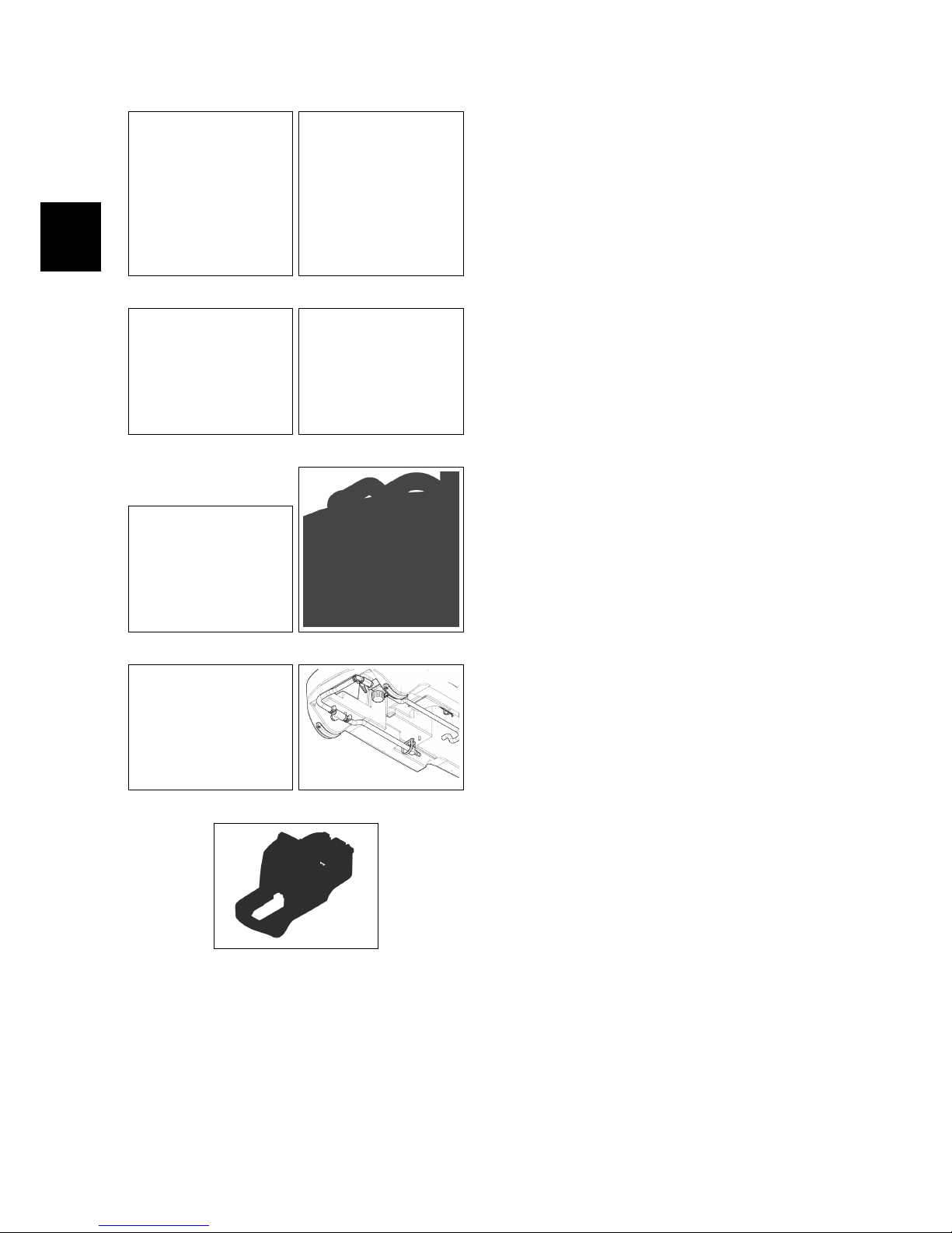
4.5.1 Solution Tank
• Put the machine in safe conditions.
• Remove the recovery tank (see section
4.3.4 at page 23) (see fig. 4.5.1-53).
• Remove the battery tray (see fig. 4.5.1-54).
• Remove the steering column
carter.(see fig. 4.5.1-55).
• Remove the footrest.
• Remove the electrical installation
carter (see fig. 4.5.1-56).
• Remove the support bracket of the
Main card.
• Remove the traction pedal assembly.
• Remove the seat and the deadman
microswitch (see fig. 4.5.1-57).
• Disconnect the water hose from the
brush deck (see fig. 4.5.1-58).
• Disconnect the control rod from the
water valve (see fig. 4.5.3-62).
• Remove the screws that secure the
solution tank to the machine frame.
• Remove the tank, pulling it out from
the steering column, taking care not
to damage the steering wheel.
• Turn the tank and remove the solution delivery system (see fig. 4.5.1-60).
• Proceed at reverse to refit the part.
4.5.2 Hoses
• Put the machine in safe conditions.
• Loosen the clamps that hold the
hose to the fitting.
Page 28
4-28
4.5.1-53 4.5.1-54
4.5.1-55 4.5.1-56
4.5.1-57 4.5.1-58
4.5.1-59 4.5.1-60
4.5.1-61
• Cut any eventual clamps that secure
the hose to the machine body.
• Remove the hose from the fitting.
4.5.3 Water Valve/Solution Filter
• Put the machine in safe conditions.
• Disconnect the control rod from the
water valve (see fig. 4.5.3-62).
• Disconnect the hose from the fitting,
attached to the water valve (see fig. 4.5.3-
63).
• Disconnect the hose from the fitting
attached to the solution filter (see fig.
4.5.3-63).
• Loosen the screws that hold the support plate to the solution tank (see fig.
4.5.3-64).
• Remove the group including the water valve and the solution filter (see fig.
4.5.3-65).
• Unscrew the elbow fitting attached
to the water valve (see fig. 4.5.3-66).
• Unscrew the water valve from the
nipple fitting and remove it (see fig. 4.5.3-
67).
• Unscrew the nipple fitting from
the solution filter and unscrew the
straight fitting from the solution filter (see fig. 4.5.3-68).
• Remove the solution filter (see fig. 4.5.3-
68).
4.5.4 Solenoid Valve
• Put the machine in safe conditions.
• Remove the hoses connected to the
solenoid valve.
• Loosen the screw that secures the
solenoid connector and disconnect
the connector from the solenoid coil.
• Unscrew the plastic nut that secures
the solenoid valve to its support.
Page 29

4-29
4.5.3-62 4.5.3-63
4.5.3-64 4.5.3-65
4.5.3-66 4.5.3-67
4.5.3-68
Page 30

4-30
Part III
Machine Description
30
Page 31

5-31
Chapter 5
Electrical System
5.1 Structure
1. Main Card
2. Dash board
3. Control Card
4. Microswitches: brush motor, vacuum motor, inhibition of reverse,
curve speed reduction and deadman
switch
5. Electrobrake
6. Emergency button
7. Traction pedal
8. Batteries and battery charger
5.2 Description
A main card runs all the functions of the
machine, traction, brush base, vacuum
and water. The main card receive as input, all the information from the control
card, the safety micro and all the electronic devices of the machine. These signals are translated from the main card
to run correctly the scrubber dryer and
to prevent any safety problem to the operator. The dash board can be used
also as a programmer console to modify the parameter of all the machine’s
functions (traction, vacuum and washing) and, also, to check the consumption
of all the motors and batteries.
31
Page 32

5-32
5.3 Location of Electrical components
Page 33

5-33
List of Components
CB Battery charger
1
CBR Charger safety contact
CD Control Card
EL Solenoid Valve
FE Emergency button
J Main Card
LAMP Safety blinking light
M1 Traction Motor
M1E Traction Motor electrobrake
M2 Brush Motor
M3 Vacuum Motor
ML Control microswitches
MS Seat microswitch
MULTIM Curve sensor microswitch
PM Potentiometer and pedal microswitch
1
Optional
Page 34
5-34
5.3.1 Main Card
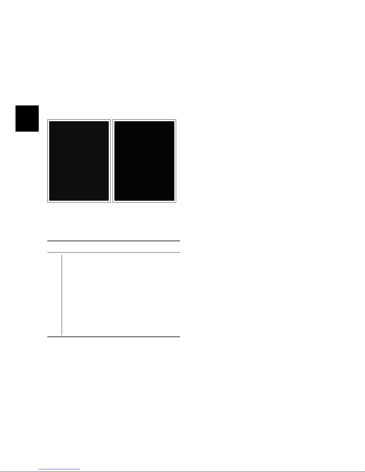
The Main Card is the heart of the machine and, depending of the input information, decides how to use the devices
of the machine during normal work. On
the table here below, is possible to identify the input/output signals of the card.
5.3.1-69 5.3.1-70
Input & Output Signals
F1 Key general fuse (3A).
J1 Vacuum motor and Brush motor.
J2 Traction motor.
J3 Solenoid valve, electrobrake, blinking
light.
J6 Dashboard control buttons.
J7 Limit switch: squeegee, brush deck,
curve speed reduction, inhibition of re-
verse, deadman switch, traction con-
trol, battery charger, potentiometer.
5.3.2 Dashboard and Control
card
Functions of Dashboard:
• Manage and set up the main functions and command of the machine
during the normal work.
• Check the alarm code in order to detect a possible malfunction.
• Enter in three different menu:
– The “user menu” to check the
status of the batteries and the
hourmeter of the machine (depending of the set up into “user
menu”). If a defect is detected
on the machine, this menu
show a short message concerning the alarm.
– The “operator menu” contain-
ing the basic adjustment, accessible by the user of the machine.
– The “advanced menu” where is
possible to modify the set up of
the machine by expert technicians.
ATTE NTIO N: THE “OP E RATOR MEN U”
IS AC CESS IBLE WIT HOUT ANY RE STRI C-
TI ON, WHE REAS TO ENTE R I NTO THE “A D -
VANCED MENU ” A P ASSWORD IS NEE DED.
Page 35
5-35
Functions and Commands
During the normal working, the display
shows the hourmeter and the battery
control card (in percentage). When the
charge of the batteries goes down to a
fixed value, the battery control card disable the brush motor and, after that, the
vacuum motor; in particular, the battery
control card disable the brush motor
(vacuum motor and traction motor still
work) when the remaining charge of the
batteries are 20% and disable also the
vacuum motor when the remains charge
of the batteries are 10%.
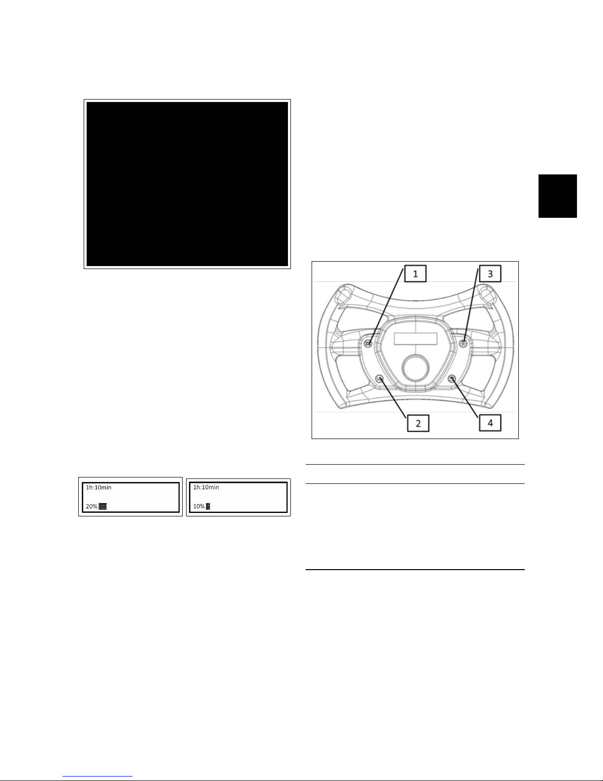
5.3.2-71 5.3.2-72
Entry into “Operator Menu” and “Advanced Menu”
The dashboard could be used like a programming console. If you press a determinate combination of buttons you can
enter into two menu:
• “Operator Menu”.
• “Advanced Menu”.
The structure of the menu can be shown
in the section (see section 5.7.1 at page 45):
Function of the buttons
1 Not Used
2 ENTER (Confirm)
3 SCROLL UP/PLUS (Scroll up and In-
crease)
4 SCROLL DOWN/MINUS (Scroll down
and Decrease)
Page 36

5-36
Operator Menu
To enter to the Operator menu go ahead
as follow:
• With the machine off, press in the
same time button “2”, “3” and “4”
• Turn on the key, with the three buttons pressed.
• Waiting the upload of the “working
menu”
• Release the buttons
To move inside of the menu, press the
button “3” and the button “4”.
To modify a parameter or confirm a
changed value, press the button “2”.
Change a Parameter (in the Operator
Menu)
To change a parameter proceed as follows:
• Run the menu with the button “3”
or “4” and select the parameter to
change.
• Select the submenu to be changed
pressing the button “2”
• Utilize the button “3” and “4”, to shift
all the available values for the parameter necessary to modify.
• To confirm the new value press the
button “2”
• To save the change is necessary to
return to the user menu; to exit from
“working menu” select the menu
“exit”
For example, to modify the language
from EN to IT
• Turn OFF the machine
• Press in the same time, the buttons
“2”, “3” and “4”
• Until the buttons are pressed, turn
ON the key and wait the upload of
the “working menu”
• Use the buttons “3” or “4” to select
the submenu “language”
• To modify the parameters of this
menu, press the button “2”. To confirm the possibility to change parameters, the first line on the display will
blink
• Utilize buttons “3” or “4” to shift all
the values on this menu and select
the value “IT”
• Confirm the new value by pressing
the button “2”
• To save this modification, select
the submenu “exit” and confirm by
pressing button “2”.
Page 37

5-37
Advanced Menu
The Advanced Menu can be reached
from the “operator menu” by accessing
the “password” parameter and setting
the value 60.
Change a Parameter (in the Advanced
Menu)
To change the value of a parameter, proceed as follows:
• Scroll through the submenus with
the buttons “3” and “4”.
• Select the submenu that contains
the parameters to be changed using
the button “2”.
• Scroll through the parameters with
the buttons “3” and “4” to find the
parameter to be edited.
• Select the parameter with the button
“2”.
• Use the buttons “3” and “4” to scroll
through the list of available values of
the parameter.
• Confirm the new value of the parameter using the button “2”.
• To enable the changes, it is necessary to return to the “menu work”;
to exit the parameters and return to
the “Advanced Menu” press simultaneously the buttons “3” and “4”,
then find the sub-menu “Exit” and
confirm with button “2”.
Check/Monitor Function
It is possible to view all the values of the
Check/monitor function during the normal work of the machine. To view the
values, following the instruction:
• Turn OFF the machine
• Press in the same time, the buttons
“2”, “3” and “4”
• Until the buttons are pressed, turn
ON the key and wait the upload of
the “working menu”
• Use the buttons “3” or “4” to select
the submenu “password”
• Confirm pressing button “2”
• Press button “3” or “4” until to select
the password “60”
• Confirm the password by pressing
the button “2” to enter into the “advanced menu”
• Press the button “3” or “4” to select
the menu “Check/Monitor”
• Confirm by pressing the button “2”
• Press the button “3” or “4” to se-
lect the parameter you want to check
during normal work.
• Press the button “2” to confirm
• After confirmed, the display will re-
turn to normal view, but instead of
the battery control card it will be displayed the values of the selected parameters.
• By pressing the button “2” it is possible to check the parameters of the
Check/Monitor submenu
• To exit form the “Check/Monitor”
view, turn OFF and ON the machine.
Page 38

5-38
5.3.3 Control Card
The Control Card is located inside of the
steering wheel and transfers all the information and settings to the Main Card.
The Control Card is linked to the Main
Card by a connecting cable (item J6).
5.3.4 Microswitches
The machine is provided with a series of
microswitches that send signals to the
main card. In particular:
• Brush motor Microswitch (1). With
lowered brush deck lifting lever and
closed micro the deck goes down to
the floor and the brush motor starts
running (as long as the gear pedal
is pressed). The cleaning function is
active.
• Vacuum motor Microswitch (2). With
lowered squeegee lifting lever and
closed micro the squeegee goes down
to the floor and the vacuum motor
starts running. The cleaning function is active.
• Reverse function Microswitch (3).
With lowered squeegee lifting lever
and activated drying function (closed
microswitch) the reverse function is
inhibited.
Page 39

5-39
• Curve speed reduction Microswitch.
it is positioned below the platform,
tangent to a cam. After a predetermined angle of rotation of the
steering, the microswitch opens and
the curve speed reduction function
is activated. The percentage of the
speed reduction is an adjustable parameter.
• Deadman Microswitch. The micro
switch is located below the seat.
With the operator on board, the traction and the brush deck can be activated.
5.3.5 Electrobrake
The machine is equipped with electrobrake. The electro-brake is engageable
through an appropriate control lever positioned on the electro-brake itself, close
to the traction motor. looking at a global
security condition, even if the machine is
switched off and the electrobrake is disengaged, the electrobrake blocks however, in case of exceeding a certain speed
(when pushing the machine or if the machine is on an inclined floor). If the machine is switched on, the drive is inhibited if the electrobrake is disengaged.
5.3.6 Emergency button
The machine is equipped with an emergency button, aimed at the protection
of the operator in case of sudden critical conditions. A press of the button
switches off the power to the Main card
and the machine stops immediately.
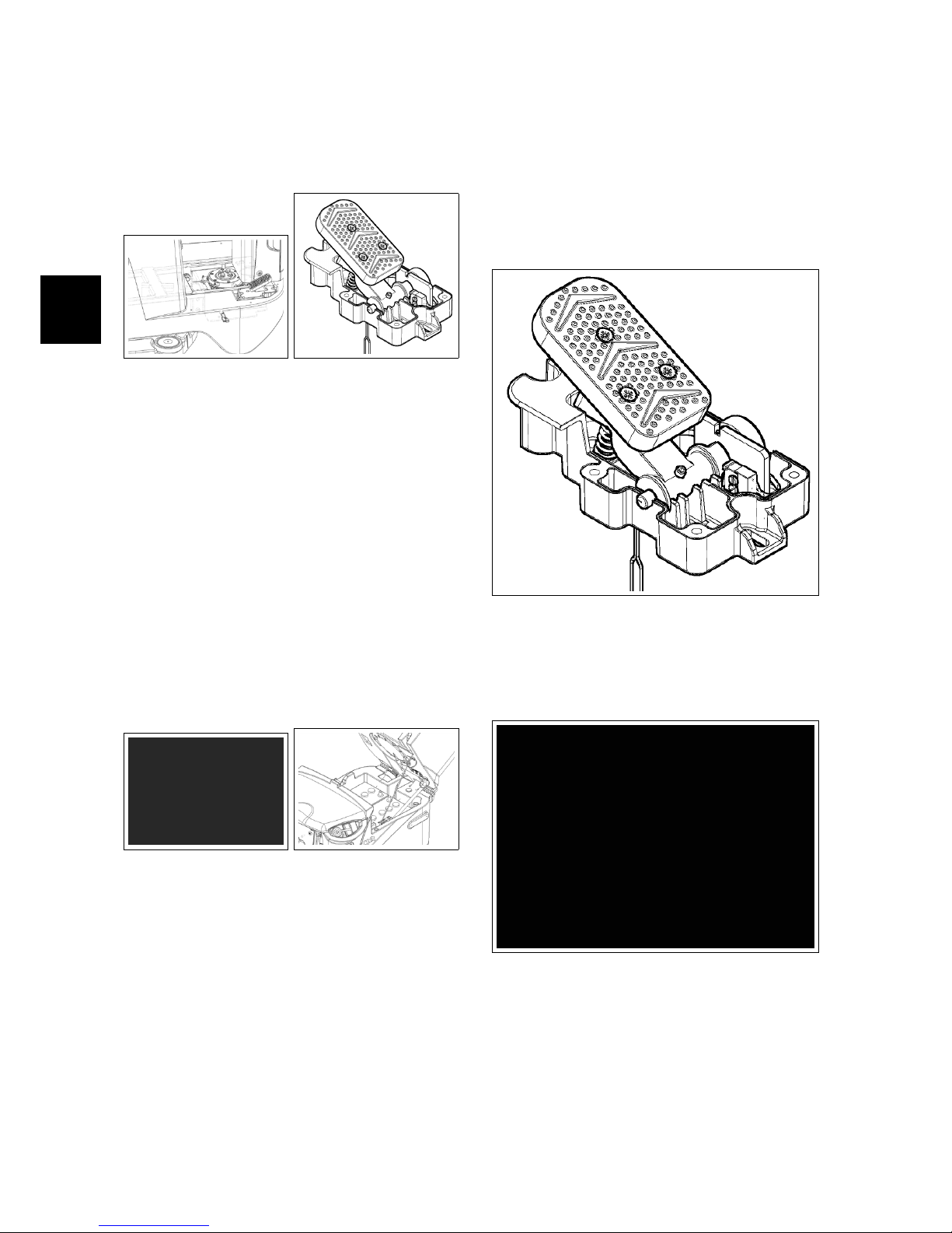
5.3.7 Traction Pedal
The traction pedal have an internal microswitch that closes when the pedal is
Page 40
5-40
pressed and a potentiometer to adjust
the intensity of the traction speed.
5.3.7-73 5.3.7-74
5.3.8 Batteries and battery
charger
The machine is available with the optional battery charger. To get access to
the battery charger and the battery compartment is enough to actuate the recovery tank release hook, positioned behind
the seat. On the batteries there is a loop
wire with 80 Ampere general protection
fuse.
5.3.8-75 5.3.8-76
5.4 Adjustments
5.4.1 Traction Pedal
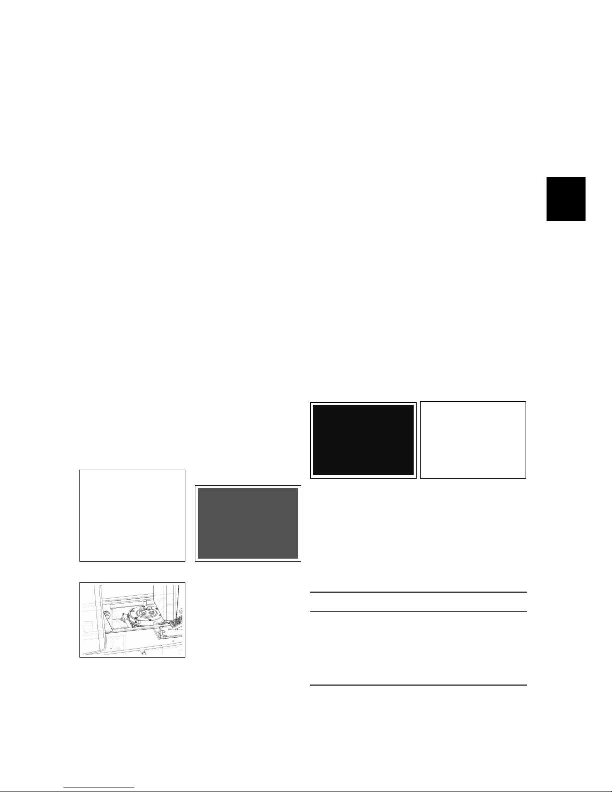
The microswitch and the potentiometer
inside the traction pedal are properly adjusted during assembly of the pedal.
If it is necessary to calibrate the potentiometer remove the platform, release
the control connector and pull the pedal
out by unscrewing the two screws.
Procedure:
• Remove the plastic cap and loosen
the adjustment dowel.
• Rotate the pedal lateral spindle
clockwise, until it is in the zero position.
Page 41
5-41
• Using the tester to measure the re-
sistance (Ω) place the tester terminals corresponding to the green and
yellow wires and check the resistance value to be approximately zero
Ω.
• Turn the potentiometer shaft counterclockwise until the tester gives
0,5 Ω (± 0,1).
• Lock the dowel and replace the plastic cap.
• Reinstall the pedal and the footrest.
5.4.2 Microswitch
Check functionality and conditions of
the brush motor microswitch, the vacuum motor microswitch, of reverse inhibition microswitch, the curve speed reduction microswitch. Check that with
microswitch pressed, remain about 0.5
mm clearance between the lever and the
body of the device. Make sure the lever
of the micro is working properly. Otherwise, proceed as follows:
5.4.2-77 5.4.2-78
5.4.2-79
• Unscrew the fixing screws.
• Move the DIP switches using the
loop adjustment.
• Fix the screws to lock the mi-
croswitches taking care not to over
tighten in order not to ruin the devices.
• When the setting is finished, verify
the correct functionality of the microswitches.
5.4.3 Battery Charger (CB)
The battery charger is positioned behind
the operator’s seat and is easily accessible by pressing the release button on the
recovery tank. When connected to the
power supply, a red led will blink once,
the yellow led blink once and the green
led blink depending of the type of battery
for which the charger is set.
5.4.3-80 5.4.3-81
A Proper Charging cycle follows the below phases order.
Phase LED Description
A Red Blinking, check of battery
status
B Red First charging phase
C YellowSecond charging phase
D Green Charged battery
Check if the charger is properly set according to the installed batteries.
Page 42
5-42
Charging curve SetUp
To set up the charger, follow the instructions:
• Use a screwdriver to remove the
small black plastic cap
• Set-up the internal dipswitches according to the following table
The dipswitches are divided in two couple. The higher couple are the dipswitches 1 and 2, the couple down are
the dipswitches 3 and 4. The following table shows how to setup the dipswitches 1 and 2.
Set-up of Charging Curve
DP1 DP2 Set Up Flash
OFF OFF Wet cell batteries 1
ON ON Gel TROJAN 2
OFF ON Generic GEL or
AGM batteries
3
ON OFF Gel EXIDE SON-
NENSCHEIN
4
DP3: OFF (not used)
DP4: OFF (not used)
Restore the the small black plastic cap.
Error Codes of Charger
The charger have an alarm system. The
alarm code is shown by blinks of the yellow led.
Error code
Flash Description
1 Wrong battery, Inverted polarity,
short circuit to the exit
2 Timeout alarm, Defect of the bat-
tery
3 Defect of the Charger
4 Overtemperature alarm
5.4.4 ECO Function
Once activated the ECO function (with
the proper button), lower the brushdeck
and let the brush motor and the vacuum
motor work. With the ECO mode activated, check if the noise of the vacuum
motor and the brush motor is reduced.
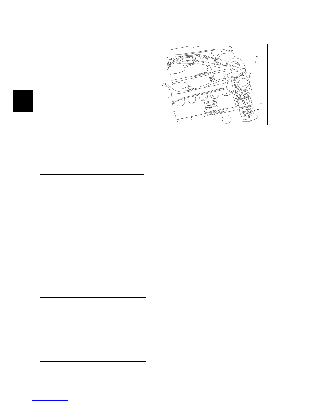
Connect an Amperometric to the positive
cable of the batteries and check if the
current consumption in ECO mode is
less than normal function (without ECO
mode). ATTENTION. We don’t give the
amperometric reference values because
they can change depending of the working conditions of the machine.
Page 43

5-43
5.5 Maintenance and
Checks
5.5.1 Electrical System
Check (to perform every 150h)
Check the functions and the proper connections of the switches, microswitches,
motors, solenoid valve, contactors,
power fuses, thermal fuses, battery loop
wires and emergency button. Check
periodically, the wiring connections
status. To get access to the electrical
system, remove the carter sited near the
emergency button.
5.5.2 Emergency Button
Check (to perform every 150h)
Check the correct functionality of the
emergency button. Once pressed, the
machine must stop immediately.
5.5.3 Electrobrake
Check (to perform every 150h)
Check the functionality of the electrobrake. With control lever rotated
downward (electrobrake ON), and
switched on machine, if the emergency
button is pressed, the machine must
stop immediately. With control lever
rotates upward (electrobrake OFF), and
switched on machine, the traction must
be disabled.
5.5.4 Batteries
Check (to perform every 150h)
Check the proper connection of the Loop
wire with 80 Ampere general fuse.
Page 44
5-44
5.6 Alarm Table
5.6.1 Alarms
Alarms of Overcurrent and Temperature
Id Alarm Meaning Solution
AL 1: Function
Amp. Brush
Brush Amperometric Protection Check consumption of the brush motor. Detected high current
on brush motor.
AL 2: Function
Amp. Vacuum
Vacuum Amperometric Protection
Check consumption of the vacuum motor. Detected high current on vacuum motor.
AL 3: Function
Power Broken
Damage of Power Damage power of brush or vacuum: replace the main card.
This alarm could be shown also during the trailing of the machine.
AL 4: Function
Overcurrent
Output overcurrent on brush or
vacuum
Detect a shortcircuit on output brush motor or vacuum motor:
Check connections and motors.
AL 5: Function
Overtemperature
Thermal protection on
brush/vacuum
Overtemperature of brush/vacuum motor: check consumption of motors.
Traction Alarms
Id Alarm Meaning Solution
AL 14: Traction
Lever pressed
Safety lever pressed before starting
Detected safety microswitch pressed before starting : release
the safety lever.
AL 15: Traction
Overtemperature
Thermal protection on traction Overtemperature on traction : check consumption of traction
motor (IMx BT).
AL 16: Traction
Power damage
Power of traction damage Replace the main card. This alarm could be shown also during
the trailing of the machine. (IMx BT)
AL 17: Traction
Overcurrent
Traction Overcurrent Detected a shortcircuit on the traction motor output: Check
connections and traction motor (IMx BT).
AL 18: Traction
Amp. Traction
Traction Amperometric protection
Check how the traction function is used. Detected too high
working current on traction motor (IMx BT).
AL 19: Traction
Electrobrake
Electrobrake not inserted Check the condition of the electrobrake and its related mi-
croswitch.
General Alarms
Id Alarm Meaning Solution
AL 20: General
EEprom malfunction
Error reading internal memory Replace the main card.
AL 21: General
Key
Error key sequence Error on key signal: Check the key connection. Check, also,
the batteries connections and main card
AL 22: General
General Relay
Damage of general relay Check the traction motor connections. If the connection are
OK, the general relay on the main card is damaged: replace
the main card. The same alarm is present also if power fuse is
damaged
AL 23: General
Overvoltage
Overvoltage Detected a overvoltage on the main card. Check the batteries
connections.
AL 24: Traction
Battery connections
Battery not connected to the
main card
Check the traction motor, Detected high voltage on traction
motor (IMx BT)
AL 25: General
Control Card connection
No communication between control card and main card
Check the connections between control card and main card.
Page 45
5-45
5.7 Menu tables
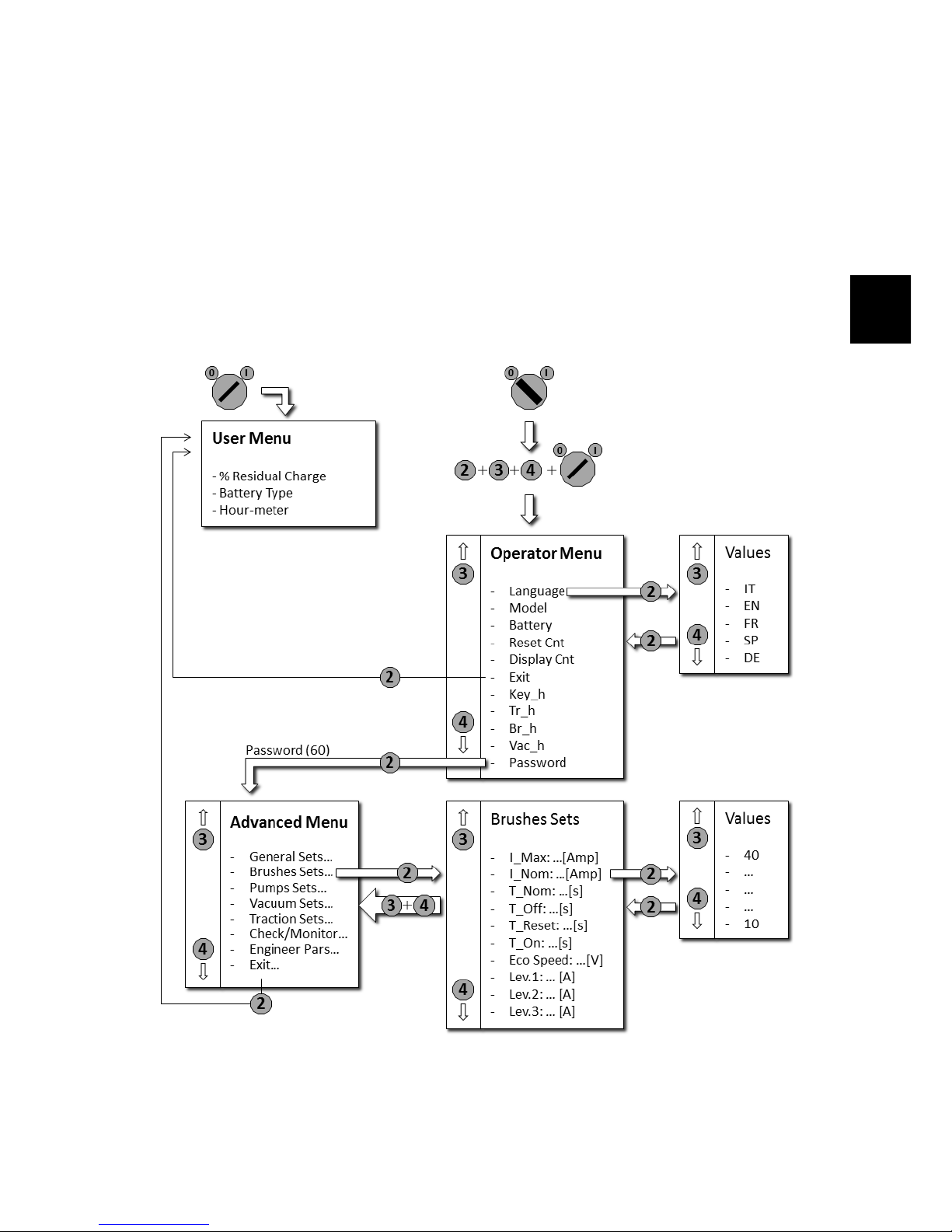
5.7.1 Menu scheme
• Make sure the machine is turned off.
• Press simultaneously the buttons 2,3,4.
• Turn on the machine while holding down the buttons.
• Wait the loading of the Operator Menu.
• For the submenus of the Advanced Menu, refer to the specific tables.
Page 46

5-46
5.7.2 Working Menu
MENU DEFAULT CHOICES DESCRIPTION
General Setup:
Language: ##
IT IT-EN-FR-SP-DESetup language
General Setup:
Mod: #######
MXR . . . Setup type of machine
General Setup:
Battery: ###
GEL GEL-WET-
AGM-GE1WE1
Setup kind of battery
General Setup:
Reset Cnt: #
N Reset partial hourmeter.
General Setup:
Display Cnt: ###
Key KEY-TR Select the kind of hourmeter: key connect to the key - tr.
connect to the traction motor
General Setup:
Exit. . . . . .. . . .
N Exit from the menu.
General Setup:
Key h: #### h:## m
Total hourmeter connect to the key.
General Setup:
Tr h: #### h:## m
Total hourmeter connect to the traction.
General Setup:
Br h: #### h:## m
Total hourmeter connect to the brush motor.
General Setup:
Vac h: #### h:## m
Total hourmeter connect to the vacuum motor.
General Setup:
password: ###
60 This password is necessary to enter into the “Advanced menu”,
utilized by expert technicians only.
5.7.3 Advanced Menu
MENU DESCRIPTION
Options menu:
General sets.
Enter to the general parameters (language, battery. . . ).
Options menu:
Brushes sets.
Enter to the parameters for the brush base.
Options menu:
Pumps sets.
Enter to the parameters of water and chemical pumps (if present).
Options menu:
Vacuum sets.
Enter to the parameters of vacuum motor.
Options menu:
Traction sets.
Enter to the parameters of traction motors.
Options menu:
Check/Monitor.
Enter to view the list of working parameters.
Options menu:
Engineer pars.
Protected parameters (calibrations and factory settings)
Options menu:
Exit. . . ..
Exit and return to the main menu.
Page 47

5-47
General Sets
MENU DEFAULT VALUES DESCRIPTION
General Sets:
Language: ##
IT IT-EN-FR-SP-DESetup the language of the display.
General Sets:
Mod: ###
Mxr . . . Setup of the machine model (Normal version or with dosing
system).
General Sets:
Battery: ##
GEL GEL-WET-
AGM-GE1WE1
Setup of the battery type.
General Sets:
Rst.Cnthr: ##
N Reset partial hourmeter (like on “working menu”).
General Sets:
Rst.Main Cnthr: ##
N Reset total hourmeter (key, brush, vacuum, traction).
Brushes Sets
Parameter Default Min ÷ Max Description
Brushes Sets:
I Max: ## [Amp]
50 20 ÷ 80 Maximum current from the main card to the brush motor.
Brushes Sets:
I Nom: ## [Amp]
22 10 ÷ 40 Rated current; with T Nom manages the amperometric protection
(alarm + stop brush motor).
Brushes Sets:
T Nom: ## [s]
30 1 ÷ 60 Rated timer; with I Nom manages the amperometric protection
(alarm + stop brush motor).
Brushes Sets:
T Off: #.# [s]
0.2 0.0 ÷ 10.0 Delay of switching off of the brush motor when the safety lever is
released.
Brushes Sets:
T Reset: ## [s]
10 0 ÷ 100 Timing of reset amperometric protection (overcurrent).
Brushes Sets:
T On: #.# [s]
0.5 0.0 ÷ 5.0 Delay to switching on of the brush motor when the safety lever is
pressed.
Brushes Sets:
Eco Speed: ## [V]
17 15 ÷ 20 Value of Voltage reduction of brush motor, during ECO mode.
Brushes Sets:
Lev.1: ### [A]
15 5 ÷ 35 Parameter not managed.
Brushes Sets:
Lev.2: ### [A]
25 5 ÷ 35 Parameter not managed.
Brushes Sets:
Lev.3: ### [A]
35 5 ÷ 35 Parameter not managed.
Pumps Sets
Parameter not managed
Page 48

5-48
Vacuum Sets
Parameter Default Min ÷ Max Description
Vacuum Sets:
I Max: ## [Amp]
40 10 ÷ 50 Maximum current from the main card to the vacuum motor.
Vacuum Sets:
I Nom: ## [Amp]
18 5 ÷ 20 Rated current; with T Nom manages the amperometric protection
(alarm + stop vacuum motor).
Vacuum Sets:
T Nom: ## [s]
30 1 ÷ 100 Rated timer; with I Nom manage the amperometric protection (alarm
+ stop vacuum motor).
Vacuum Sets:
T Off: ## [s]
20 0 ÷ 30 Delay of switching on of the vacuum motor when the switch is
pressed.
Vacuum Sets:
T reset: ## [s]
60 0 ÷ 100 Timing of reset amperometric protection (overcurrent).
Vacuum Sets:
Eco Speed: ## [V]
17 15 ÷ 20 Value of Voltage reduction of vacuum motor, during ECO mode
Vacuum Sets:
Rit Up: ## [s]
3 0 ÷ 10 Parameter not managed.
Vacuum Sets:
optional3: ##
0 0 Parameter not managed.
Vacuum Sets:
optional2: ##
0 0 Parameter not managed.
Vacuum Sets:
optional1: ##
0 0 Parameter not managed.
Page 49

5-49
Traction Sets
Parameter Default Min ÷ Max Description
Traction Sets:
Acc Ramp: #.# [s]
1.5 0.5 ÷ 5.0 Acceleration ramp. The time necessary to arrive at the maximum
speed.
Traction Sets:
Dec Ramp: #.# [s]
0.7 0.5 ÷ 5.0 Deceleration ramp. The time necessary to stop the machine when the
safety lever is released.
Traction Sets:
Rev Ramp: #.# [s]
0.7 0.5 ÷ 5.0 The time necessary to invert the way.
Traction Sets:
FW Speed: ### [%]
100 20 ÷ 100 Maximum speed in forward way (expressed in %).
Traction Sets:
BW Speed: ### [%]
60 20 ÷ 100 Maximum speed in reverse way (expressed in % respect the maximum
speed in forward way).
Traction Sets:
Min Speed: ### [%]
0 0 ÷ 20 Minimum speed when the safety lever is pressed.
Traction Sets:
Ref 0: #.# [V]
7 0 ÷ 150 Minimum voltage of the potentiometer when released.
Traction Sets:
Ref FW: #.# [V]
9 5 ÷ 150 Maximum voltage of the potentiometer in forward speed when safety
lever is pressed.
Traction Sets:
Ref BW: ## [V]
9 5 ÷ 150 Maximum voltage of the potentiometer in backward speed when safety
lever is pressed.
Traction Sets:
Ref DB: 0.### [V]
0.200 0.000 ÷ 0.500 Potentiometer dead band
Traction Sets:
Brake Del: ### [S]
1.5 0.0 ÷ 10 Engaging time of electronic brake when the machine is stopped.
Traction Sets:
Mode1 V: ## [%]
50 10 ÷ 100 Voltage setting for the curve speed reduction microswitch.
Traction Sets:
Mode1 I: ## [A]
25 0 ÷ 90 Current intensity setting for the curve speed reduction microswitch.
Traction Sets:
Runaway: ### [Volt]
12 0 ÷ 20 Parameter not managed.
Traction Sets:
optional3: ##
0 0 Parameter not managed.
Traction Sets:
optional2: ##
0 0 Parameter not managed.
Traction Sets:
optional1: ##
0 0 Parameter not managed.
Traction Sets:
I Max: ## [Amp]
70 10 ÷ 70 Maximum output from the main card to the traction motor.
Traction Sets:
I Nom: ## [Amp]
20 5 ÷ 30 Rated Current; with T Nom detect the amperometric protection
threshold. (Alarm + stop traction motor).
Traction Sets:
T Nom: ## [s]
10 1 ÷ 10 Rated T imer; with I Nom detect the amperometric protection thresh-
old. (Alarm + stop traction motor).
Page 50

5-50
Check / Monitor
Check / Monitor:
I Tr: ### [Amp]
Show current of traction motor.
Check / Monitor:
I Br: ## [Amp]
Show current of brush motor.
Check / Monitor:
I Vac: ## [Amp]
Show current of vacuum motor.
Check / Monitor:
V Tr: #### [V]
Show voltage of traction motor.
Check / Monitor:
V Batt: #### [V]
Show battery voltage.
Check / Monitor:
Vref: ### [V]
Show the voltage reference of the traction pedal.
Check / Monitor:
Wtr Pump: ### [%]
Show % speed of water pump.
Check / Monitor:
Det Pump: ### [%]
Show % speed of chemical pump.
Check / Monitor:
BR Temp: ## [C]
Show temperature inside of main card, related to brush/vacuum.
Check / Monitor:
TR Temp: ## [C]
Show temperature inside of main card, related to traction.
Check / Monitor:
TR Ovrld: ### [%]
Show the percentage value of the amperometric protection of traction motor (when 100%
the amperometric protection cuts the current).
Page 51

5-51
5.8 Technical Features
TECHNICAL DESCRIPTION U/M Mxr
Dimension of Battery compartment (l x L x h) mm 362x354x290
Batteries Rated Voltage
V
Ah
2x(12/105)
Maximum batteries weight kg 2x41
5.9 Recommended Spare Parts
PN Description
436265 MAIN CARD 7CFCP000
436267 CONTROL CARD
436268 SERIAL CABLE FOR CONTROL CARD
222367 TRACTION PEDAL ASSEMBLY
210516 COMPLETE KEY SWITCH
409499 MICROSWITCH 3X22 L.C.FLAT
409503 SEAT MICROSWITCH
216691 COMPLETE SEALED MICROSWITCH
436144 EMERGENCY BUTTON
222386 BATTERY CHARGER KIT
Page 52
6-52
Chapter 6
Mechanical Rubbing System
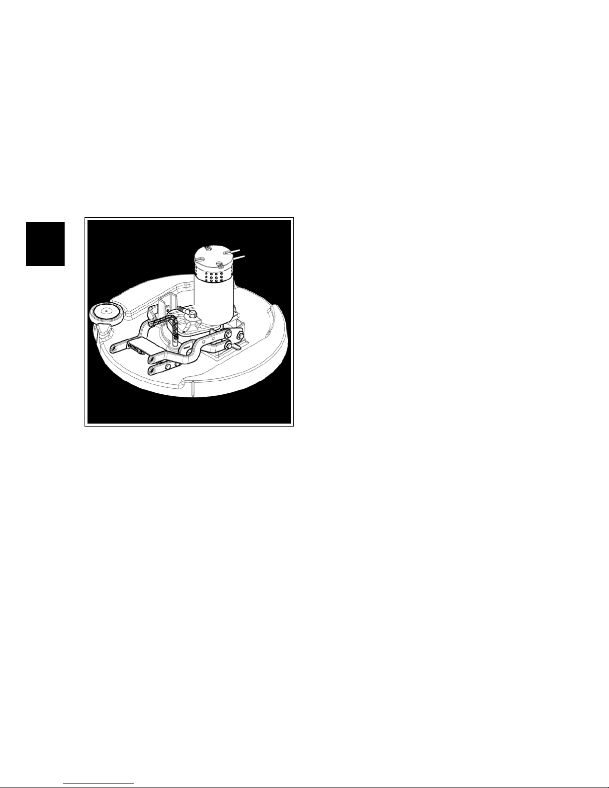
6.1 Structure
1. Motor
2. Bumping Wheel
3. Brush Base
4. Brush coupling Flange
5. Lifting mechanism
6. Brush deck lifting arms
7. Brass bushings
8. Fixing and adjustment plate
6.2 Description:
The washing function of the machine
is obtained by the interaction of the
cleaning solution with the dirt present
on the floor. To facilitate and enhance
this interaction, is used a system of
mechanical rubbing which consists in
a device which rubs on the floor. This
device can be of various nature (pad
or brush), in each case, its function is
to mechanically remove the dirt from
the ground and facilitate the reaction
between the dirt and cleaning solution. A direct current electric motor
connected to a case of gear reduction
provides the rotational movement of the
brush coupling flange. To the flange is
coupled the brush (or the pad holder
provided with pad) that rotates together
with the flange. After lowering the base
to the ground, the brush touches and
rubs on the floor providing the desired
mechanical rubbing.
52
Page 53
6-53
6.3 Adjustments
6.3.1 Fixing and adjustment
plate
The brush deck must be free to move
pivoted to its support so that the brush
acts parallel to the floor. This allows the
brush to evenly lean to the ground and
perform its function properly.
Requirements: Mounted brush, switched
off machine.
Procedure:
• Hook the brush to the base.
• Loosen the adjustment nuts.
• Lower the brush deck to the ground
so that the brush lies uniformly and
parallel to the floor.
• Tighten the adjustment nuts.
6.3.1-82 Loosen the nuts 6.3.1-83 brush deck to the
ground
6.3.1-84 Tighten the nuts
6.3.2 Brush deck lifting cable
Adjust the lifting cable using the appropriate register on the sheath so that
when the base is in the raised position
the brush has a chance to pass under
the base in an easy manner. In any case,
the lowest part of the deck, must have a
height from the ground of at least 7 cm.
6.4 Maintenance and
checks
6.4.1 Motor
Check (to perform every 150h)
The motor should rotate evenly and
smoothly. It’s important that the reduction case is not noisy and that the motor
current consumption is not higher than
the declared on the plate, regardless of
the load which it is subjected. It is necessary that the motor carbon brushes
are always in good condition and show
no signs of abnormal wear.
Maintenance (to perform every 600h)
Motor carbon brushes replacement:
Procedure:
• Put the machine in safe conditions.
• Remove the brush deck from the ma-
chine.
• Loosen the screws that secure the
collar brush guard.
• Disconnect the Carbon brushes
from the input power line to the motor.
• Replace the carbon brushes being
careful not to ruin them during assembly.
• Proceed to the reverse operations to
reassemble it all.
6.4.2 Brass bushings
Check (to perform every 150h)
The brass bushings allow a fluid and
little tiring rotational movement of the
Page 54
6-54
base. To prevent the base is locked
in a position without the possibility of
movement, is important that the brass
bushings are in good condition and
clean. In case of excessive wear it is necessary to proceed with the replacement.
Maintenance (to perform every 900h)
Brass bushings replacement:
Procedure:
• Put the machine in safe conditions.
• Lower the brush deck to the ground
• Loosen the screws that fix the arms
to the brush deck
• Remove the bushings and replace
them with new bushings.
• Proceed to the reverse operations to
reassemble it all, sprinkle the new
bushings with lubricating grease before mounting.
• Adjust to the base once finished.
6.4.2-85 6.4.2-86 Rimozione viti
6.4.2-87 Boccole 6.4.2-88
6.4.3 Bumping Wheel
Check (to perform every 150h)
The bumping wheel (see fig. ??) must be free
to rotate and its diameter must not be
too small due to wear. A bumping wheel
in poor condition can lead to cracking of
the brush base when working skimming
some obstacles (walls, shelving, etc).
If necessary, replace it.
6.4.3-89 Ruota Paracolpi
6.4.4 Brushes Base
Check (to perform every 150h)
The basement must be kept clean and
intact. A ruined basement may be dangerous to the machine and the operator
that uses it.
If necessary, replace it.
6.4.5 Lifting mechanism
Check (to perform every 150h)
The lifting mechanism should be clean
and lubricated. The lubrication of the
cables must be done with silicone spray,
it should not be used any grease or oil
to prevent that the dirt paste itself to
the classics lubricants, and lock the
mechanism. The lubrication of chains
must be done with lubricant grease.
Page 55

6-55
6.4.6 Brush coupling flange
Check (to perform every 150h)
The brush coupling flange is of plastic
material and is not subject to particular wear. Like the other components
its cleanliness is essential to allow
the brush to engage and disengage
smoothly. ’It is also essential that the
brush locking spring has full functionality in order to keep the brush in the
correct position. If necessary, replace
it.
6.4.6-90 Flangia
6.4.7 Fixing and adjustment
plate
Check (to perform every 150h)
The fixing plate must be in good condition, must not show signs of corrosion
or deformation. An incorrect fixing and
adjustment plate does not allow the
entire Mechanical Rubbing group to
work properly.
6.4.7-91 Plate
Page 56

6-56
6.5 Technical Features
TECHNICAL DESCRIPTION U/M Mxr
Working width mm 560
Working capacity, up to m2/h 2632
Number of brushes Nr 1
Maximum diameter of the active part of the
brush
φ mm 560
Brush turns rpm 180
Brush motor voltage V 24
Brush motor power W 450
Max weight on brush kg 16
6.6 Consumable Spare Parts
PN Description φ (mm) Bristle φ Bristle (mm) Colour
436232 BRUSH PPL 0,3 560 PPL 0,3 Blue
436233 BRUSH PPL 0,6 560 PPL 0,6 White
436234 BRUSH PPL 0,9 560 PPL 0,9 Black
436235 BRUSH TYNEX 560 ABRASIVE 0,9 Gray
436236 PAD HOLDER 535 - - -
Carbon Brushes
409412 BR.MOT.CARBON BR. - - -
6.7 Recommended Spare parts
PN Description
222452 GEAR MOTOR 24V 400W 140RPM H2O W/MOLEX
436120 BASE BUMPER WHEEL D=100 H=20
436124 BRUSH FLANGE
Page 57

7-57
Chapter 7
Drying System
7.1 Structure
1. Squeegee
2. Squeegee Support
3. Vacuum Hose
4. Recovery Tank
5. Filter and Floating
6. Vacuum Motor
7. Drain Hose
7.2 Description
The machine dries the floor using an integrated Drying System. After the washing, the solution used with the mechanical action of the brush to remove the
dirt, is collected by a system which vacuum it out from the floor. The system
is basically made by a vacuum motor
which produces an underpressure in the
system. This underpressure causes an
air flow which flows in the whole vacuum circuit. The air that flows in the
squeegee (when it is lowered on the floor)
allows it to collect the water on the floor
mixing it with the water and, via the vacuum system, is brought to the recovery tank. In the recovery tank the water mixed with the dirt stops and the
air keep flowing throughout the circuit
reaching the vacuum motor and being
discharged in the environment via the
exhaust manifold.
57
Page 58
7-58
7.3 Adjustments
7.3.1 Squeegee Support
The Squeegee Support has to be adjusted with the Squeegee fitted on, lowered on the floor and vacuum system on.
The goal of the adjustment is to let the
squeegee blade be angled 45 degrees to
the floor for its whole length.
To obtain the proper squeegee adjustment act on the wheels of the squeegee
support (1) to move the squeegee in the
A direction and on the inclination screw
(2) to adjust the B movement.
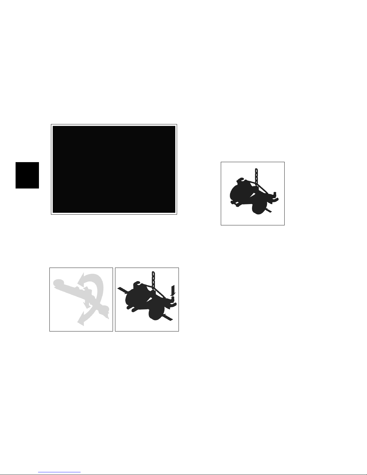
7.3.1-92 Movements 7.3.1-93 Adjustments
Procedure
• Put the machine in safe conditions.
• Loosen the nuts holding the wheels
of the squeegee support
• interpose between the squeegee
wheels and the floor a thickness of
approximately 1.5 mm (±0,1mm)
• Lower the squeegee on the floor
keeping the squeegee rubbers perfectly vertical.
• Fix the wheels of the squeegee support by tightening the nuts loosened
earlier
• Turn the screw (2) to adjust the B
movement (Figure 1) until the correct setting is obtained.
• Verify with a functional test the obtained adjustment.
7.3.1-94 Wheel locking
nuts
7.3.2 Squeegee lifting cable
Adjust the squeegee lifting cable using
the adjuster on the sheath so that when
the squeegee is lowered to the floor, it
can move laterally in all its possible excursion.
Page 59

7-59
7.4 Maintenance and
Checks
7.4.1 Squeegee
Check (to perform every 4h)
To have a good performance of the
squeegee the blades have to be in a
good conditions. The squeegee chamber
and the squeegee adapter have to be
clean and completely free from debris.
Blades have to adhere perfectly to the
squeegee body and have to be kept in
that position by the plastic blade holder
which are kept by the plastic wing nuts.
Maintenance (to perform every 45h)
• Put the machine in safe conditions.
• Remove the squeegee from the ma-
chine.
• Rotate the wing nut that block the
blade holders.
• Remove the blade holder.
• Remove the front blade and replace
it with a new one.
• Repeat the same operations for the
rear blade. The rear blade can be
used 4 times (one for each edge) before being replaced.
• Proceed at reverse to reinstall properly the blade holders.
7.4.2 Squeegee Support
Check (to perform every 150h)
The squeegee support has to be completely free to move to lie perfectly on the
floor. It is important that it can rotate
freely around the fixing central axle and
it is properly pressed on the floor by the
gas spring.
7.4.1-95 Rear Rubber 7.4.1-96
7.4.1-97 7.4.1-98 Front Rubber
7.4.1-99 7.4.1-100
Maintenance (to perform every 600h)
• Put the machine in safe conditions.
• Remove the squeegee from the
squeegee support.
• Completely unscrew the nuts holding the squeegee support wheels.
• Remove and replace the squeegee
support wheels.
• Proceed at reverse to reinstall the
parts.
• At the end of the assemblying perform the proper squeegee adjustment (see section 7.3.1 at page 58).
Page 60
7-60
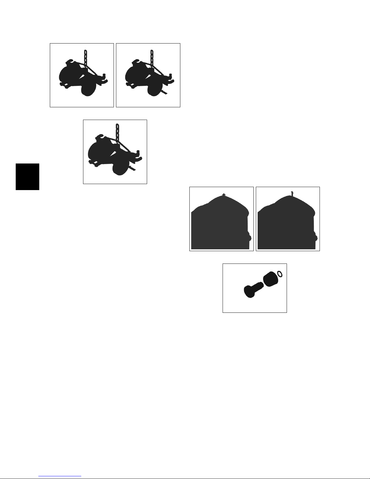
7.4.2-101 7.4.2-102
7.4.2-103
7.4.3 Vacuum Hose
Check (to perform every 4h)
The vacuum hose has to be clean and
intact. It is mandatory that the hose has
no crack to not decrease the underpressure. The suction hose is particularly
sensitive in the coupling areas between
the pipe and couplings and in tight
curves.
7.4.4 Filtro e Galleggiante
Check (to perform every 4h)
The filter has to be clean and it is important that nothing blocks or reduces
the floater mobility. The filter has to be
clean to avoid that water or dirt goes
inside the vacuum motor, the floater
has to be free to move and has to block
completely the air flow when it is in
blocking position (UP).
Maintenance (to perform every 4h)
• Put the machine in safe conditions.
• Check that the recovery tank is com-
pletely empty.
• Remove the recovery tank cover.
• Unscrew the filter and the floater.
• Remove the Gasket.
• Replace the Gasket.
• Open the cap of the filter body.
• Remove and clean (replace if neces-
sary) the filter.
• Proceed at reverse to restore the
parts.
7.4.4-104 7.4.4-105
7.4.4-106
Page 61
7-61
7.4.5 Recovery Tank
Check (to perform every 150h)
The recovery tank has to be clean and
has not to have cracks or, in general,
any kind of damage. The Lid housing
has to be even and flat to allow the
gasket to adhere perfectly to the tank
to avoid any air infiltration. The hose
fittings have to be in optimum condition
in order to avoid any dirty water leakage or any pressure drop during the job.
7.4.5-107 7.4.5-108
7.4.5-109
7.4.6 Vacuum Motor
Check (to perform every 150h)
The vacuum motor with the inlet completely open has to absorb between 10
and 18A. The motor carbon brushes
have to be in good conditions and their
length has to be no lower than 6-8mm.
The motor contacts have to be clean,
they have not to be oxidized or have
any kind of damage. The motor wires
insulation has to be flexible and intact
to avoid any possible short circuit. The
magnetic circuit of the motor has to be
in good conditions and clean.
Maintenance (to perform every 450h)
• Put the machine in safe conditions.
• Disassemble the motor from the ma-
chine (see section 4.3.6 at page 24).
• Remove the cooler fan plastic cover
from the motor.
• Slip off the motor carbon brushes
• Replace the worn out carbon
brushes with new ones.
• Proceed at reverse to restore the
parts.
Page 62
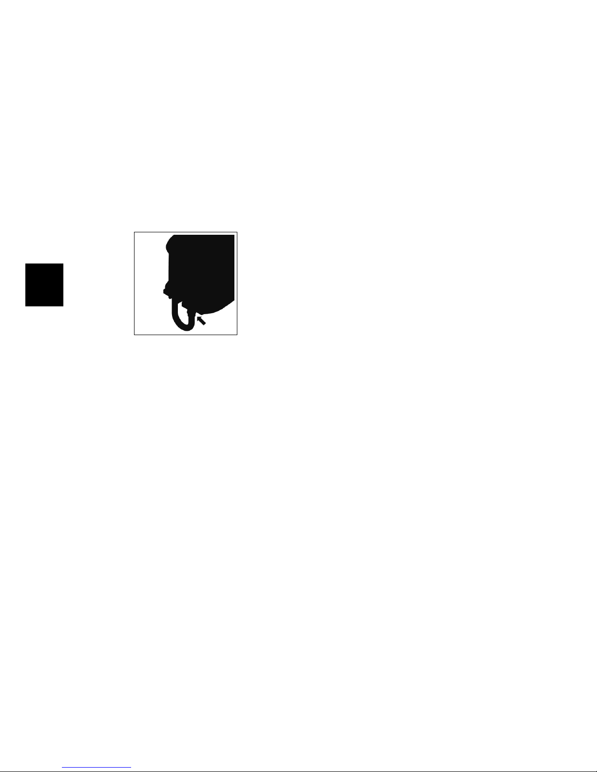
7-62
7.4.7 Drain Hose
Check (to perform every 4h)
The Drain Hose has to be perfectly fitted
in the recovery tank fittings in order to
avoid any dirty water leakage. The Drain
Cap has to seal perfectly the hose to
avoid any pressure drop or dirty water
leakage. The Drain Manifold has to
be flexible and has to have no cracks
to avoid any break down during the
bending to drain the machine.
7.4.7-110 Fase 1
Page 63

7-63
7.5 Technical Features
TECHNICAL DESCRIPTION U/M Mxr
Squeegee width mm 705
Optional Squeegee width mm 800
Vacuum Motor Stages Nr 2
Squeegee adapter type Vertical
Vacuum Motor Power W 310
Vacuum Motor Voltage V 24
Vacuum Motor Depression mmH2O 970
Recovery Tank l 75
7.6 Consumable Spare Parts
PN Description
Squeegee 705mm
219451 RUBBER KIT 33 SHORE
219452 RUBBER KIT 40 SHORE PU
219453 LATEX RUBBER KIT
427251 WHEEL D=80 L=23 SUPERLAN GRAY
Squeegee 800mm
221391 RUBBER KIT 33 SHORE SP=4
221392 RUBBER KIT 40 SHORE PU SP=4
221393 RUBBER KIT LATEX SP=4
427251 WHEEL D=80 L=23 SUPERLAN GRAY
Carbon Brushes
424210 VACUUM MOTOR CARBON BRUSHES
7.7 Recommended Spare Parts
PN Description
222453 VACUUM MOTOR 24V 310W H950 2ST
436198 VACUUM HOSE D38x980
436196 DRAIN HOSE D.38x1474 D.50 W/CAP
430957 STRAIGHT ADAPTER D=40 TERGI 2010
436120 BUMPER WHEEL D=100 H=20
436190 GAS SPRING 16-1 L=146 L=40 F=150 N
436195 FLOATER PROTECTION D=62 d=47 S=3
436361 FILTER D.103x25 AU PPI 10
Page 64

8-64
Chapter 8
Machine Frame and Traction System
8.1 Structure
• Squeegee and Brushdeck Levers
• Steering column
• Front Wheel
• Frame
• Rear Wheels
• Traction Motor
8.2 Description
The frame is a unique structure in
painted steel. On it are coupled the
steering system including the levers for
the activation of the drying system and
mechanical friction system, and the
traction system. The steering system
is composed by a steering column connected to a steering wheel , which acts
directly on the front wheel . The steering is ensured by a pinion and a crown,
connected by a chain. The pinion is
welded directly onto the steering, while
the crown is installed on the assembly
front wheel. On top of the steering column , there are the levers for the activation of the squeegee and the mechanical friction system. To ensure the proper
functioning of the two systems, in the
steering column are installed some microswitches that act directly on the affected systems. The traction of the machine is guaranteed by an electric motor installed in combination with a gear,
whose output shafts act directly on the
rear wheels of the machine, ensuring
traction. The gear motor is equipped
with an electrobrake which ensures the
immobility of the machine when it is not
moving. Both the front wheel the rear
wheels are non-marking and antiskid.
64
Page 65

8-65
8.3 Adjustments
8.3.1 Scrubdeck Lever and
Squeegee Lever
The levers have to be adjusted so as to
ensure the smooth lifting and lowering
of the brush deck and squeegee. At the
same time, they must activate properly
the microswitches of the vacuum motor
and of the brush motor.
Procedure
Put the machine in safe conditions.
Movements adjustment:
• Remove the steering wheel cover.
• Act on the sheaths adjusting nuts to
increase or decrease the length.
• Check that with the raised levers
the squeegee and the brushdeck rise
and lowered properly without interfering with the frame.
• Restore the steering wheel cover.
Microswitch Actuation:
• Remove the steering wheel cover.
• Make sure that the microswitches
are correctly pressed when the lifting/lowering levers of the squeegee
and the brush deck are moved.
• Adjust the microswitches by the
screws so that they are properly
pressed when operating the levers.
• Restore the steering wheel cover.
8.3.2 Steering wheel
The steering wheel should be adjusted
when there is too much clearance between the chain that acts on the pinion connected to the steering bar of the
steering wheel and the crown mounted
on the front wheel.
8.3.1-111 Movements adjustment
8.3.1-112 Microswitch activation
Procedure
• Put the machine in safe conditions.
• Remove the steering wheel cover.
• Loosen the nuts securing the bottom
support plate of the steering shaft.
• Release the grains locking nuts, set
the optimum tension of the chain by
acting on the grains, lock the adjustment by tightening the locking nuts.
• Once found the optimum tension
retighten the fixing nuts to lock the
bottom supporting plate of the steering shaft.
• Restore the steering wheel cover.
8.3.2-113 Steering adjustment
Page 66

8-66
8.4 Maintenance and
Checks
8.4.1 Levers
Check (to perform every 150h)
The operating levers of the squeegee and
the brush deck, must always be operated with ease and without excessive
effort from the operator.
Maintenance (to perform every 600h)
Replacement of the brass laminated
bushings:
• Put the machine in safe conditions.
• Remove the steering wheel cover.
• Lower the squeegee and the brush
deck to the floor.
• Unscrew the screws that hold the
levers to the steering column and remove the internal levers.
• Proceed with the removal of the
bushings and replace them with new
bushings.
• Restore the steering wheel cover.
8.4.1-114 Steering adjustment
8.4.2 Steering
Check (to perform every 150h)
The steering must always be precise and
free to rotate smoothly. Check that the
ring and the pinion coupling chain has
no excessive clearance and is not noisy.
Maintenance (to perform every 600h)
Periodically grease the ring and pinion
coupling chain. If the chain is too loose,
adjust the chain tension as described in
the ”Settings” paragraph.
8.4.2-115 Steering adjustment
8.4.3 Front Wheel
Check (to perform every 150h)
The wheel must be free to rotate
smoothly without friction. The wheel
surface, must always be in good condition.
Maintenance (to perform every 600h)
Periodically check the wheel bearings
status. Periodically grease the wheel
bearings.
8.4.4 Traction motor
Check (to perform every 150h)
During normal running, the current
consumption must be between 5 and 7
Amps.
ATTENTION – At the start the absorption
current of the motor is much higher.
Page 67

8-67
The carbon brushes of the traction motor drive must be at least 6-8 mm long.
The isolation of the power cables of the
motor and the electrobrake, must be
complete in all their parts and do not
show signs of cracks. The cables must
demonstrate flexibility. The activation
lever of the electrobrake should activate
only if a certain push is applied.
• With electrobrake engaged and the
machine not powered, the machine
itself should not move.
• With electrobrake engaged and the
machine powered but not moving,
the machine itself should not move.
• With electrobrake engaged, when
acting the traction, the machine itself have to move.
Lifting the machine to make the rear
wheels neutral, by spinning a wheel (in
any sense) the other should turn in the
opposite direction.
Maintenance (to perform every 600h)
Motor carbon brushes replacement:
• Put the machine in safe conditions.
• Remove the protection plastic cov-
ers.
• disconnect the carbon brushes from
the electrical connection to the motor.
• Replace the carbon brushes being
careful not to ruin them during assembly.
• Proceed to reverse operations for reassembly.
8.4.5 Rear Wheels
Check (to perform every 150h)
The wheel surface, must always be in
good condition.
Page 68

8-68
8.5 Technical Features
TECHNICAL DESCRIPTION U/M Mxr
Traction motor Voltage V 24
Traction motor Power W 300
Traction wheel (num/diam/width) Nr/φmm/mm 1/175/60
Rear wheels (num/diam/width) Nr/φmm/mm 2/225/64
Wheels material Thermoplastic Polyurethane
Wheel hardness Sh 85
Maximum forward speed km/h 5.6
Maximum reverse speed km/h 3.3
8.6 Consumable spare parts
PN Description
436222 FRONT WHEEL D=175 d=20 S=60 WITH BEARINGS
426460 REAR WHEEL D=225 L=69
Carbon Brushes
422462 TR. MOTOR CARBON BRUSHES
8.7 Suggested spare parts
PN Description
222454 TRACTION MOTOR 24V 300W 115G 18A EL.BR.+MOLEX
Page 69
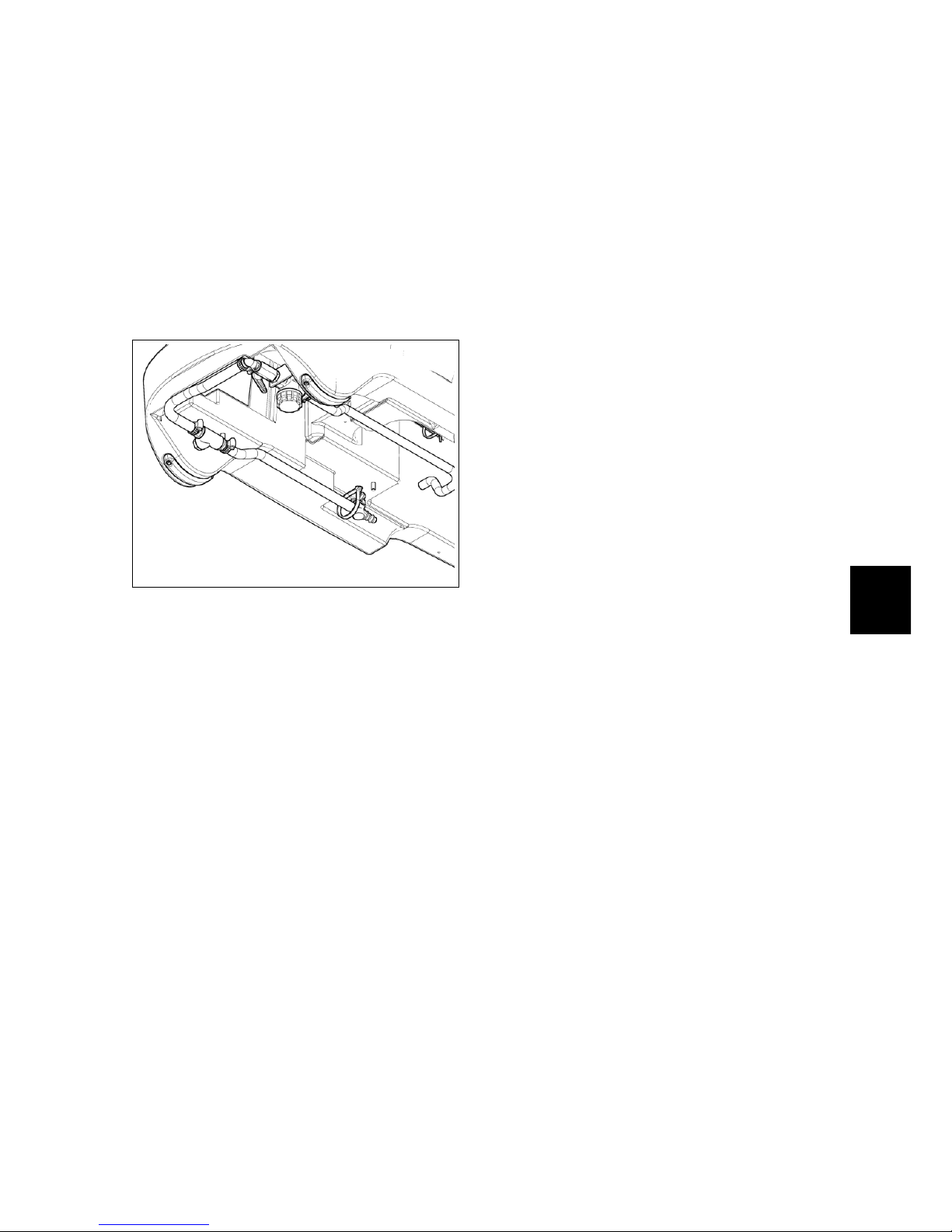
9-69
Chapter 9
Cleaning Solution Supply System
9.1 Structure
1. Solution Tank
2. Hoses
3. Water Valve
4. Solution Filter
5. Solenoid Valve
6. Distributor
9.2 Description:
The Cleaning Solution Supply System
is made by a tank commonly called
solution tank or clean water tank. In
this tank the clean water is mixed with
the detergent to create the cleaning
solution that the machine will use to
clean. The solution is then canalized to
the filter and the water valve. The filter
is used to stop debris that could stuck
the hose system and compromise the
proper functioning of the system, the
water valve is used to adjust the solution
that will fall on the floor in order to have
the correct amount of solution required
for washing. The water valve is placed
upstream of the filter to allow the filter
cleaning even with fully or partially full
solution tank. Once passed through the
water valve the solution arrive to the
solenoid valve that blocks the delivery
when the brush is not working and allow
the flow while brush works. The end
of the solution path is the distributor
that canalizes the flow in the middle of
the brush. The solution tank is also
equipped with a drain hose to empty it
in case of need.
69
Page 70
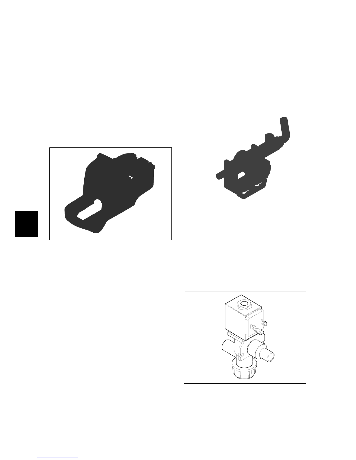
9-70
9.3 Maintenance and
Checks
9.3.1 Solution Tank
Check (to perform every 50h)
The solution tank has to be clean and
intact. It has not to have cracks or any
other kind of damage. Verify, when the
tank is completely filled up, that there
are not leakage. If necessary replace the
Solution Tank.
9.3.2 Hoses
Check (to perform every 50h)
Every single hose has to be intact and
has not to be worn out. It is extremely
important that the hoses kept the original flexibility and they haven’t suffered
any chemical reaction with the detergent
used with the machine. If necessary
proceed with the replacement of the
damaged hoses.
9.3.3 Water Valve
Check (to perform every 50h)
It is extremely important that when
adjusted at minimum the valve blocks
completely the water flow and that the
adjustment lever is mechanically free to
move for its while stroke.
9.3.4 Clean Water Filter
Check (to perform every 4h)
The filter has to be periodically cleaned.
When it is fitted on the machine no
leakage has to be present. The filter
cartridge has to be intact and has not to
present any anomaly.
9.3.5 Solenoid Valve
Check (to perform every 50h)
The solenoid valve has to block completely the solution flow when the brush
deck is not working. Viceversa it has to
grant the full flow rate when the brush
deck is working.
Page 71

9-71
9.3.6 Distributor
Check (to perform every 150h)
The distributor has to be intact and has
to grant the proper solution flow without
any leakage in the gearbox.
Page 72

9-72
9.4 Technical Features
TECHNICAL DESCRIPTION U/M Mxr
Solution Tank l 65
Clean Water Filter Steel cartridge
Water Valve Steel ball valve
9.5 Recommended Spare parts
Codice Descrizione
407887 COMPLETE SOLENOID 24V 1/2” ACL 3
212616 CLEAN WATER FILTER 1/2” F/F COMPL.
420950 GASKET OR 2X38 MM
Page 73

9-73
Part IV
Accessories and Add-On
73
Page 74
10-74
Chapter 10
Accessories
10.1 Accessories List
• Blinking Kit
• Onboard Charger Kit
• Splashguard Kit
• Cleaning Accessories Kit
10.2 Blinking Kit - 222471
10.2.1 Description
The kit consists of a alarmflashing yellow light. Although this light is not considered mandatory by law, if the user requires it for their particular needs is possible to equip the machine with this accessory.
10.2.2 Installing instructions
• Unplug the power cable of the batteries.
• Place the rubber circular base provided with the kit at the predisposition on the rear side of the recovery
tank near the entrance of the suction hose. Make sure the slot in the
rubber base is fixed at the trimmer
guard on the recovery tank.
• Place the blinker on the rubber base
so as shown in the figure so as
to match between rubber base and
body of the blinker the three holes
for the fixing screws crosswise.
• Using a Phillips screwdriver to
tighten the 3 screws supplied with
the kit, taking care to use the silicone paste (red paste) previously applied on the screws.
10.2.2-116 10.2.2-117
10.2.2-118
• Remove the two screws of the brush
rear support and remove the support.
• Accompanying the supply cable of
the blinker so that it is placed laterally to the suction hose.
• Accompany the supply cable of the
blinker inside the battery compartment through the slot on the rear of
the solution tank. The entry point is
the same for which the suction hose
passes.
74
Page 75
10-75
10.2.2-119 10.2.2-120
10.2.2-121
• Connect the power cable connector
of the blinker to the of the connector
of the wiring inside the battery compartment.
• Tighten the brush rear support.
• Reconnect the battery cables and
proceed to a functional check of the
machine.
10.2.2-122 10.2.2-123
10.2.2-124
Page 76

10-76
10.3 Onboard Charger Kit
- 222386
10.3.1 Description
The machine is available in ”CB” version which is the version with the built
in charger. Anyway, in a standard machine, the battery charger can be fitted
acting as follows.
10.3.2 Machine Preparation
Before to start the kit installation is
mandatory to put the machine in safe
condition. Release the brush, switch off
the machine and unplug the batteries.
10.3.3 Installing instructions
• Fit the charger into the housing and
fasten it with the 4 supplied screws,
taking care to add the two washers
on the slots.
• Mount the base on the housing,
tightening the screw in the insert.
Connect the battery charger cables1:
• Connect the charger power cable to
the cables ”XCB” of the machine
harness.
• Connect the safety contact cables to
the cables ”XCBR” of the machine
harness.
1
Refer also to the Electric Scheme
• Secure the cables to the clips with
plastic ties.
• Reconnect the battery cables and
proceed to a functional check of the
machine.
Page 77

10-77
10.4 Splashguard Kit 222480
10.4.1 Description
Even if the solution output is in the middle of the brush, on particular not absorbing kind of floors could be necessary a Splashguard in order to avoid the
dispersing of the solution outside of the
scrubbing path. The Functioning of this
kit is absolutely equal to the other ones
similar to it.
10.4.2 Installing instructions
• Release the brush, switch off the
machine and unplug the batteries.
• Lower the brush deck.
• Mount the splashguard blades sup-
plied with the kit. The spring should
be attached to the side without slot
(traditional hole). The side with the
loop has to be fastened to the deck
first.
10.4.2-125 10.4.2-126
10.4.2-127 10.4.2-128
• Fix the splashguard blades to the
deck. Drill two holes φ 4 matching
the grooves in the front of the deck.
The height of the hole from the bottom side of the base should be 13
mm.
• Fix the blades using the M4 screws
provided with the kit. Tighten the
nut and locknut.
• Determine the position of the remaining fixing holes Ø4 starting
from the grooves on the rear side of
the deck.
Consider the drive position as a
reference.
Keep the hole 13 mm height from
the bottom side of the deck.
10.4.2-129 10.4.2-130
10.4.2-131 10.4.2-132
• Make the left side hole 8 cm from the
corresponding rear groove.
• Make the right side hole 10 cm from
the corresponding rear groove.
• Once drilled the fixing holes, attach
the blades and the splashguard rubbers by pulling the spring and using
the M4 screws provided with the kit.
Attach nuts and locknuts.
Page 78

10-78
• Reconnect the battery cables and
proceed to a functional check of the
machine with a brush attached to
the base.
10.4.2-133 10.4.2-134
10.4.2-135 10.4.2-136
10.5 Cleaning Accessories
Kit - 222472
10.5.1 Description
The set of the cleaning accessories allows to equip the machine with a coupling system for many accessories for
manual cleaning. These can significantly reduce downtime while increasing the productivity of the machine and
make it much more comfortable the
working shift of the operator.
10.5.2 Installing instructions
• Unplug the power cable of the batteries.
• Remove the front carter of the machine by removing the six support
screws.
• Drill four holes Ø5 at predispositions
on the back of the front carter.
• Place the front support bracket as
shown in the image (upwards slot
of the bracket). Secure the bracket
with the four M5 provided screws.
• Tighten the screws with the washers
and locking nuts included in the kit.
Restore the front carter of the machine.
10.5.2-137 10.5.2-138
10.5.2-139 10.5.2-140
Page 79
10-79
• The accessories group is grafted in
pressure.
• The side bracket must be inserted in
predisposition located below the recovery tank.
• The side bracket is provided with a
slot and a fixing hole.
• Install the bracket as shown in the
figure and secure the bracket with
the two M5 screws supplied with the
kit.
10.5.2-141 10.5.2-142
10.5.2-143 10.5.2-144
• Reconnect the battery cables and
proceed to a functional check of the
machine.
Page 80

10-80
10.6 Consumable Spare Parts
PN Description
435438 SPLASHGUARD RUBBER L=500
Page 81

10-81
Fimap S.p.A.
Workshop Handbook MXR
Fimap S.p.A. Via Invalidi del Lavoro, 1 - 37050 S.Maria di Zevio Verona - ITALY
Tel. +39 045 6060411 - Fax +39 045 6060417
Edizione: January 15, 2014
 Loading...