


USE AND MAINTENANCE MANUAL
MMX B-BT 2014
ED. 08-2014 EN
TRANSLATION OF
THE ORIGINAL
INSTRUCTIONS
Doc. 10016247
Ver. AE

CONTENTS
CONTENTS ................................................................................................................................................................................................................................... 1
SYMBOLS USED IN THE MANUAL ............................................................................................................................................................................................ 3
QUICK REFERENCE (ELECTRONIC DOCUMENT): .................................................................................................................................................................. 3
1. BOOKMARKS: .................................................................................................................................................................................................................... 3
2. LINK PAGE: ........................................................................................................................................................................................................................ 3
PURPOSE AND CONTENT OF THE MANUAL ........................................................................................................................................................................... 4
TARGET GROUP.......................................................................................................................................................................................................................... 4
STORAGE OF USE AND MAINTENANCE MANUAL ................................................................................................................................................................. 4
ON CONSIGNMENT OF THE APPLIANCE ................................................................................................................................................................................. 4
INTRODUCTORY COMMENT ...................................................................................................................................................................................................... 4
IDENTIFICATION DATA ............................................................................................................................................................................................................... 4
TECHNICAL DESCRIPTION ........................................................................................................................................................................................................ 4
INTENDED USE ............................................................................................................................................................................................................................ 4
SERIAL NUMBER PLATE ............................................................................................................................................................................................................ 4
SAFETY ........................................................................................................................................................................................................................................ 4
GENERAL SAFETY REGULATIONS .......................................................................................................................................................................................... 5
TECHNICAL DATA ....................................................................................................................................................................................................................... 6
SYMBOLS USED ON THE APPLIANCE ..................................................................................................................................................................................... 7
PREPARATION OF THE APPLIANCE ........................................................................................................................................................................................ 9
1. HANDLING THE PACKED APPLIANCE ............................................................................................................................................................................ 9
2. HOW TO UNPACK THE MACHINE ................................................................................................................................................................................... 9
3. HOW TO TRANSPORT THE APPLIANCE ........................................................................................................................................................................ 9
4. COMPONENT POSITIONING .......................................................................................................................................................................................... 10
5. APPLIANCE SAFETY ....................................................................................................................................................................................................... 10
6. TYPE OF BATTERY ......................................................................................................................................................................................................... 11
7. BATTERY HOPPER MAINTENANCE AND DISPOSAL .................................................................................................................................................. 11
8. INSERTING BATTERIES INTO THE DEVICE ................................................................................................................................................................. 11
9. BATTERY CHARGER CONNECTION (only for systems without CB) ............................................................................................................................. 12
10. BATTERY CHARGER CONNECTION (only for systems with CB) .................................................................................................................................. 13
11. HOUR METER .................................................................................................................................................................................................................. 14
12. BATTERY CHARGE LEVEL INDICATOR ........................................................................................................................................................................ 14
13. FORWARD MOVEMENT AT WORK SPEED (only for BT system) ................................................................................................................................. 14
14. FILLING THE SOLUTION TANK ...................................................................................................................................................................................... 15
15. DETERGENT SOLUTION (only for versions without FSS) .............................................................................................................................................. 15
16. FILLING THE DETERGENT CANISTER (only for systems with FSS) ............................................................................................................................. 15
17. ASSEMBLING THE SQUEEGEE ..................................................................................................................................................................................... 16
18. BRUSH ASSEMBLY (only for single-disc versions) ......................................................................................................................................................... 17
19. BRUSH ASSEMBLY (only for twin-disc versions) ............................................................................................................................................................ 17
20. ASSEMBLING THE SPLASH GUARD ............................................................................................................................................................................. 18
PREPARING TO WORK ............................................................................................................................................................................................................. 19
1. PREPARING TO WORK ................................................................................................................................................................................................... 19
2. TRIGGERING THE DOSING SYSTEM (only for FSS system) ........................................................................................................................................ 19
WORK ......................................................................................................................................................................................................................................... 21
1. STARTING WORK ............................................................................................................................................................................................................ 21
2. DETERGENT ADJUSTMENT (only for versions without FSS) ........................................................................................................................................ 21
3. DETERGENT ADJUSTMENT (only for versions with FSS) ............................................................................................................................................. 21
4. "ECO MODE" DEVICE ..................................................................................................................................................................................................... 22
5. OVERFLOW DEVICE ....................................................................................................................................................................................................... 22
AT THE END OF THE WORK .................................................................................................................................................................................................... 23
DAILY MAINTENANCE .............................................................................................................................................................................................................. 24
1. EMPTYING THE RECOVERY TANK ............................................................................................................................................................................... 24
2. EMPTYING OF THE SOLUTION TANK ........................................................................................................................................................................... 24
3. CLEANING THE SQUEEGEE BODY ............................................................................................................................................................................... 24
4. CLEANING THE BRUSH .................................................................................................................................................................................................. 25
5. CLEANING THE VACUUM MOTOR FILTER FLOAT ...................................................................................................................................................... 26
6. CLEANING THE SOLUTION TANK FILTER .................................................................................................................................................................... 26
WEEKLY MAINTENANCE ......................................................................................................................................................................................................... 27
1. CLEANING THE RECOVERY TANK ................................................................................................................................................................................ 27
2. CLEANING THE SOLUTION TANK ................................................................................................................................................................................. 27
3. CLEANING THE VACUUM HOSE .................................................................................................................................................................................... 28
4. CLEANING THE DETERGENT CANISTER (only for system with FSS) .......................................................................................................................... 28
EXTRAORDINARY MAINTENANCE ......................................................................................................................................................................................... 29
1. REPLACING THE SQUEEGEE RUBBERS ..................................................................................................................................................................... 29
2. ADJUSTING THE SQUEEGEE ........................................................................................................................................................................................ 30
3. REPLACING THE BRUSH ............................................................................................................................................................................................... 30
4. REPLACING THE BRUSH HEAD SPLASH GUARD ....................................................................................................................................................... 31
5. RINSING THE DOSING SYSTEM (only for FSS system) ................................................................................................................................................ 31
TROUBLESHOOTING ................................................................................................................................................................................................................ 33
1. AN ALARM MESSAGE APPEARS ON THE CONTROL DISPLAY ................................................................................................................................. 33
Page 1

2.
THE APPLIANCE DOES NOT SWITCH ON .................................................................................................................................................................... 33
3. THE BATTERIES ARE NOT CHARGED CORRECTLY .................................................................................................................................................. 33
4. THE DEVICE HAS A VERY LOW OPERATING AUTONOMY ........................................................................................................................................ 33
5. THE APPLIANCE DOES NOT MOVE .............................................................................................................................................................................. 34
6. INSUFFICIENT WATER ON THE BRUSHES .................................................................................................................................................................. 34
7. THE DEVICE DOES NOT CLEAN CORRECTLY ............................................................................................................................................................ 34
8. THE SQUEEGEE DOES NOT DRY PERFECTLY ........................................................................................................................................................... 34
9. EXCESSIVE FOAM PRODUCTION (RECOVERY TANK) ............................................................................................................................................... 35
10. THE VACUUM MOTOR DOES NOT FUNCTION ............................................................................................................................................................ 35
11. BYPASSING THE WATER SYSTEM SUPPLY PUMP (only for FSS versions) ............................................................................................................... 35
DISPOSAL .................................................................................................................................................................................................................................. 36
CHOOSING AND USING BRUSHES ......................................................................................................................................................................................... 37
EC DECLARATIONS OF CONFORMITY ................................................................................................................................................................................... 38
Page 2

The descriptions contained in this document are not binding. The company therefore reserves the right to make any
modifications at any time to elements, details, or accessory supply, as considered necessary for reasons of improvement
or manufacturing/commercial requirements. The reproduction, even partial, of the text and drawings contained in this
document is prohibited by law.
The company reserves the right to make any technical and/or supply modifications. The images are for reference
purposes only, and are not binding in terms of design and supply.
SYMBOLS USED IN THE MANUAL
Open book symbol with an "i"
Indicates the need to consult the instruction manual.
Open book symbol:
Used to tell the operator to read the manual before using the appliance.
Warning symbol.
Carefully read the sections marked with this symbol and observe the indications, for the safety
of the operator and the appliance.
Danger symbol.
Indicates the presence of substances or preparations that may destroy living tissue upon
contact.
Warning symbol:
Presence of gaseous substances with a low flashpoint.
Disposal symbol.
Carefully read the sections marked with this symbol for the disposal of the machine.
Warning symbol:
indicates that the packed product should be handled with suitable lifting means that comply with
the legal requirements.
Indoor symbol.
The operations preceded by this symbol must be rigourously carried out in a dry, indoor area.
Recycling symbol.
When recycling the device, carefully read the sections marked with this symbol.
QUICK REFERENCE (ELECTRONIC DOCUMENT):
For quick reference of the electronic documents, use the Bookmarks and
Link Pages:
1. BOOKMARKS:
Activate the "Bookmarks" panel of the interface browser, clicking the
related icon (01), the icon may vary depending on the version of the
Acrobat viewer.
To view the desired paragraph, simply click on the title in the browser (02)
that will take you to the desired destination.
2. LINK PAGE:
To view the desired paragraph in the content of the document, simply click
on the title of the paragraph that will take you to the desired destination.
NB:
if the text directs you to a specific chapter or paragraph, you can go
directly to that page by clicking on the name of the paragraph in question
(the title is written in capital letters and underlined).
To return quickly to the contents of the document, simply click on the
company logo at the top of this page, and it will sends you back to the
desired destination.
01
02
Page 3

PURPOSE AND CONTENT OF THE MANUAL
The aim of this manual is that of providing customers with all information
needed to use the appliance in the most appropriate, autonomous and
safe way. It includes information concerning technical aspects, safety,
operations, equipment downtime, maintenance, spare parts and
scrapping. Operators and qualified technicians must read the
instructions in this manual carefully before carrying out any operation on
the appliance. If in doubt about the correct interpretation of instructions,
liaise with the closest Customer Service Centre to obtain the necessary
clarifications.
TARGET GROUP
This manual is aimed at operators and qualified technicians responsible
for equipment maintenance. Operators must not perform operations that
should be carried out by qualified technicians. FIMAP SpA cannot be
held liable for damages resulting from failure to comply with this
prohibition.
STORAGE OF USE AND MAINTENANCE MANUAL
The Use and Maintenance Manual must be stored in close proximity to
the appliance, within a dedicated pouch, protected from liquids and
anything else that may compromise its legibility.
ON CONSIGNMENT OF THE APPLIAN CE
When the machine is delivered to the customer, an immediate check
must be performed to ensure all the material mentioned in the shipping
documents has been received, in addition to verifying that the equipment
has not been damaged during transportation. If this is the case, the
carrier must ascertain the extent of the damage at once, informing our
customer service office. It is only by prompt action of this type that the
missing material can be obtained, and compensation for damage
successfully claimed.
INTRODUCTORY COMMENT
Any type of equipment can operate properly and effectively only if used
correctly and kept in full working order by performing the maintenance
operations described in the attached documentation. Therefore, we
suggest that you should read this instruction manual carefully, and
should consult it again should issues arise while using the machine. If
necessary, remember that our assistance service (organised in
collaboration with our dealers) is always available for advice or direct
intervention.
IDENTIFICATION DATA
For technical assistance or to request replacement parts, always give
the model, the version and serial number written on the serial number
plate.
TECHNICAL DESCRIPTION
MMx is a scrubbing machine that is able to clean a wide range of
flooring and dirt types by means of the mechanical action of one or two
cylindrical brushes and the chemical action of a water-detergent
solution. As it advances, it also collects the dirt removed and the
detergent solution not absorbed by the floor. The appliance must be
used only for this purpose.
INTENDED USE
This scrubbing machine was designed and built for the
cleaning (scrubbing and drying) of smooth, compact
flooring in the commercial, residential and industrial
sectors by a qualified operator in proven safety conditions.
The scrubbing machine is not suitable for cleaning rugs or carpets. The
appliance is only suitable for use in indoor - or at least covered - spaces.
The appliance is not suitable for use in the rain, or under jets of water. IT
IS FORBIDDEN to use the appliance for picking up dangerous dusts or
inflammable liquids in places with an explosive atmosphere. In addition,
it is not suitable as a means of transport for people or objects.
SERIAL NUMBER PLATE
The serial number plate is located in the battery compartment and, more
precisely, in the lower section of the tank. It indicates the machine's
general characteristics and, specifically, its serial number. The serial
number is a very important piece of information and should always be
provided together with any request for assistance or when purchasing
spare parts.
Safety
Operator co-operation is key to accident prevention. No accident
prevention programme can be effective without the full co-operation of
the operator who is directly responsible for mac hi ne op er ation. The
majority of occupational accidents that happen both on the workplace or
on the way to work are due to non-compliance with the most basic
safety rules. An attentive, careful operator is most effective guarantee
against accidents and is fundamental in order to implement any
prevention programme.
Page 4

GENERAL SAFETY REGULATIONS
The regulations below must be carefully followed in order to avoid harm to the operator and damage to the appliance.
WARNING:
• Carefully read the labels on the appliance. Do not cover them for any reason and replace them immediately if they become damaged.
• The appliance must only be used and stored indoors.
• The appliance must be only used by authorised, trained personnel.
• Do not use the appliance on surfaces with an inclination greater than the one shown on the serial number plat e.
• The appliance is not suitable for cleaning rough or uneven floors. Do not use the appliance on slopes.
• If you encounter a damaged cable used for recharging the batteries, immediately contact an authorised service centre.
• In case of danger, action the battery connector lever (located under the recovery tank) immediately.
• For any maintenance operation, shut down the appliance using the main key switch and remove the key from the control panel, and disconnect
the battery connector from the connector on the general system.
• To prevent the unauthorised use of the appliance, the power supply must be interrupted or shut off by disconnecting the battery connector from
the connector on the general system and removing the key from the main switch.
• Children must be supervised to ensure they do not play with the device.
• When using the appliance, pay attention to other people and especially to children.
• Only use the brushes supplied with the machine, or those specified in the "CHOOSING AND USING THE BRUSHES
" paragraph of the
instruction manual. The use of other brushes could compromise safety levels.
• The appliance must only be powered with a voltage equal to that shown on the serial number plate.
• When left unattended, the appliance must be protected from unintentional movements.
ATTENTION:
• The appliance is not suitable for use by children and persons with reduced physical, mental and sensory capabilities, or people who lack the
required experience and knowledge.
• The storage temperature must be between -25°C and +55°C. Do not store outdoors.
• Conditions of use: °°room temperature between 0°C and 40°C with relative humidity between 30 and 95%.
• The socket for the battery charger cable must have a prescribed earth connection.
• Adapt the speed to the adhesion conditions.
• Do not use the appliance as a means of transport.
• The appliance does not cause harmful vibrations.
• Do not use the appliance in an explosive atmosphere.
• Do not vacuum inflammable liquids.
• Do not use the device to collect dangerous powders.
• Do not mix different types of detergent as this may produce harmful gases.
• The device is not suitable for cleaning carpets.
• Do not place any liquid containers on the appliance.
• Avoid using the brushes while the appliance is standing still, so as not to damage the floor.
• In the event of a fire, use a powder extinguisher. Do not use water.
• Do not knock against shelving or scaffolding, where there is a danger of falling objects. The operator must always be equipped with the
appropriate safety devices (gloves, shoes, helmet, goggles, etc.).
• The machine is designed to carry out scrubbing and drying operations simultaneously. Different operations should only be carried out in areas
where the passage of unauthorised persons is prohibited. Signal the presence of damp floors with suitable signs.
• If the appliance does not work properly, check this is not caused by failure to carry out routine maintenance. Otherwise, ask for intervention of
the authorised technical assistance centre.
• If you need to replace any components, request the ORIGINAL spare parts from an Authorised dealer and/or Retailer.
• Restore all electrical connections after any maintenance interventions.
• Before using the appliance, check that all the hatches and covers are positioned as shown in this Use and Maintenance Manual.
• Do not remove the guards that can only be removed with the aid of tools, except for maintenance work (see the relevant paragraphs)
• Do not wash the appliance with direct water jets or with pressurised water, nor with corrosive substances.
• To prevent the build-up of lime scale in the solution tank filter, do not fill the tank with detergent solution many hours before using the appliance.
• Do not use acid or basic solutions that could damage the appliance and/or harm people.
• Have the appliance checked by an authorised technical assistance centre every year.
• When disposing of consumable materials, observe the laws and regulations in force.
• When, after years of valuable work, your appliance needs to be finally decommissioned, dispose of the materials contained in it appropriately -
particularly oil, batteries and electrical components - bearing in mind that the appliance is built with fully recyclable materials.
• Batteries should only be removed from the device for disposal. The batteries must be disposed of in a safe manner, fully observing the laws
and regulations in force.
Page 5

TECHNICAL DATA
UM
MMx 43 B
MMx 43 BT
MMx 50 B
MMx 50 BT
MMx 52 B
MMx 52 BT
Rated power W 725
875
825
975
725
875
Working width
mm
420
420
510
510
490
490
Width of rear squeegee
mm
700
700
700
700
700
700
Work capacity m2/h 1250 1750 1500 2000 1450 1960
Brush diameter
No. / ∅Ø mm
1 / 420
1 / 420
1 / 510
1 / 510
2 / 255
2 / 255
Brush rpm
rpm
140
140
140
140
275
275
Pressure on the brushes
kg
23
23
23
23
23
23
Brush motor
V/W
24/400
24/400
24/500
24/500
24/400
24/400
Forward speed type Semi-aut. Automatic Semi-aut. Automatic Semi-aut. Automatic
Traction motor
V/W - 24/150 - 24/150 - 24/150
Maximum gradient
2%
10%
2%
10%
2%
10%
Forward speed
Km/h - 4 - 4 - 4
Vacuum motor
V/W
24/310
24/310
24/310
24/310
24/310
24/310
Suction vacuum mmH2O 188 188 188 188 188 188
Solution tank l 40
40
40
40
40
40
Recovery tank l 50
50
50
50
50
50
Detergent canister (versions with FSS)
l 3 3 3 3 3 3
Batteries
Nr/(V/Ah
C20
)
2 / (12/120)
2 / (12/120)
2 / (12/120)
2 / (12/120)
2 / (12/120)
2 / (12/120)
Built-in battery charger V/A 24/11 24/11 24/11 24/11 24/9 24/9
Battery compartment dimensions (Length / Height / Width)
mm / mm /
355 x 230 x 337
355 x 230 x 337
355 x 230 x 337
355 x 230 x 337
355 x 230 x 337
355 x 230 x 337
Overall device size without squeegee (Length/Height/Depth)
mm / mm /
1115x1010x590
1115x1010x590
1170x1010x590
1170x1010x590
1100x1010x590
1100x1010x590
Battery weight (calculated with 12 V 120Ah
C20
battery)
kg
33
33
33
33
33
33
Appliance weight
kg
75
95
75
95
75
95
Appliance weight during transport (appliance+ batteries + brush/es + squeegee)
kg 146 166 148 168 149 169
Weight of device ready for operation (device + batteries + water + full detergent canister + brush/es +
optional squeegee) with FSS system
kg 186 206 188 208 189 209
Sound pressure level (ISO 11201) - L pA
dB (A)
62
62
62
62
62
62
Uncertainty KpA
dB (A)
Hand vibration level (ISO 5349)
m/s2
0.75
0.75
0.75
0.75
0.75
0.75
Uncertainty of measurement of vibrations
Page 6

SYMBOLS USED ON THE APPLIANCE
Main switch or key switch symbol
It is used on the instrument panel to indicate the green or red warning light showing that the main key switch is either on (I) or
off (0).
Symbol used in the solution tank to indicate the maximum temperature of the water used to fill the solution tank.
Tap position symbol.
Used on the rear of the solution canister to indicate the position of the detergent solution tap.
Water quantity regulation symbol.
Used on the rear of the solution tank to indicate the knob for adjusting the quantity of water supplied to the device's water
system.
Indicates the risk of crushed hands.
Symbol used on the serial number plate to indicated the maximum gradient.
Label with instructions for the use of standard or concentrated detergents (FSS system only).
Label with warnings on the type of detergent to use (FSS system only).
Label with Ph value of the detergent to use (FSS system only).
Label with forward speed symbol (only for BT versions).
Used on the instrument panel to indicate the position of the potentiometer that controls the device's movement speed.
Detergent percentage adjustment symbol (FSS system only).
Used on the control panel to indicate the knob for adjusting the percentage of detergent present in the machine's water circuit.
Page 7

SYMBOLS USED ON THE APPLIANCE
Symbol for water amount adjustment (FSS system only).
Used on the control panel to indicate the knob for adjusting the water level in the machine's water circuit.
Brush uncoupling symbol (only for single-disc versions).
Used on the control panel to indicate the button for uncoupling the brush.
Symbol for active brush uncoupling system (only for single-disc versions).
Used on the control display to indicate that the brush is being uncoupled.
ECO-MODE symbol.
Used on the control panel to indicate the button that activates the appliance's ECO mode.
Symbol for active “ECO-MODE” working program.
Used on the control display to indicate that the “ECO-MODE” work programme is active, which translates into a reduction in
energy consumption and detergent solution.
Battery charge level symbol.
Used on the control display to indicate the state of charge of the batteries.
Critical battery charge level symbol.
Used on the control display to indicate the critical state of charge of the batteries and the need to recharge them.
Symbol of battery charging underway (only for battery charger versions).
Used on the control display to indicate the state of charge of the batteries.
Label with general warnings on appliance use.
The label shows warnings to be complied with for proper appliance operation.
Label with general warnings on appliance use (only for battery charger versions).
The label shows warnings to be complied with for the proper operation of the appliance.
Symbol for FSS system tap control lever (only for MMx50 versions with FSS system).
Used on the brush head base to indicate how to position the tap lever in order to bypass the automatic dosing system.
Page 8

PREPARATION OF THE APPLIANCE
1. HANDLING THE PACKED APPLIANCE
The device is delivered in dedicated packagin g. T he pa c kaging elements (plastic bags, clips, etc.) are potentially hazardous, and, therefore, must not
be left within the reach of children, incapacitated persons, etc. The device is housed in dedicated packaging fitted with a pallet to facilitate fork-lift
handling. The packages cannot be placed on top of each other.
Gross weight of device, including packaging, is:
MMx 43-50-52 B: 100 kg (weight of unladen
device including packaging)
MMx 43-50-52 BT: 120 kg (weight of unladen
device including packaging)
The dimensions of the package are as follows:
MMx
A: 665 mm
B: 1230 mm
C: 1145 mm
WARNING: It is recommended that all the packaging components be kept in case the appliance ever needs transporting.
WARNING: Move the packaged product with handling equipment that complies with legal requirements regarding size and mass of
the packaging.
2. HOW TO UNPACK THE MACHINE
The procedure for removing the device from its packaging is the following:
1. Remove the outer package.
2. Check that the main switch (1) is in the “0” position. If this is not the case, turn the key by a quarter of a turn to the left.
3. Remove the key from the instrument panel.
4. The device is secured to the pallet with wedges (2) that lock the wheels. Remove the wedges.
ATTENTION: During this operation, check there are no people or objects near the device.
WARNING: You are advised to always wear protective gloves, to avoid the risk of serious injury to your hands.
5. For BT versions, take off the parking break by rotating the lever (3) in the sense shown by the picture.
6. Using a chute, bring the machine down from the pallet. Do not assemble the brushes and the rear squeegee before unloading the device, and
avoid violently jolting the brush head unit and the squeegee support.
7. Keep the pallet and all packaging components for any future transport needs.
3. HOW TO TRANSPORT THE APPLIANCE
The procedure for the safe handling of the device is the following:
1. Using a chute, slide the machine onto the pallet.
2. Take all necessary steps to ensure that the device is in a safe condition (see “MACHINE SAFETY
”).
3. Grip the handle (1) on the rear left side of the recovery tank and turn the recovery tank until it reaches the work position.
4. Secure the recovery tank with the hinge (2).
5. Carry out this operation with the rear squeegee and the brushes detached from the machine.
6. Secure the device to the pellet using wedges (3).
Page 9

PREPARATION OF THE APPLIANCE
4. COMPONENT POSITIONING
The control panel components are identified
as follows:
1. Levers to activate brushes/traction (located beneath the grip)
2. Water outlet adjustment switch (Versions with FSS)
3. Detergent outlet adjustment switch (Versions with FSS)
4. Main switch
5. Control display
6. Speed adjustment knob (BT versions)
7. Brush uncoupling/eco-mode button
8. Brush head unit lifting button
9. Water/solution level tube
10. Recovery tank drainage tube
11. Hinge to close the tanks
12. Compartment for battery charger / storage (depending on the
model)
13. Squeegee lifting lever
14. Solution filter
15. Water outlet manual adjustment tap
16. Recovery tank rotation handle
17. Parking brake lever (only for BT versions)
18. Vacuum system assembly rotation handle
19. Upper storage compartment
20. Solution tank inlet
5. APPLIANCE SAFETY
The steps to ensure machine safety,
thereby allowing operations to be performed in full safety conditions, are the following:
1. Check that the soluti on tank and recovery tank are empty, and empty them if necessary (see the paragra ph, “EMPTYING THE RECOVERY
TANK” or read the paragraph, “EMPTYING THE SOLUTION TANK”).
WARNING: The tanks should be emptied in the place used for draining dirty water.
WARNING: The place this operation is carried out should comply with current environmental protection regulations.
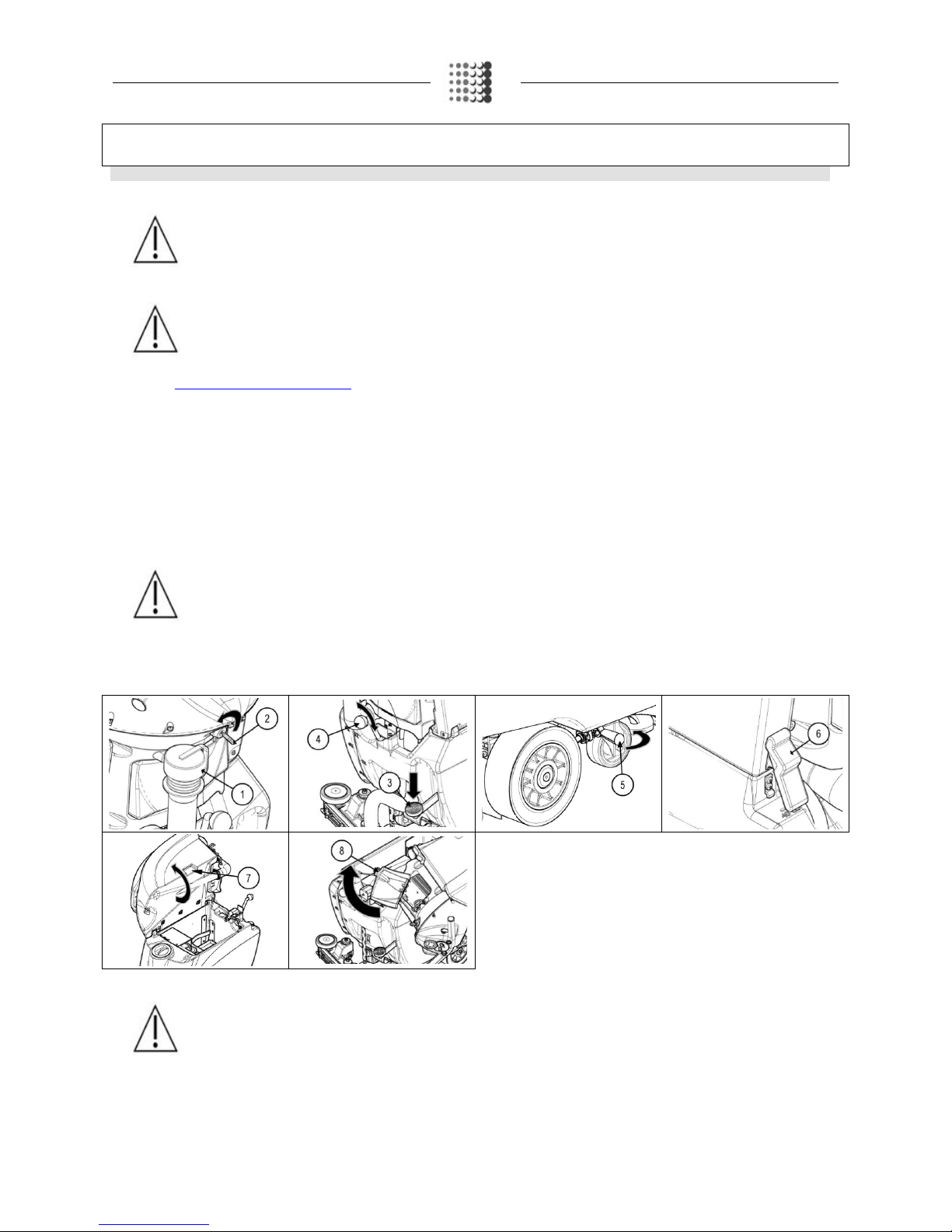
2. Check that the main switc h is in the “0” position; if t his is not the case, tur n the key (1) by a quarter of a turn to the l eft. Remov e the key f rom the
instrument panel.
3. Check that the brush head unit is raised from the floor; if necessary turn the pedal (2) at the bottom of the device anticlockwise.
4. Check that the squeegee body is raised from the floor; if necessary use the lever (3) at the rear of the device.
5. For BT versions, check that the parking brake is on. If this is not the case, rotate the lever (4) in the sense shown by the picture
6. Remove the recovery tank using the hinge (5).
7. Grip the handle (6) on the left-hand side of the recovery tank.
8. Lift the recovery tank until you reach the end position.
9. Disconnect the battery connector (7) from the connector of the general system (8).
Page 10

PREPARATION OF THE APPLIANCE
6. TYPE OF BATTERY
To power the device you can use:
•
lead tubular plate traction batteries with liquid electrolyte.
•
airtight traction batteries with gasrecombination gel technology or AGM.
OTHER TYPES CANNOT NOT BE USED
.
Every battery consists of DIN-type elements connected in series and supplying 12V power to the clamps. The battery compartment can house two 12V
batteries. For a good working performance, we suggest using 12 V sealed gel batteries.
7. BATTERY HOPPER MAINTENANCE AND DISPOSAL
For maintenance and recharging, respect the instructions provided by the battery manufacturer.
Special atten
tion must be paid to the choice of battery charger, which differs according to the battery type and capacity.
When the battery elements in the battery hopper are exhausted, the battery hopper needs to be disconnected by specialised and
trained staff, and lifted
and removed from the battery compartment using suitable lifting devices. BATTERY HOPPER BATTERY ELEMENTS ARE CLASSIFIED AS
DANGEROUS WASTE AND MUST BE CONSIGNED TO THE AUTHORISED BODIES FOR CORRECT DISPOSAL.
8. INSERTING BATTERIES INTO THE DEVICE
The
batteries must be housed in the special compartment beneath the recovery tank and should be handled using lifting equipment that is suitable in
terms of both weight and coupling system. The batteries must also comply with the requirements of the CEI 21
-5 Standard. The dimensions of the
battery compartment are: 355 x 337 x H=220 mm.
WARNING: For battery maintenance and daily recharging, you must carefully follow the instructions provided by the manufacturer
or retailer. All installation and maintenance operations must be carried out by specialised personnel.
ATTENTION: Before handling the batteries, ensure that you comply with accident prevention regulations applicable in the country
where you work or with DIN EN 50272-3 and DIN EN 50110-1 Standards.
WARNING: To prevent an accidental short circuit use insulated tools to connect the batteries, and do not place or drop metal
objects on the battery. Remove rings, watches and any clothing with metal parts that may come into contact with the battery
terminals.
To insert the batteries into the compartment, proceed as follows:
1. Take all necessary steps to ensure that the device is in a safe condition (see “MACHINE SAFETY”).
WARNING: Before installing the battery hopper, clean the battery compartment with a damp cloth. Check that the connectors on the
cables supplied are functioning correctly.
WARNING: Check that the characteristics of the battery hopper that you are looking to use are appropriate for the type of work to be
performed. Verify the charge state of each element of the battery hopper and the state of the contacts present on each of its
elements.
WARNING: You are advised to always wear protective gloves, to avoid the risk of serious injury to your hands.
ATTENTION
: Before inserting the batteries, lift the bottom and connect the traction connector (this step is only to be performed for
BT versions of the device). this process must be carried out by qualified personnel. An incorrect connection of the connector may
cause a malfunction of the device.
Page 11

PREPARATION OF THE APPLIANCE
2. House the batteries in the compartment, positioning the poles “+” and “-“ opposite each ot h er
3. Connect to the battery drop cable (1) to the "+" and "-" terminals, so as to create a 24V voltage at the terminals.
4. Connect the battery connector (2) to the general system connector (3).
ATTENTION: It is recommended that all installation and maintenance operations should be carried out by expert personnel, trained
by the dedicated technical service centre.
WARNING: you are advised to always wear protective gloves, to avoid the risk of serious injury to your hands.
5. Grip the handle on the recovery tank and turn until it reaches the work position.
9. BATTERY CHARGER CONNECTION (only for systems without CB)
In order not to cause permanent damage to individual battery elements, it is essential to avoid their
complete discharge by recharging them within a few
minutes from the "discharged battery" warning light being switched on.
ATTENTION: Never leave individual battery elements completely discharged, even if the machine is not in operation. Check the
battery charger is suitable for the batteries installed, in terms of both capacity and type.
To connect the battery charger you must:
1. Move the appliance to the designated battery charging area.
ATTENTION: Park the device in an area protected from the elements and with suitable ventilation, on a flat and level surface.
There must be no objects near the device that could either damage it, or be damaged through contact with it.
2. Take all necessary steps to ensure that the device is in a safe condition (see MACHINE SAFETY
’”).
ATTENTION: this process must be carried out by qualified personnel. An incorrect connection of the connector may cause a
malfunction of the device.
ATTENTION: Check that the battery charger used is suitable for the batteries in the device and set up for the batteries installed.
WARNING: Carefully read the use and maintenance instructions of the battery charger that is used for charging.
3. Connect the battery charger cable to the battery connector (2).
4. Connect the recently wired cable to the external battery charger.
WARNING: Keep the recovery tank open for the duration of the battery recharging cycle to allow gas fumes to escape.
WARNING: The room used to recharge the batteries must be adequately ventilated to prevent the accumulation of gases that leak
from batteries.
The coupling connector of the battery charger is supplied inside the bag containing this instruction booklet, and must be fitted to the battery charger
cables as shown in the instructions.
WARNING: Danger of gas exhalation and leakage of corrosive liquids.
WARNING: Danger of fire: do not go near with free flames
5. When the recharge cycle is complete, disconnect the battery charger supply cable from the battery charger.
6. Disconnect the battery charger connector from the battery connector (2).
7. Connect the battery connector (2) to the connector of the general system (3).
8. Grip the handle on the recovery tank and turn it until it reaches the work position.
Page 12
PREPARATION OF THE APPLIANCE
10. BATTERY CHARGER CONNECTION (only for systems with CB)
In order not to cause permanent damage to individual battery elements, it is essential to avoid their complete discharge by r
echarging them within a few
minutes from the "discharged battery" warning light being switched on.
ATTENTION: Never leave individual battery elements completely discharged, even if the appliance is not in operation. Check the
battery charger is suitable for the batteries installed, in terms of both capacity and type.
To connect the battery charger you must:
1. Move the appliance to the designated battery charging area.
ATTENTION: Park the device in an area protected from the elements and with suitable ventilation, on a flat and level surface.
There must be no objects near the device that could either damage it, or be damaged through contact with it.
2. Check that the recovery tank is empty; if not, empty it using the tube provided for this purpose (1) positioned at the rear of the device (read the
section "EMPTYING THE RECOVERY TANK").
3. Check that the main switch is in the “0” (2) position. If this is not the case, turn the key by a quarter of a turn to the left. Remove the key from the
instrument panel.
4. Check that the brush head unit is raised from the floor, if necessary turn the pedal (3) at the bottom of the device anticlockwise.
5. Check that the squeegee unit is raised from the floor; if necessary use the lever (4) at the rear of the device.
6. For BT versions, check that the parking brake is on. If this is not the case, rotate the lever (5) in the sense shown by the picture.
7. Remove the recovery tank using the hinge (6).
8. Grip the handle (7) on the rear left side of the recovery tank and turn the recovery tank until it reaches the end position.
9. Open the drawer by pressing on the handle (8) located on the rear of the appliance.
10. Connect the battery charger cable to the socket on the charger itself.
11. Plug the battery charger cable into the mains socket.
WARNING: Keep the recovery tank open for the duration of the battery recharging cycle to allow gas fumes to escape.
WARNING: The room used to recharge the batteries must be adequately ventilated to prevent the accumulation of gases that leak
from batteries.
WARNING: Carefully read the use and maintenance manual of the charger that is delivered inside the bag containing this instruction
booklet.
WARNING: Before inserting the charger power cable into the socket, verify that there is no condensate or other forms of liquids.
ATTENTION: If the device's electrical system is inadvertently powered, the "POWER PLUG" symbol will be displayed on the top left
side of the control display. No controls will be operational whilst the battery is being charged.
Page 13

PREPARATION OF THE APPLIANCE
12. When the recharge cycle is complete, disconnect the battery charger power supply cable from wall plug.
13. Disconnect the battery charger cable from the charger socket.
14. Close the drawer.
11. HOUR METER
The control display is on the rear of the appliance. The second screen that appears after it is switched on
shows the appliance's total usage time. The digits that precede the "." symbol identify hours, whilst the digit
that follow
s it indicates hour decimals (an hour decimal corresponds to six minutes). The flashing hourglass
symbol (1) indicates that the hour meter is counting the machine's operation time.
12. BATTERY CHARGE LEVEL INDICATOR
The control display is on the rear of the
appliance. The graphic symbol that identifies the charge level of
batteries appears at the bottom of the control display. The indicator consists of charge level indicators.
With the minimum remaining charge is reached, the graphic symbol (2) will start to
blink and will switch off
after a few seconds and then the symbol (3) will start to blink. Under these conditions, take the device to
the battery charge area.
ATTENTION: A few seconds after the battery charge level reaches the critical level (1),
the brush motor switches off automatically. With the remaining charge it is possible to
complete the drying process before starting the recharge.
ATTENTION: A few seconds after the battery charge level reaches the discharge level
(2), the vacuum motor switches off automatically. With the remaining charge, however,
it is still possible to take the appliance to its dedicated recharging area (BT versions).
13. FORWARD MOVEMENT AT WORK SPEED (only for BT system)
This appliance is equipped with electronic
traction control. To move the appliance, follow the steps detailed below:
1. Check that the potentiometer adjustment knob (1) is set to minimum; if this is the case, fully turn it anti-clockwise.
2. Turn the main machine switch (2) to "I"; turn the key by a quarter turn to the right.
3. Engage the dead man's levers (3) on the handlebars.
4. Adjust the desired forward speed by turning the knob (1) gradually to the right.
ATTENTION: The device will not start to move (either forward or backward) if the potentiometer adjustment knob (1) is set to
minimum.
ATTENTION: Forward speed can be increased by turning the potentiometer's knob (1) clockwise.
To reverse, proceed as follows:
1. Check that the brush head unit is raised from the floor, if necessary turn the pedal (4) at the bottom of the device anticlockwise.
2. Check that the squeegee unit is raised from the floor; if necessary action the lever (5) at the rear of the device.
3. Engage the dead man's levers (3) on the handlebars in order to start the appliance's' movement.
ATTENTION: The reverse speed is lower than the forward speed to comply with current health and safety standards. If the
potentiometer is adjusted while reversing, the adjustment of the forward speed will be automatically changed.
ATTENTION: It is impossible to reverse if the squeegee body touches the floor. In order to reverse, lift the squeegee body from the
floor using the relevant lever on the back of the appliance.
Page 14

PREPARATION OF THE APPLIANCE
14. FILLING THE SOLUTION TANK
Before
filling the solution tank, carry out the following steps:
1. Take the machine to the dedicated solution tank filling area.
2. Take all necessary steps to ensure that the device is in a safe condition (see “MACHINE SAFETY
”).
3. Grip the handle (1) on the rear left side of the recovery tank and turn the recovery tank until it reaches the work position.
4. Secure the recovery tank with the hinge (2).
5. Check that the solution tank discharge plug (3) has been tightened, if that is not the case, not turn it clockwise.
6. Unscrew the filler cap (4) and fill the solution tank using a rubber hose or bucket.
ATTENTION: Check that the filter (5) under the filler cap (4) is positioned correctly; this is to prevent impurities and dirt causing
malfunctions to the appliance's water system.
7. Fill with clean water, at a temperature not higher than 50°C and not lower than 10°C. The tank level can be checked using the level indicator (6) on
the left-hand side at the rear of the appliance.
15. DETERGENT SOLUTION (only for versions without FSS)
After filling the solution tank with clean water add the liquid detergent to the tank in the concentration and manner indicat
ed on the detergent
manufacturer's label. To prevent the formation of an excessi
ve amount of foam that could damage the vacuum motor, use the minimum percentage of
detergent required.
WARNING: Always use detergents whose manufacturer's label indicates their suitability for scrubbing machines. Do not use acid
or alkaline products or solvents without this indication.
WARNING:
Acid or alkaline detergents can be used with pH values between 4 and 10 and that do not contain: oxidising agents,
chlorine or bromine, formaldehyde, mineral solvents.
ATTENTION: always use low foam detergent. To avoid the production of foam, before starting to clean, put a minimum quantity of
anti-foam liquid into the recovery tank. Do not use pure acids.
ATTENTION: protective gloves should always be worn before handling detergents or acidic or alkaline solutions to avoid serious
injury to hands.
16. FILLING THE DETERGENT CANISTER (only for systems with FSS)
After
filling the solution tank with clean water, proceed as follows:
1. Take all necessary steps to ensure that the device is in a safe condition (see “MACHINE SAFETY”)
2. Remove the cap (1) of the detergent canister (2).
3. Remove the detergent canister (2) from the solution tank compartment.
4. Fill the canister with the desired detergent, as shown on the label supplied with the appliance.
ATTENTION: protective gloves should always be worn before handling detergents or acidic or alkaline solutions to avoid serious
injury to hands.
ATTENTION: always use low foam detergent. To avoid the production of foam, before starting to clean, put a minimum quantity of
anti-foam liquid into the recovery tank. Do not use pure acids.
ATTENTION: Always use detergents whose manufacturer's label indicates their suitability for scrubbing machines. Do not use acid
or alkaline products or solvents without this indication.
Page 15
PREPARATION OF THE APPLIANCE
5. Put the canister (2) back into the solution tank compartment.
6. Tighten the screw cap (1) properly to prevent liquid leakage during operation, and ensure that the detergent suction filter (3) is correctly positioned
at the bottom of the canister.
7. Grip the handle (4) on the rear left side of the recovery tank and turn the recovery tank until it reaches the work position.
8. Secure the recovery tank with the hinge (5).
9. Before starting to use the appliance for the first time, carefully read the paragraphs “REGULATING THE DETERGENT (only for FSS systems)
”
and “TRIGGERING THE DOSING SYSTEM (only for FSS systems)”.
WARNING: The dosing system is suitable for frequent maintenance cleaning. Acid or alkaline detergents can be used with pH
values between 4 and 10 and that do not contain: oxidising agents, chlorine or bromine, formaldehyde, mineral solvents. The
detergents used must be suitable for use with scrubbing machines. Wash the circuit with water after use if the system is not used
daily. The system can be excluded. In case of sporadic use of detergents with pH between 1-3 or 11-14, use the floor scrubbing
machine in the traditional way by adding the detergent in the clean water tank and excluding the dosing circuit.
17. ASSEMBLING THE SQUEEGEE
For packaging reasons, the squeegee is supplied disassembled from the device, and must be assembled as follows:
1. Take all necessary steps to ensure that the device is in a safe condition (see “MACHINE SAFETY”)
2. Grip the handle (1) on the rear left side of the recovery tank and turn the recovery tank until it reaches the work position.
3. Secure the recovery tank with the hinge (2).
4. Loosen the knobs (3) in the squeegee body pre-assembly.
5. First insert the left-hand squeegee pin on the squeegee body into the left-hand slit (4) of the squeegee connection, then tighten the knob (3),
making sure that the washer (5) and spring adhere to the upper part of the squeegee support.
6. Insert the right-hand squeegee pin on the squeegee body into the right-hand slit (6) of the squeegee connection, then tighten the knob (3),
making sure the washer (7) and spring adhere to the upper part of the squeegee support.
7. Tighten the handwheel (3) to lock the squeegee into place.
8. Finally, insert the vacuum hose (8) of the squeegee into the relative joint (9) of the vacuum nozzle.
WARNING: The squeegee has already been regulated, however if it needs adjusting, read the section “REGULATING THE
SQUEEGEE”.
ATTENTION: these operations must be carried out using protective gloves to avoid any possible contact with the edges or tips of
metal objects.
Page 16

PREPARATION OF THE APPLIANCE
18. BRUSH ASSEMBLY (only for single-disc versions)
For packaging reasons, the brush is supplied disassembled from the device, and must be assembled as follows:
1. Take all necessary steps to ensure that the device is in a safe condition (see “MACHINE SAFETY”).
2. Grip the handle (1) on the rear left side of the recovery tank and turn the recovery tank until it reaches the work position.
3. Secure the recovery tank with the hinge (2).
4. With the brush head detached from the floor, place the brush into the body underneath the brush head.
5. Lower the brush head unit positi oni ng it onto the brush by activating the brush head unit control pedal (3).
6. Rotate the brush until the coupling system in the brush plate locks with the brush locking system (for MMx 43 versions).
7. Rotate the brush until the three buttons in the brush enter into the notches in the brush plate (for MMx 50 versions).
8. To lock, click them into position by turning them anticlockwise to the direction of travel.
9. For the MMx 43 version, reassemble the brush head splash guard (read the paragraph“BRUSH HEAD SPLASH GUARD ASSEMBLY
”).
WARNING: you are advised to always wear protective gloves, to avoid the risk of serious injury to your hands.
19. BRUSH ASSEMBLY (only for twin-disc versions)
For packaging reasons, brushes are supplied disassembled from the appliance, and must be assembled as follows:
1. Take all necessary steps to ensure that the device is in a safe condition (see “MACHINE SAFETY”)
2. Grip the handle (1) on the rear left side of the recovery tank and turn the recovery tank until it reaches the work position.
3. Secure the recovery tank with the hinge (2).
4. With the brush head detached from the floor, place the brush into the body underneath the brush head.
5. Lower the brush head unit, positioning it onto the brushes by activating the brush head unit control pedal (3).
6. Rotate the brush unit the brush's three buttons grip with the notches in the brush plate.
7. To lock, click them into position by turning them anticlockwise to the direction of travel for the right-hand brush and clockwise for the left-hand
brush.
8. Reassemble the brush head splash guard (read the paragraph“BRUSH HEAD SPLASH GUARD ASSEMBLY
”).
WARNING: you are advised to always wear protective gloves, to avoid the risk of serious injury to your hands.
Page 17

PREPARATION OF THE APPLIANCE
20. ASSEMBLING THE SPLASH GUARD
For packaging reasons, the brush head splash guard is supplied disassembled from the device, and must be assembled as follows
:
1. Take all necessary steps to ensure that the device is in a safe condition (see “MACHINE SAFETY”).
2. Grip the handle (1) on the rear left side of the recovery tank and turn the recovery tank until it reaches the work position.
3. Secure the recovery tank with the hinge (2).
4. Lower the brush head unit positioning it onto the brushes by activating the brush head unit control pedal (3).
5. Unhook the spring hook (4) from the fastening screw on the right-hand side of the brush head (direction of work).
6. Remove the fixing strip (5) of the rubber splash guard.
7. Wind the rubber splash guard (6) around the brush head, positioning it is such a way so as it is symmetrical to the brush, after first inserting it into
the pin (7) located on the brush head's left-hand side (work direction).
8. Reposition the previously removed strip (5) and insert it into the pin (7) on the left-hand side of the brush head (work direction).
9. Unhook the spring's hook (4) from the fastening screw (8) on the right-hand side of the brush head (direction of work).
WARNING: you are advised to always wear protective gloves, to avoid the risk of serious injury to your hands.
ATTENTION: For the twin-disc version, repeat the operation for both strips.
Page 18

PREPARING TO WORK
1. PREPARING TO WORK
Before beginning to work, it is necessary to:
1. Make sure the recovery tank is empty, otherwise empty it completely (read “EMPTYING THE RECOVERY TANK
”).
2. Check that the vacuum motor filter has been correctly cleaned; if this is not the case, clean it (read the paragraph “CLEANING THE VACUUM MOTOR
FILTER FLOAT”).
3. Check that the solution tank filter has been correctly cleaned; if this is not the case, clean it (read the paragraph “CLEANING THE SOLUTION TANK
FILTER””).
4. Verify that the quantity of detergent solution in the solution tank is suitable for the type of work you wish to carry out, otherwise fill the solution tank (see
the paragraph “FILLING THE SOLUTION TANK
”). Check the level tube (1) on the rear left-hand side of the appliance.
5. Check that the state of the squeegee rubbers are suitable for work, if not have them maintained (read the sections “CLEANING THE SQUEEGEE
BODY” or “REPLACING THE SQUEEGEE RUBBER”). Check that the squeegee’s vacuum chamber and the relevant suction inlet have been properly
cleaned (read paragraphs“CLEANING THE SQUEEGEE BODY”).
6. Check that the condition of brushes is suitable for the work to be performed, otherwise arrange for their maintenance (see paragraph “BRUSH
CLEANING” or “CENTRAL BRUSH REPLACEMENT”).
7. Free the recovery tank using the hinge (2).
8. Grip the handle (3) on the rear left side of the recovery tank (work direction) and turn the recovery tank until it reaches the end position.
9. Check that the battery (4) is connected to general system connector (5); if not, connect them together.
10. Check that the amount of detergent in the canister (4) is suitable for the type of work you wish to carry out, if not, fill up with detergent (read the section
“FILLING THE DETERGENT CANISTER (only for FSS versions)
”).
11. Grip the handle (3) on the rear left side of the recovery tank (work direction) and turn the recovery tank until it reaches the work position.
12. Secure the recovery tank with the hinge (2).
13. For BT versions, check that the parking brake is not on. If this is not the case, rotate the lever (6) in the sense shown by the pict ure.
2. TRIGGERING THE DOSING SYSTEM (only for FSS system)
Before starting to work for the first time, or after a long period of appliance inactivity, it is necessary to proceed as follows:
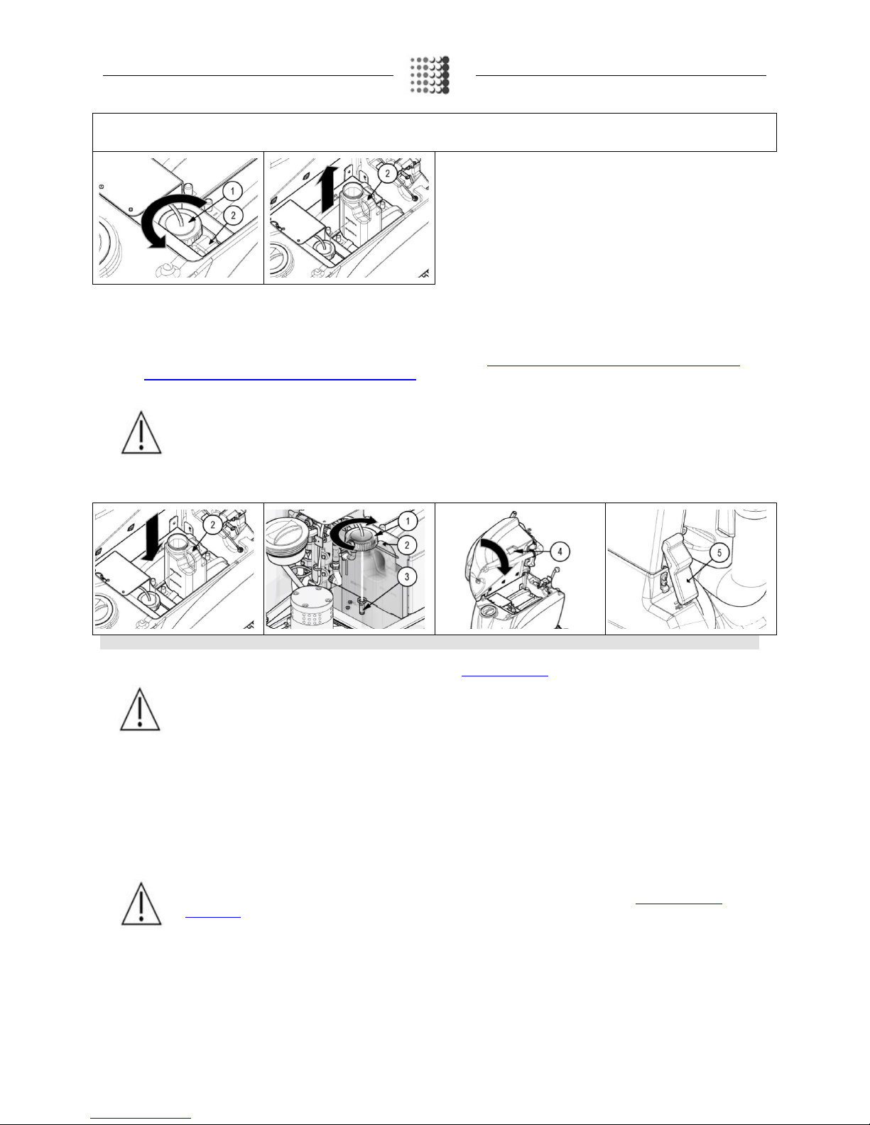
1. Check that the water tap is fully turned on, turn the knob (1) to the left.
2. Check that the detergent solution tap (on the brush head unit) is in the active dosing system position; the lever (2) must be in a vertical position.
3. Turn the main machine switch to "I", turn the key (3) a quarter rotation to the right.
4. When the control display shows the work screen, turn the water flow knob (4) to the right, to the maximum flow position.
Page 19

PREPARING TO WORK
5. Turn the detergent flow adjustment knob (5) to the left, to the maximum flow position.
6. Lower the brush head unit by actioning the pedal (6) located on the rear of the appliance.
7. Lower the brush head unit using the lever (7) on the rear of the appliance.
8. Action the dead man's levers (8) under the control handlebar, to allow activation of the appliance and the dosing system.
9. Wait a few moments keeping the dead man's levers pressed (normally 40 to 60 seconds) to allow the dosing system to be triggered.
Page 20

WORK
1. STARTING WORK
To start working, proceed as follows:
1.
Carry out all the checks in the chapter “PREPARING TO WORK”.
2.
Turn the main machine switch to "I", turn the key (1) a quarter rotation to the right. The control display on the control panel will immediately comes
on.
3.
Lower the brush head unit by pressing the pedal (2) located on the rear of the appliance.
4.
Lower the brush head unit using the lever (3) on the rear of the appliance.
5.
By pressing the dead man's levers (4) under the control handlebar, the appliance will start to operate in full efficiency conditions up until the
detergent solution is depleted or the batteries are discharged.
ATTENTION: For BT versions, adjust forward speed (read the paragraph“
WORKING FORWARD SPEED (only for systems without
BT)”.
ATTENTION: When filling the solution tank, it is good practice to empty the recovery tank using the special drainage hose.
2. DETERGENT ADJUSTMENT (only for versions without FSS)
To regulate the amount of detergent solution on the brushes, proceed
as follows:
1. Fully open the tap on the rear of the appliance by rotating the knob (1) on the rear of the device downwards.
2. By using the dead man's levers (2) both the brush motor and the vacuum motor will kick in and the solenoid valve will distribute the detergent
solution to the brushes.
3. During the first few meters, check that the quantity of solution is enough to wet the floor, but not so much as to come out of the splash guard; the
detergent disposal quantity can be adjusted by means of the knob (1) on the appliance's rear.
ATTENTION: In the event of malfunction of the water system, read the paragraph “CLEANING THE SOLUTION TANK FILTER”.
3. DETERGENT ADJUSTMENT (only for versions with FSS)
To regulate
the amount of detergent solution on the brushes, proceed as follows:
1. Fully open the flow coming from the tap on the rear of the appliance by turning the lever (1) on the appliance's rear downwards.
2. By actioning the dead man's levers (2) both the brush motor and the vacuum motor will kick in and the solenoid valve will distribute detergent
solution to the brushes.
3. During the first few meters, check that the quantity of solution is enough to wet the floor, but not so much as to come out of the splash guard; the
flow of detergent can be adjusted using the water flow adjustment knob (3) and the detergent flow adjustment knob (4) on the appliance's control
panel.
ATTENTION: The quantity of water varies from a minimum of 30 litres/hour to a maximum of 70 litres/hour, with 7 dosing levels.
The correct water flow must be selected depending on the type of flooring and must be proportional to the flooring's dirt conditions
and forward speed. In addition, remember that the time available for continuous operation depends on the quantity of water in the
tank
Page 21

WORK
WARNING: The percentage of detergent in the solution varies from a minimum of 0.5 % to a maximum of 3.5 % with 7 set dosing
levels. The correct flow of detergent should depend on the nature of the floor; it must be proportional to the intensity of dirt on the
floor and the forward movement speed. In addition, remember that the time available for continuous working depends on the
quantity of water in the tank.
ATTENTION: If the detergent solution supply pump does not work (only for version with FSS) read the paragraph “BYPASSING
THE WATER SYSTEM SUPPLY PUMP (only for version with FSS)”
ATTENTION: In the event of water system malfunction, read the paragraph “CLEANING THE SOLUTION TANK FILTER”
or“CLEANING THE WATER SYSTEM FILTER (only for MMx 50 versions)”.
4. "ECO MODE" DEVICE
By activating the “ECO
-MODE” function using the relevant button (1) on the control panel, the energy used by the appliance is reduced, decreasing the
power of the brush motor and the vacuum motor. When the ECO
-MODE program is activated, the wording "ECO" is displayed on the control display.
Th
e cancel the ECO-MODE program, just press the button again. The ECO-MODE function can only be activated during the washing and scrubbing
phase (with brush head unit and squeegee head unit touching the floor) or during the drying phase (with brush head unit
lifted and squeegee head unit
touching the floor).
ATTENTION: Should the squeegee head unit be lifted in ECO-MODE mode, the vacuum mode would revert to "STANDARD"
mode and continue to operate for a period of time, to then switch off automatically.
5. OVERFLOW DEVICE
The appliance is equipped with a mechanical device (float) under the recovery tank cap that, when the recovery tank is full,
shuts off the air to the
vacuum motor intake to protect it; the sound of the vacuum motor will then be
deeper. If this is the case, proceed as follows:
1. Lift the brush head unit by using the pedal located on the appliance's rear.
2. Lift the squeegee body using the lever on the appliance's rear.
3. Take the appliance to the designated waste water drainage area and empty the recovery tank (read the paragraph “
EMPTYING THE RECOVERY
TANK” carefully first).
Page 22

AT THE END OF THE WORK
At the end of the work, and before carrying out any type of maintenance, perform the following operations:
1. Take the appliance to the dedicated maintenance area and perform all operations described in the chapter "DAILY MAINTENANCE".
2. Take the appliance to the designated storage area.
WARNING: Park the appliance in an enclosed place, on a flat surface; near the appliance there must be no objects that could either
damage it, or be damaged through contact with it.
3. Perform all the procedures listed in the paragraph“ENSURING APPLIANCE SAFETY
”.
4. Grip the handle (1) on the rear left side of the recovery tank and turn the recovery tank until it reaches the work position.
5. Secure the recovery tank with the hinge (2).
ATTENTION: At the end of the work, it is advised to turn the recovery tank cap to the maintenance position to prevent bad odours.
Page 23

DAILY MAINTENANCE
PERFORM ALL MAINTENANCE OPERATIONS IN SEQUENCE
1. EMPTYING THE RECOVERY TANK
Proceed as follows to empty the recovery
tank:
1. Take the appliance to the dedicated waste water drainage area.
2. Take all necessary steps to ensure that the device is in a safe condition (see “MACHINE SAFETY
”)
3. Grip the handle (1) on the rear left side of the recovery tank (work direction) and turn the recovery tank until it reaches the work position.
4. Secure the recovery tank with the hinge (2).
5. Remove the drainage hose (3) of the recovery tank from the clamps; it is located at the rear of the device.
6. Bend the end of the drainage tube, so as to create a choke and prevent the content from coming out, put the tube on the discharge surface and
gradually release the tube.
7. Repeat the operations in reverse order to reassemble all the parts.
WARNING: You are advised to always wear protective gloves, to avoid the risk of serious injury to your hands.
WARNING: The place this operation is carried out should comply with current environmental protection regulations.
2. EMPTYING OF THE SOLUTION TANK
Proceed as
follows to empty the solution tank:
1. Take the appliance to the dedicated waste water draining area.
2. Take all necessary steps to ensure that the device is in a safe condition (see “MACHINE SAFETY
”)
3. Grip the handle (1) on the rear left side of the recovery tank (work direction) and turn the recovery tank until it reaches the work position.
4. Secure the recovery tank with the hinge (2).
5. Close the flow coming from the tap on the rear of the appliance by turning the knob (3) on the rear of the appliance downwards.
6. Unscrew the solution tank lid (4) located on the rear of the appliance.
7. Repeat the operations in reverse order to reassemble all the parts.
WARNING: You are advised to always wear protective gloves, to avoid the risk of serious injury to your hands.
WARNING: The place this operation is carried out should comply with current environmental protection regulations.
3. CLEANING THE SQUEEGEE BODY
The careful cleaning of the whole vacuum unit ensures better drying
and cleaning of the floor as well as a longer vacuum motor life. To clean the
squeegee unit, proceed as follows:
1. Take the device to the dedicated maintenance area.
2. Take all necessary steps to ensure that the device is in a safe condition (see “MACHINE SAFETY
”)
3. Grip the handle (1) on the rear left side of the recovery tank (work direction) and turn the recovery tank until it reaches the work position.
4. Secure the recovery tank with the hinge (2).
5. Remove the vacuum hose (3) from the vacuum nozzle (4) on the squeegee body.
6. Loosen the knobs (5) in the squeegee body pre-assembly.
7. Remove the squeegee body from the slits in the squeegee connector.
8. First with a jet of water and then with a damp cloth, thoroughly clean the vacuum chamber (6) of the squeegee unit.
Page 24

DAILY MAINTENANCE
WARNING: You are advised to always wear protective gloves, to avoid the risk of serious injury to your hands.
WARNING: The place this operation is carried out should comply with current environmental protection regulations.
9. First with a jet of water and then with a damp cloth, thoroughly clean the front rubber blade (7) of the squeegee body.
10. Check the wear of the front rubber blade (7) on the squeegee body; if the edge of the rubber that is in contact with the floor is worn replace it,
reading the paragraph "REPLACING THE SQUEEGEE UNIT RUBBER BLADES
".
11. First with a jet of water and then with a damp cloth, thoroughly clean the rear rubber blade (8) of the squeegee body.
12. Check the wear of the rear rubber blade (8) on the squeegee body; if the edge of the rubber that is contact with the floor is worn, replace it,
reading the paragraph "REPLACING THE SQUEEGEE RUBBER BLADES
" first; in any event it is possible to turn the rubber blade around four
edges.
13. Tighten the knobs (9) that fix the vacuum nozzle (4) to the squeegee body.
14. First with a jet of water and then with a damp cloth, thoroughly clean the vacuum nozzle (4). Also clean the squeegee body support surface.
15. Repeat the operations in reverse order to reassemble all the parts.
4. CLEANING THE BRUSH
Careful cleaning of the brush guarantees better cleaning of the floor as
well as a longer brush motor life. To clean the brush, proceed as follows:
1. Take the device to the dedicated maintenance area.
2. Take all necessary steps to ensure that the device is in a safe condition (see “MACHINE SAFETY
”)
3. Grip the handle (1) on the rear left side of the recovery tank (work direction) and turn the recovery tank until it reaches the work position.
4. Secure the recovery tank with the hinge (2).
5. Press the brush release button (3) on the control panel. As soon as the button is pressed, the letter "S" will be displayed on the work screen. Press
the brush release button (3) again to confirm (applies to single-disc versions only). For twin-disc machines, rotate individual brushes manually
until they are dislodged from their housing in the brush plate.
6. Clean the brush under running water to remove any impurities from its bristles. Check that the bristles are not worn; in the event of excessive wear
replace the brush (the bristles should be at least 10 mm long). Read the paragraph "REPLACING THE BRUSH
" to replace the brush.
7. Repeat the operations in reverse order to reassemble all the parts.
WARNING: You are advised to always wear protective gloves, to avoid the risk of serious injury to your hands.
WARNING: The place this operation is carried out should comply with current environmental protection regulations.
ATTENTION: For twin-disc versions it is recommended to switch the right and left brush on a daily basis and vice-versa. If the
brushes are not new however, and have deformed bristles, it is better to reassemble them in the same position (the right-hand one on
the right, and the left-hand one on the left), to prevent the different inclination of the bristles producing an overload on the brush motor
as well as excessive vibrations.
Page 25

DAILY MAINTENANCE
5. CLEANING THE VACUUM MOTOR FILTER FLOAT
Careful cleaning of the recovery tank filter guarantees better cleaning of the floor as well as a longer vacuum
motor life. Proceed as follows to clean the
recovery tank filter:
1. Take the device to the dedicated maintenance area.
2. Take all necessary steps to ensure that the device is in a safe condition (see “MACHINE SAFETY
”)
3. Grip the handle (1) on the rear left side of the recovery tank (work direction) and turn the recovery tank until it reaches the work position.
4. Secure the recovery tank with the hinge (2).
5. Grip the handle (3) on the front side of the vacuum cap, rotate the vacuum cap until the hook (4) is secured to the recovery tank's prop (5).
6. Remove the vacuum filter protection (6) by rotating it in a clockwise direction. Release the retaining clips (7). Take the vacuum filter out of the
housing (8), clean the walls and the bottom of the filter with a jet of water, remove any dirt that is attached.
7. Repeat the operations in reverse order to reassemble all the parts.
WARNING: You are advised to always wear protective gloves, to avoid the risk of serious injury to your hands.
WARNING: The place this operation is carried out should comply with current environmental protection regulations.
6. CLEANING THE SOLUTION TANK FILTER
The careful cleaning of the solution tank filter guarantees a longer life span of the
appliance's water circuit system, ensuring a better floor cleaning
performance. Proceed as follows to clean the solution tank's filter:
1. Take the device to the dedicated maintenance area.
2. Take all necessary steps to ensure that the device is in a safe condition (see “MACHINE SAFETY
”)
3. Grip the handle (1) on the rear left side of the recovery tank (work direction) and turn the recovery tank until it reaches the work position.
4. Secure the recovery tank with the hinge (2).
5. Loosen the drain cap (3) and clean it with clean running water; where needed, remove any impurities from it.
6. Repeat the operations in reverse order to reassemble all the parts.
WARNING: You are advised to always wear protective gloves, to avoid the risk of serious injury to your hands.
WARNING: The place this operation is carried out should comply with current environmental protection regulations.
Page 26

WEEKLY MAINTENANCE
1. CLEANING THE RECOVERY TANK
The careful cleaning of the recovery tank
guarantees a longer appliance life span. Proceed as follows to clean the recovery tank:
1. Take the device to the dedicated maintenance area.
2. Take all necessary steps to ensure that the device is in a safe condition (see “MACHINE SAFETY
”).
3. Grip the handle (1) on the rear left side of the recovery tank (work direction) and turn the recovery tank until it reaches the work position.
4. Secure the recovery tank with the hinge (2).
5. Remove the recovery tank's drainage hose (3) from the clamps, located at the rear of the appliance; unscrew the cap and place it on the ground.
6. Grip the handle (4) on the front side of the vacuum cap, rotate the vacuum cap until the hook (5) is secured to the recovery tank's prop (6).
7. Rinse the inside with a jet of water, if necessary use a spatula to remove the sludge that has accumulated at the bottom of the tank.
8. Repeat the operations in reverse order to reassemble all the parts.
WARNING: You are advised to always wear protective gloves, to avoid the risk of serious injury to your hands.
WARNING: The place this operation is carried out should comply with current environmental protection regulations.
2. CLEANING THE SOLUTION TANK
The careful cleaning of the solution tank guarantees a longer
appliance life span. Proceed as follows to clean the solution tank:
1. Take the device to the dedicated maintenance area.
2. Take all necessary steps to ensure that the device is in a safe condition (see “MACHINE SAFETY
”)
3. Grip the handle (1) on the rear left side of the recovery tank (work direction) and turn the recovery tank until it reaches the work position.
4. Secure the recovery tank with the hinge (2).
5. Check that the detergent solution tap is off; rotate the lever (3) on the rear of the appliance to the right (work direction).
6. Loosen the solution tank cap (4) and clean it with clean running water; where needed, remove any impurities from it.
7. Remove the filling cap (5) and the filter (6) on the front of the appliance. Clean the filter (6) with a jet of water and remove any dirt.
8. Rinse the inside of the solution tank with a jet of water.
9. Repeat the operations in reverse order to reassemble all the parts.
WARNING: You are advised to always wear protective gloves, to avoid the risk of serious injury to your hands.
WARNING: The place this operation is carried out should comply with current environmental protection regulations.
Page 27

WEEKLY MAINTENANCE
3. CLEANING THE VACUUM HOSE
Careful cleaning of the vacuum hose
guarantees better cleaning of the floor as well as a longer vacuum motor life. Proceed as follows to clean the
vacuum hose:
1. Take the device to the dedicated maintenance area.
2. Take all necessary steps to ensure that the device is in a safe condition (see “MACHINE SAFETY
”).
3. Grip the handle (1) on the rear left side of the recovery tank (work direction) and turn the recovery tank until it reaches the work position.
4. Secure the recovery tank with the hinge (2).
5. Remove the vacuum hose (3) from the vacuum nozzle (4) on the squeegee body.
6. Grip the handle (5) on the front side of the vacuum cap, rotate the cap (6) until the hook (7) is secured to the recovery tank's prop (8).
7. Clean the inside with a jet of water, inserting the hose in the part of the vacuum nozzle (8) fixed to the recovery tank.
8. Repeat the operations in reverse order to reassemble all the parts.
WARNING: You are advised to always wear protective gloves, to avoid the risk of serious injury to your hands.
WARNING: The place this operation is carried out should comply with current environmental protection regulations.
4. CLEANING THE DETERGENT CANISTER (only for system with FSS)
Careful cleaning of the detergent canister ensures improved floor cleaning performance as well as a longer water circuit system life span. To clean the
canister, proceed as follows:
1. Take all necessary steps to ensure that the device is in a safe condition (see “MACHINE SAFETY
”).
2. Remove the cap (1) of the detergent canister (2).
3. Remove the detergent canister (2) from the solution tank compartment.
4. Rinse the inside of the canister with a jet of running water.
5. Repeat the operations in reverse order to reassemble all the parts.
WARNING: The place this operation is carried out should comply with current environmental protection regulations.
WARNING: Do not throw the detergent directly into the drain, but comply with current environmental protection regulations.
ATTENTION: Screw on the cap (1) of the detergent canister (2), making sure that the detergent suction filter (3) is correctly
positioned on the bottom of the canister.
Page 28

EXTRAORDINARY MAINTENANCE
1. REPLACING THE SQUEEGEE RUBBERS
The good condition of the squeegee rubber ensures
improved drying and cleaning of the floor, as well as a longer vacuum motor life. To replace the
squeegee rubber, proceed as follows:
1. Take the device to the dedicated maintenance area.
2. Take all necessary steps to ensure that the device is in a safe condition (see “MACHINE SAFETY
”).
3. Grip the handle (1) on the rear left side of the recovery tank (work direction) and turn the recovery tank until it reaches the work position.
4. Secure the recovery tank with the hinge (2).
5. Remove the vacuum hose (3) from the vacuum nozzle (4) on the squeegee body.
6. Fully loosen the knobs (5) in the squeegee body pre-assembly.
7. Remove the squeegee body from the slits in the squeegee connector.
WARNING: you are advised to always wear protective gloves, to avoid the risk of serious injury to your hands.
Proceed as follows for replacing the front rubber blade of the squeegee body:
1. Turn the wing nuts (6) in the horizontal position.
2. Remove the front rubber-pressing blades (7).
3. Remove the rubber (8) and replace it.
4. Proceed in reverse to replace the rubber.
Proceed as follows for replacing the rear rubber blade of the squeegee body:
1. Turn the wing nuts (9) in the horizontal position.
2. Remove the rear rubber-pressing blades (10).
3. Remove the rubber (11) and replace it or turn it over.
4. Proceed in reverse to replace the rubber.
Page 29

EXTRAORDINARY MAINTENANCE
2. ADJUSTING THE SQUEEGEE
Careful adjustment of the height between the squeegee rubber and the floor guarantees better
drying and cleaning of the flooring as well as a longer
vacuum motor life. To adjust the squeegee rubber, proceed as follows:
1. Take the device to the dedicated maintenance area.
2. Turn the main machine switch to "I", turn the key (1) a quarter turn to the right.
3. Lower the brush head unit by actioning the pedal (2) located on the rear of the appliance.
4. Lower the brush head unit using the lever (3) on the rear of the appliance.
5. Adjust the detergent solution flow (read the paragraphs "REGULATING THE DETERGENT (only for systems without FSS)” or “
REGULATING
THE DETERGENT (only for systems with FSS)”)
6. By pressing the dead man's levers (4) under the control handlebar, the appliance will start to operate.
If you need to increase the inclination of the rubber blade in the centre, it is necessary to tighten the screw (5), while to decrease it just turn the screw
(5) in the opposite
direction. During working operation, the rear rubber blade should be slightly tilted backwards by about 30°- 45° with respect to the
floor in a uniform way along its whole length. This means that the height of the squeegee should be regulated, and this is
done by turning the knob (6)
(in the diagram only the right knob is depicted) anti
-clockwise to raise the squeegee and in the opposite direction to lower it.
ATTENTION: The right and left wheels must be adjusted to the same level, so the squeegee can work parallel to the floor.
3. REPLACING THE BRUSH
The brush's integrity ensures better floor cleaning, as well as a longer brush motor life span. To replace the brush, proceed
as follows:
1. Take the device to the dedicated maintenance area.
2. Take all necessary steps to ensure that the device is in a safe condition see “MACHINE SAFETY
”).
3. Grip the handle (1) on the rear left side of the recovery tank (work direction) and turn the recovery tank until it reaches the work position.
4. Secure the recovery tank with the hinge (2).
5. Press the brush release button (3) on the control panel. As soon as the button is pressed, you the letter "RELEASE" will be displayed on the work
screen. Press the brush release button (3) again to confirm (applies to single-disc machines only). For twin-disc machines, rotate the individual
brush manually until it is dislodged from its housing in the brush plate.
6. Replace the old brush with a new one (read paragraph“ASSEMBLING THE BRUSH (only for single-disc versions)” or “ASSEMBLING THE BRUSH
(only for twin-disc versions)”).
WARNING: you are advised to always wear protective gloves, to avoid the risk of serious injury to your hands.
Page 30

EXTRAORDINARY MAINTENANCE
4. REPLACING THE BRUSH HEAD SPLASH GUARD
The brush head splash guard's integrity ensures better floor cleaning performance, as well as a longer brush motor life
span. To replace the brush head
splash guard, proceed as follows:
1. Take all necessary steps to ensure that the device is in a safe condition (see “MACHINE SAFETY”).
2. Grip the handle (1) on the rear left side of the recovery tank and turn the recovery tank until it reaches the work position.
3. Secure the recovery tank with the hinge (2).
4. Lower the brush head unit positioning it onto the brushes by activating the brush head unit control pedal (3).
5. Unhook the hook (4) of the spring from the fastening screw on the right-hand side of the brush head (direction of work).
6. Remove the fixing strip (5) of the rubber splash guard.
7. Replace the old splash guard with the new one (read paragraph "ASSEMBLING THE BRUSH HEAD SPLASH GUARD
").
WARNING: you are advised to always wear protective gloves, to avoid the risk of serious injury to your hands.
5. RINSING THE DOSING SYSTEM (only for FSS system)
If the appliance is not used for long periods of time (more than 48 hours), it is recommended that the dosing system should be rinsed. To do this,
proceed as follows:
1. Take the device to the dedicated maintenance area.
2. Take all necessary steps to ensure that the device is in a safe condition (see “MACHINE SAFETY
”).
3. Remove the cap (1) of the detergent canister (2).
4. Remove the detergent canister (2) from the solution tank compartment.
5. Remove any detergent residue. Rinse the inside of the canister with a jet of running water. Fill the canister with clean water
6. Tighten the screw cap (1) properly to prevent liquid from leaking during operation, and ensure that the detergent suction filter (3) is correctly
positioned at the bottom of the canister.
7. Put the canister (2) back into the solution tank compartment.
WARNING: The place this operation is carried out should comply with current environmental protection regulations.
WARNING: Do not throw the detergent directly into the drain, but comply with current environmental protection regulations.
WARNING: You are advised to always wear protective gloves, to avoid the risk of serious injury to your hands.
Page 31

EXTRAORDINARY MAINTENANCE
8. Connect the battery connector (4) to the general system connector (5).
9. Grip the handle (6) on the rear left side of the recovery tank and turn the recovery tank until it reaches the work position.
10. Secure the recovery tank with the hinge (7).
11. Make sure the solution tank is full, if not,fill it up (read the section "FILLING THE SOLUTION TANK WITH WATER"). Check the level indicator (8)
on the rear left-hand side of the appliance.
12. Check that the water tap is fully turned on, turn the knob (9) to the left.
13. Check that the detergent solution tap (on the brush head unit) is in the active dosing system position; the lever (10) must be in a vertical position.
14. Turn the main machine switch to "I", turn the key (11) a quarter rotation to the right.
15. When the control display shows the working screen, turn the water flow knob (12) to the right, to the maximum flow position.
16. Turn the detergent flow adjustment knob (13) to the left, to the maximum flow position.
17. Lower the brush head unit by pressing the pedal (14) located on the rear of the appliance.
18. Lower the brush head unit using the lever (15) on the rear of the appliance.
19. Action the dead man's levers (16) under the control handlebar, to allow activation of the appliance and the dosing system.
20. Wait a few moments keeping the dead man's levers pressed (normally 40 to 60 seconds) to allow the dosing system to be triggered.
Page 32

TROUBLESHOOTING
1. AN ALARM MESSAGE APPEARS ON THE CONTROL DISPLAY
If, when starting or using the appliance, a warning message appears on the control display, stop the appliance immediately and contact the technician
at the dedicated Technical Service Centre.
2. THE APPLIANCE DOES NOT SWITCH ON
1. Check that the main switch is in the "I" position; if this is not the case, turn the key (1) by a quarter of a turn to the right.
2. Make sure that, when starting the machine, NO alarm message appears on the control display; read the paragraph “
AN ALARM MESSAGE
APPEARS ON THE CONTROL DISPLAY”.
3. Check that the battery (2) is connected to general system connector (3); if not, connect them together.
4. Check the battery charge level, check the symbol on the control display. If the charge level of batteries is critical, go through a full charge cycle
(read the paragraph“CONNECTING BATTERIES (only for systems without battery charger)” or “
CONNECTING BATTERY CHARGER (only for
systems with battery charger)”).
WARNING: If all these procedures do not solve the problem, contact the technician at the dedicated Technical Service Centre.
3. THE BATTERIES ARE NOT CHARGED CORRECTLY
1. Check that the battery (1) is connected to general system connector (2); if not, connect them together.
2. Check that the battery charger used is suitable for the batteries in the appliance and is correctly set up for the batteries used.
3. Referring to the battery c harger use and m aintenance manual, chec k the meaning of t he flashing si gnals that the b attery charg er emits dung th e
battery recharge stage.
WARNING: If all these procedures do not solve the problem, contact the technician at the specialist technical assistance centre.
4. THE DEVICE HAS A VERY LOW OPERATING AUTONOMY
1. Check that there is water in the solution tank; the level in the tank checked using a level indicator (1) on the left rear of the device.
2. Check the battery charge leve l, check the symbol on the contr ol display. If the charge lev el of batteries is crit ical, go through a full charge cyc le
(read the paragraph“CONNEC TING BATTERIES (only for systems w ithout battery charger)” or“
CONNECTING BATTERY CHARGER (only for
systems with battery charger)”).
Page 33

TROUBLESHOOTING
5. THE APPLIANCE DOES NOT MOVE
1. Make sure that the appliance is switched on correctly; see paragraph “THE APPLIANCE DOES NOT SWITCH ON”.
2. Check that the dead man's microswitches are active, action the dead man's levers (1) below the handlebar control.
3. In the traction vers ions, check that the forward speed adjustment kno b (2) is not set to the minimum; if this is the case, read the paragraph
"FORWARD MOVEMENT AT WORK SPEED (only for system with BT)”.
6. INSUFFICIENT WATER ON THE BRUSHES
1. Check that there is water in the solution tank; the level in the tank checked using a level indicator (1) on the left rear of the device.
2. Check that the detergent solution tap is open, check that the lever (2) on the rear of the appliance if fully rotated to the left of the appliance (work
direction).
3. Check that the detergent solution tap (on the brush head unit) is in the active dosing system position; the lever (3) must be fully set to a vertical
position.
4. In the FSS versions, check that the water flow in the water system is not set to zero; with the appliance on, turn the knob to the right (work
direction).
5. In the FSS versions, check that the detergent flow in the water system is not set to zero; with the appliance on, turn the knob to the right (work
direction).
6. Clean the solution tank filter (6) on the rear of the appliance (read the paragraph "CLEANING THE SOLUTION TANK FILTER
").
7. THE DEVICE DOES NOT CLEAN CORRECTLY
1.
Make sure that the appliance switches on correctly; see paragraph “THE APPLIANCE DOES NOT SWITCH ON”.
2.
Make sure that the detergent solution is supplied correctly to the brushes, see the paragraph “INSUFFICIENT WATER ON THE BRUSHES”.
3.
Make sure that the amount of detergent solution (versions without FSS) or the amount of water and detergent (versions with FSS) in the appliance's
water system is suitable for the work to be performed. Read the paragraph “
REGULATING THE DETERGENT (only for systems without FSS)” or
“REGULATING THE DETERGENT (only for systems with FSS)”.
4.
Make sure that the brushes fitted on the appliance are suitable for the task to be performed; read the section “CHOOSING AND USING THE BRUSHES”.
5.
Check the state of wear and tear of the brushes and, if necessary, replace them. The brushes should be changed when the bristles are about 15 m m
long. To replace them, read the paragraph “
REPLACING THE BRUSH”. Working with over-worn brushes may cause damage to the floor.
WARNING: If all these procedures do not solve the problem, contact the technician at the specialist technical assistance centre.
8. THE SQUEEGEE DOES NOT DRY PERFECTLY
1. Make sure that the squeegee is clean (read paragraph “CLEANING THE SQUEEGEE BODY”).
2. Check the squeegee adjustments (read the section “SQUEEGEE ADJUSTMENT”).
3. Clean the entire vacuum unit (see paragraphs "CLEANING THE SQUEEGEE BODY”, “CLEANING THE VACUUM HOSE”, “CLEANING THE
VACUUM MOTOR FILTER FLOAT").
4. Replace the rubber blades if worn out (read the section “REPLACING THE SQUEEGEE RUBBER BLADES”).
5. Check that the cap on the recovery tank drainage hose is properly closed.
6. Make sure that the suction cover is correctly positioned.
WARNING: If all these procedures do not solve the problem, contact the technician at the specialist technical assistance centre.
Page 34

TROUBLESHOOTING
9. EXCESSIVE FOAM PRODUCTION (RECOVERY TANK)
Check that a low foam detergent has been used. If necessary, add a small quantity of antifoam liquid to the recovery tank. Remember that, when the
floor is not very dirty, more foam is generated. In this case the detergent solution should be more diluted.
10. THE VACUUM MOTOR DOES NOT FUNCTION
1. Check whether the recovery tank is full and, if necessary, empty it.
2. Verify proper functioning of the float inside the recovery tank (read the paragraphs “CLEANING THE RECOVERY TANK” and “
CLEANING THE
FLOAT - VACUUM MOTOR FILTER”).
11. BYPASSING THE WATER SYSTEM SUPPLY PUMP (only for FSS versions)
The automatic water/detergent dosing system was designed with extreme durability
and reliability in mind. If, however, the supply pump does not work,
the appliance can function even when the system is not operational. To bypass the supply pump, it is necessary to:
1. Take the appliance to its dedicated maintenance area.
2. Take all necessary steps to ensure that the device is in a safe condition (see “MACHINE SAFETY
”).
3. Grip the handle (1) on the rear left side of the recovery tank and turn the recovery tank until it reaches the work position.
4. Secure the recovery tank with the hinge (2).
5. Turn the tap's lever (3) to bypass the supply pump.
WARNING: you are advised to always wear protective gloves, to avoid the risk of serious injury to your hands.
WARNING: By positioning the tap lever in this way, the FSS dosing system is
excluded and the detergent solution is expelled onto the brushes. Reduce the
water system flow to zero, turn the relevant knob (1) to the right (work direction).
Reduce the detergent's flow in the water system to zero, turn th
e relevant knob
to the right (work direction).
ATTENTION: Reading the paragraph "REGULATING THE
DETERGENT (only for systems without FSS)" is
recommended.
ATTENTION: By positioning the tap lever in this way the detergent is not
expelled onto the brushes. Reduce the water flow in the water system to zero,
turn the relevant knob to the right (work direction). Reduce the detergent's
flow in the water system to zero, turn the relevant knob to the righ
t (work
direction).
ATTENTION: By positioning the tap lever in this way, the DS dosing system is activated.
Page 35

DISPOSAL
To dispose of the appliance, take it to a demolition centre or an authorised collection centre.
Before scrapping the appliance, it is necessary to remove and separate out the following materials,
then send them to the appropriate collection centres in accordance with applicable environmental
hygiene regulations:
• Brushes
• Felt
• Electric and electronic parts*
• Batteries
• Plastic parts (tanks and handlebars)
• Metal parts (levers and frame)
(*) In particular, contact your local distributor when scrapping electric and electronic parts.
Page 36

CHOOSING AND USING BRUSHES
POLYPROPYLENE BRUSH (PPL)
Used on all types of floors. Good resistance to wear and tear, and hot water (no greater than 50°C.). The polypropylene brush
is non-hygroscopic and therefore
retains its characteristics even when working in wet conditions.
NYLON BRUSH
Used on all types
of floors. Excellent resistance to wear and tear, and hot water (even over 50°C). The nylon is hygroscopic and so tends to lo
se its characteristics
over time when working in wet conditions.
ABRASIVE BRUSH
The bristles of this type of brush are charged
with highly aggressive abrasives. It is used to clean very dirty floors. To avoid floor damage, work only with the
pressure strictly necessary.
STEEL BRUSH
The bristles are in steel wire. It is used to descale floors that are abrasion-resistant, very irregular or with wide joints.
THICKNESS OF THE BRISTLES
Thicker bristles are more rigid and are therefore used on smooth floors or floors with small joints.
On uneven floors or those with deep joints, it is advisable to use softer bristles which can
enter the gaps more easily.
Remember that when the bristles are worn and therefore too short, they will become rigid and are no longer able to penetrate
and clean deep down. In this case,
like with overlarge bristles, the brush tends to jump.
PAD HOLDER
The pad holder is recommended for cleaning shiny surfaces.
There are two types of pad holder:
1. the traditional pad holder is fitted with a series of anchor points that allow the abrasive floor pad to be held and dragged while working.
2. the CENTRE LOCK type p ad ho l der not only has anchor points, but also a snap-type central locking system in plastic that allows the abrasive floor pad to
be perfectly centred and held without any risk of it becoming detached. This type of dragging device is recommended above a
ll for machines with more than
one brush, where the centring of the abrasive discs is difficult.
TABLE FOR CHOOSING THE BRUSHES
Appliance
No. of
brushes
Code
Type of
bristles
∅
Bristles ∅ Brush
Notes
MMx 43 1
414309
PPL
0.3
420
Blue brush
414310
PPL
0.6
White brush
414311
PPL
0.9
Black brush
414312
ABRASIVE
1
405507 - -
420
Pad holder with center lock
MMx 50 1
404654
PPL
0.3
508
Blue brush
405631
PPL
0.6
White brush
404653
PPL
0.9
Black brush
405632
ABRASIVE
1
405527 -
500
Pad holder with center lock
MMx 52 2
405601
PPL
0.3
255
Blue brush
405604
PPL
0.6
White brush
405602
PPL
0.9
Black brush
405603
ABRASIVE
1
405513 -
255
Pad holder with center lock
Page 37

EC DECLARATIONS OF CONFORMITY
The undersigned manufacturer:
FIMAP S.p.A.
Via Invalidi del Lavoro, 1
37050 Santa Maria di Zevio (VR)
declares under its sole responsibility that the products
SCRUBBING MACHINE mod. MMX 43B – MMx 50B – MMx 52B
comply with the requirements of the following Directives:
• 2006/42/EC: Machinery Directive.
• 2004/108/EC: Electromagnetic Compatibility Directive.
They also comply with the following standards:
• EN 60335-1: Household and similar electrical appliances - Safety. Part 1: Generic standards.
• EN 60335-2-72: Household and similar electrical appliances. Part 2: Generic standards for automatic machines for floor treatment for commercial
and industrial use.
• EN 12100-1: Machine safety - Fundamental concepts, fundamental principles of design - Part 1: Basic terminology and methodology.
• EN 12100-2: Machine safety - Fundamental concepts, fundamental principles of design - Part 2: Technical principles.
• EN 61000-6-2: Electromagnetic compatibility (EMC) - Part 6-2: Generic standards – Immunity for industrial environments.
• EN 61000-6-3: Electromagnetic compatibility (EMC) - Part 6-3: Generic standards — Standard emission for residential, commercial and light-
industrial environments.
• EN 62233: Household and similar electrical appliances - Electromagnetic fields Methods for evaluation and measurement.
The person authorised to compile the technical file:
Mr. Giancarlo Ruffo
Via Invalidi del Lavoro, 1
37050 Santa Maria di Zevio (VR) - ITALY
Santa Maria di Zevio, 12/09/2014
FIMAP S.p.A.
Legal representative
Giancarlo Ruffo
FIMAP spa
Via Invalidi del Lavoro, 1 - 37050 S.Maria di Zevio (Verona) Italy
Tel
. +39 045 6060411 r.a. - Fax +39 045 60 604 17 - E-mail:fimap@fimap.com - www.fimap.com
Page 38

EC DECLARATIONS OF CONFORMITY
The undersigned manufacturer:
FIMAP S.p.A.
Via Invalidi del Lavoro, 1
37050 Santa Maria di Zevio (VR)
declares under its sole responsibility that the products
SCRUBBING MACHINE mod. MMX 43B CB – MMx 50B CB – MMx 52B CB
comply with the requirements of the following Directives:
• 2006/42/EC: Machinery Directive.
• 2006/95/EC: Low Voltage Directive.
• 2004/108/EC: Electromagnetic Compatibility Directive.
They also comply with the following standards:
• EN 60335-1: Household and similar electrical appliances - Safety. Part 1: Generic standards.
• EN 60335-2-72: Household and similar electrical appliances. Part 2: Generic standards for automatic machines for floor treatment for
commercial and industrial use.
• EN 60335-2-29: Household and similar electrical appliances. Part 2: Special standards for battery chargers.
• EN 12100-1: Machine safety - Fundamental concepts, fundamental principles of design - Part 1: Basic terminology and methodology.
• EN 12100-2: Machine safety - Fundamental concepts, fundamental principles of design - Part 2: Technical principles.
• EN 61000-6-2: Electromagnetic compatibility (EMC) - Part 6-2: Generic standards – Immunity for industrial environments.
• EN 61 000-6-3: Electromagnetic compati bil i ty ( E MC) - Part 6-3: Generic standar ds — Standard emission for r es idential, commercial and li ght-
industrial environments.
• EN 61000-3-2: Electromagnetic compatibility (EMC) - Part 3-2: Limits – Limits for harmonic current emissions (Equipment with input current ≤
16 A per phase).
• EN 61000-3-3: Electromagnetic compatibility (EMC) - Part 3-3: Limits – Rest riction of voltage variations and flicker in low volt age power
supply systems for devices with a rated current ≤ 16 A.
• EN 55014-1: Electromagnetic compatibility - Regulations for household appliances, electrical devices and similar equipment. Part 1:
Emission - Regulation for product family.
• EN 55014-2: Electromagnetic compatibility - Regulations for household appliances, electrical devices and similar equipment. Part 2:
Immunity - Regulation for product family.
• EN 62233: Household and similar electrical appliances - Electromagnetic fields Methods for evaluation and measurement.
The person authorised to compile the technical file:
Mr. Giancarlo Ruffo
Via Invalidi del Lavoro, 1
37050 Santa Maria di Zevio (VR) - ITALY
Santa Maria di Zevio, 12/09/2014
FIMAP S.p.A.
Legal representative
Giancarlo Ruffo
FIMAP spa
Via Invalidi del Lavoro, 1 - 37050 S.Maria di Zevio (Verona) Italy
Tel. +39 045 6060411 r.a. - Fax +39 045 6060417 - E-mail:fimap@fimap.com - www.fimap.com
Page 39

NOTE
Page 40

NOTE
Page 41

NOTE
Page 42

FIMAP spa
Via Invalidi del Lavoro, 1 - 37050 S.Maria di Zevio (Verona) Italy
Tel. +39 045 6060411 r.a. - Fax +39 045 6060417 - E-mail:fimap@fimap.com - www.fimap.com
 Loading...