

Page 1
WORKSHOP HANDBOOK
FSR
Version: AA
Date: February 11, 2014
Document Number: 10046657
Page 2

Contents
I Product Introduction 5
1 Serial Number and Technical Support 6
1.1 The Serial Tag . . . . . . . . . . . . . . . . . . . . . . . . . . . . . . . . . 6
1.2 Serial Tag location . . . . . . . . . . . . . . . . . . . . . . . . . . . . . . . 6
2 Main Technical Features 7
II Anomalies Resolution Guide 9
3 Trouble-shooting for the most common anomalies 10
3.1 Electrical system: what to do if. . . . . . . . . . . . . . . . . . . . . . . . . 10
3.2 Main broom system: what to do if. . . . . . . . . . . . . . . . . . . . . . . 13
3.3 Side broom system: what to do if. . . . . . . . . . . . . . . . . . . . . . . 14
3.4 Vacuum system: what to do if. . . . . . . . . . . . . . . . . . . . . . . . . 15
3.5 Frame and traction system: what to do if. . . . . . . . . . . . . . . . . . . 16
3.6 Endothermic Engine: what to do if. . . . . . . . . . . . . . . . . . . . . . 17
4 Disassembling Procedures 18
4.1 Electrical Installation . . . . . . . . . . . . . . . . . . . . . . . . . . . . . 19
4.2 Main Broom System . . . . . . . . . . . . . . . . . . . . . . . . . . . . . . 23
4.3 Side Broom System . . . . . . . . . . . . . . . . . . . . . . . . . . . . . . 26
4.4 Vacuum System . . . . . . . . . . . . . . . . . . . . . . . . . . . . . . . . 28
4.5 Frame and Traction System . . . . . . . . . . . . . . . . . . . . . . . . . 30
4.6 Endothermic Engine System . . . . . . . . . . . . . . . . . . . . . . . . . 33
III Machine Description 35
5 Electrical System 36
5.1 Structure . . . . . . . . . . . . . . . . . . . . . . . . . . . . . . . . . . . . 36
5.2 Description . . . . . . . . . . . . . . . . . . . . . . . . . . . . . . . . . . . 37
5.3 Adjustments . . . . . . . . . . . . . . . . . . . . . . . . . . . . . . . . . . 49
5.4 Maintenance and Checks . . . . . . . . . . . . . . . . . . . . . . . . . . . 51
5.5 Alarm Table . . . . . . . . . . . . . . . . . . . . . . . . . . . . . . . . . . . 52
5.6 Menu tables . . . . . . . . . . . . . . . . . . . . . . . . . . . . . . . . . . . 53
5.7 Technical Features . . . . . . . . . . . . . . . . . . . . . . . . . . . . . . . 59
5.8 Recommended Spare Parts . . . . . . . . . . . . . . . . . . . . . . . . . . 59
2
Page 3

6 Main Sweeping System 60
6.1 Structure . . . . . . . . . . . . . . . . . . . . . . . . . . . . . . . . . . . . 60
6.2 Description . . . . . . . . . . . . . . . . . . . . . . . . . . . . . . . . . . . 60
6.3 Adjustments . . . . . . . . . . . . . . . . . . . . . . . . . . . . . . . . . . 61
6.4 Maintenance and checks . . . . . . . . . . . . . . . . . . . . . . . . . . . 61
6.5 Technical Features . . . . . . . . . . . . . . . . . . . . . . . . . . . . . . . 63
6.6 Consumable Spare Parts . . . . . . . . . . . . . . . . . . . . . . . . . . . 63
6.7 Recommended Spare Parts . . . . . . . . . . . . . . . . . . . . . . . . . . 63
7 Side Brush System 64
7.1 Structure . . . . . . . . . . . . . . . . . . . . . . . . . . . . . . . . . . . . 64
7.2 Description . . . . . . . . . . . . . . . . . . . . . . . . . . . . . . . . . . . 64
7.3 Adjustment . . . . . . . . . . . . . . . . . . . . . . . . . . . . . . . . . . . 65
7.4 Maintenance and checks . . . . . . . . . . . . . . . . . . . . . . . . . . . 66
7.5 Technical Features . . . . . . . . . . . . . . . . . . . . . . . . . . . . . . . 67
7.6 Consumable Spare Parts . . . . . . . . . . . . . . . . . . . . . . . . . . . 67
7.7 Recommended Spare Parts . . . . . . . . . . . . . . . . . . . . . . . . . . 67
8 Vacuum System 68
8.1 Structure . . . . . . . . . . . . . . . . . . . . . . . . . . . . . . . . . . . . 68
8.2 Description . . . . . . . . . . . . . . . . . . . . . . . . . . . . . . . . . . . 68
8.3 Adjustments . . . . . . . . . . . . . . . . . . . . . . . . . . . . . . . . . . 70
8.4 Maintenance and Checks . . . . . . . . . . . . . . . . . . . . . . . . . . . 70
8.5 Technical Features . . . . . . . . . . . . . . . . . . . . . . . . . . . . . . . 72
8.6 Consumable Spare Parts . . . . . . . . . . . . . . . . . . . . . . . . . . . 72
8.7 Recommended Spare Parts . . . . . . . . . . . . . . . . . . . . . . . . . . 72
9 Collection System 73
9.1 Structure . . . . . . . . . . . . . . . . . . . . . . . . . . . . . . . . . . . . 73
9.2 Description . . . . . . . . . . . . . . . . . . . . . . . . . . . . . . . . . . . 73
9.3 Maintenance and Checks . . . . . . . . . . . . . . . . . . . . . . . . . . . 74
9.4 Technical Features . . . . . . . . . . . . . . . . . . . . . . . . . . . . . . . 75
9.5 Consumable Spare Parts . . . . . . . . . . . . . . . . . . . . . . . . . . . 75
10 Machine Frame and Traction System 76
10.1Structure . . . . . . . . . . . . . . . . . . . . . . . . . . . . . . . . . . . . 76
10.2Description . . . . . . . . . . . . . . . . . . . . . . . . . . . . . . . . . . . 76
10.3Adjustments . . . . . . . . . . . . . . . . . . . . . . . . . . . . . . . . . . 77
10.4Maintenance and Checks . . . . . . . . . . . . . . . . . . . . . . . . . . . 77
10.5Technical Features . . . . . . . . . . . . . . . . . . . . . . . . . . . . . . . 80
10.6Consumable spare parts . . . . . . . . . . . . . . . . . . . . . . . . . . . 80
10.7Recommended Spare Parts . . . . . . . . . . . . . . . . . . . . . . . . . . 80
11 Endothermic engine (FSR Hybrid) 81
11.1Structure . . . . . . . . . . . . . . . . . . . . . . . . . . . . . . . . . . . . 81
11.2Description . . . . . . . . . . . . . . . . . . . . . . . . . . . . . . . . . . . 81
11.3Operation of the Hybrid Model . . . . . . . . . . . . . . . . . . . . . . . . 82
11.4Endothermic Engine . . . . . . . . . . . . . . . . . . . . . . . . . . . . . . 84
11.5Maintenance and Checks . . . . . . . . . . . . . . . . . . . . . . . . . . . 85
Page 4

11.6Warnings . . . . . . . . . . . . . . . . . . . . . . . . . . . . . . . . . . . . 87
11.7Technical Features . . . . . . . . . . . . . . . . . . . . . . . . . . . . . . . 88
IV Accessories and Add-On 89
12 Accessories 90
12.1Accessories List . . . . . . . . . . . . . . . . . . . . . . . . . . . . . . . . 90
12.2Blinking Kit - 223421 . . . . . . . . . . . . . . . . . . . . . . . . . . . . . 90
12.3Onboard Charger Kit (only FSR B) - 223390 . . . . . . . . . . . . . . . . 92
Page 5

Part I
Product Introduction
5
Page 6

1-6
Chapter 1
Serial Number and Technical Support
1.1 The Serial Tag
1.2 Serial Tag location
To have access to the Serial Tag is necessary to open the glove box on the steering
column. The Serial Number is an extremely important information which has to
be provided each time a Technical Support is required or is necessary to buy spare
parts or accessories. The serial number is the only way to identify the machine by
model, production date type equipments in general.
6
Page 7

2-7
Chapter 2
Main Technical Features
Technical Data
TECHNICAL DESCRIPTION U/M FSR B FSR Hybrid
Working Width (without side brush) mm 580 580
Working Width (with side brush) mm 790 790
Working Width (with double side brush) mm 1000 1000
Working capacity, up to
m
2
h
4500 4500
Steering Diameter mm 3600 3600
Total Power W 1250 1250
Maximum Ramp Gradient % 10 10
Machine length mm 1455 1455
Machine Width (without side brush) mm 845 845
Machine Width (with side brush) mm 920 920
Machine Width (with double side brush) mm 1000 1000
Machine Height mm 1030 1030
Machine Height (with optional blinking kit) mm 1080 1080
Wheel Base mm 700 700
Wheel Track mm 720 720
Footrest height from the ground mm 236 236
Seat height from the footrest mm 503 503
Sound pressure level (ISO 11201) LpA dB (A) 60.5 81.2
Sound power level (ISO 3744) LWA dB (A)
Hand vibration level (ISO 5349)
m
s
2
≤ 2.5 ≤ 2.5
Body vibration level (ISO 2631)
m
s
2
≤ 0.5 ≤ 0.5
7
Page 8

2-8
Weigths and Pressures
1
TECHNICAL DESCRIPTION U/M FSR B FSR Hybrid
Machine Weight (without batteries) kg 175
Machine Weight (without fuel) kg 252
Gross Weight of the machine in work conditions
(machine + batteries + brushes + operator)
kg 323
Gross Weight of the machine in work conditions
(machine + batteries + brushes + fuel + operator)
kg 325
Weight front wheel kg 81.00 ÷ 61.70 78.00 ÷ 58.70
Front wheel pressure
kg
cm
2
- ÷ - - ÷ -
Weight rear right wheel kg 85.20 ÷ 126.20 80.00 ÷ 121.5
Rear right wheel pressure
kg
cm
2
- ÷ - - ÷ -
Weight rear left wheel kg 82.20 ÷ 123.20 94.00 ÷ 135.50
Rear left wheel pressure
kg
cm
2
- ÷ - - ÷ -
1
Weight and Pressures depends on how many debris there are in the tray hopper and on what type of battery
the machine fits.
Page 9

2-9
Part II
Anomalies Resolution Guide
9
Page 10

3-10
Chapter 3
Trouble-shooting for the most common
anomalies
3.1 Electrical system: what to do if. . .
The machine doesn’t switch on
1. The emergency button is pressed ⇒ Release the emergency button.
2. The key is in position 0 ⇒ Rotate the key in position I.
3. The key switch is not properly connected
⇒ Restore the proper connections.
4. The key switch doesn’t work ⇒ Replace the key switch (see section 4.1.1
at page 19).
5. The machine is not supplied ⇒ Check the proper section (see section 3.1
at page 11).
10
Page 11

3-11
The batteries don’t work properly
1. The batteries are not properly connected
⇒ Restore the proper battery connec-
tions.
2. The batteries are discharged ⇒ Perform a complete charge cycle.
3. Battery terminal are oxidized ⇒ Disconnect the batteries, clean the
batteries terminals and reconnect
properly the batteries.
4. With the machine in working conditions one battery has a voltage
lower (difference higher than 2 V)
than the other one/s
⇒ If the batteries have run less than
30 charge cycles, replace the battery with lower voltage, otherwise
replace both.
5. The fuse on the loop wire is damaged
⇒ Check for possible short circuits, If
not present replace the loop wire.
6. The power wires are damaged ⇒ Replace the damaged wires.
7. The battery charger doesn’t work ⇒ Check the proper section (see section 3.1
at page 11).
The battery charger doesn’t work
1. The battery charger is not connected to the power supply
⇒ Connect the charger to a supplied
electric socket.
2. The battery charger is not connected to the batteries
⇒ Connect the charger to the batteries.
3. The battery charger is not properly
adjusted
⇒ Adjust properly the battery charger.
4. The battery charger has one or
more lights (or LEDs) blinking continuously
⇒ The battery charger is in error con-
ditions, verify the alarm tables and
solve the issue by following the related instructions (see section 5.3.3 at page
50).
5. The battery charger is properly connected but it doesn’t switch on
⇒ Replace the battery charger.
Page 12

3-12
The display shows an alarm message
1. The display shows an alarm message
⇒ Check what alarm message is
shown and solve the related issue
by following the proper instructions
(see section 5.5.1 at page 52).
The machine has a very limited working autonomy
1. The batteries connections are oxidized
⇒ Unplug the connection wires, wash
the wire connections with water and
reconnect them protecting them with
grease.
2. With the machine in working conditions one battery has a voltage
lower (difference higher than 2 V)
than the other ones
⇒ If the batteries have run less than
30 charge cycles, replace the battery with lower voltage, otherwise
replace both.
3. The battery charger is not properly
adjusted
⇒ Verify the type of battery in use and
adjust the battery charger properly
following the instructions (see section
5.3.3 at page 50).
4. The BDI (Battery Discharge Indicator) is not properly adjusted
⇒ Verify the type of battery used on
the machine and adjust properly the
BDI.
5. Batteries have been working for
several cycles
⇒ Replace the batteries.
Page 13

3-13
3.2 Main broom system: what to do if. . .
The machine doesn’t clean well
1. The machine is switched off ⇒ Switch on the machine.
2. The machine doesn’t switch on ⇒ Refer to the proper section (see section
3.1 at page 10).
3. The display shows an alarm message
⇒ Check what alarm message is
shown and solve the related issue
by following the proper instructions
(see section 5.5.1 at page 52).
4. The microswitch of the main broom
lifting lever doesn’t work
⇒ Replace the microswitch (see section 4.1.5
at page 20).
5. The main broom motor is not powered properly
⇒ Check the power connections of the
motor.
6. The carbon brushes are worn out ⇒ Replace the carbon brushes.
7. The main broom motor is supplied
but it doesn’t work
⇒ Replace the motor.
8. The brush rotates in opposite way ⇒ Check the motor connections.
9. The brush is not properly engaged ⇒ Release and engage properly the
brush.
10. The brush is dirty or worn ⇒ Release Clean or replace the brush.
Page 14

3-14
3.3 Side broom system: what to do if. . .
The machine doesn’t clean well
1. The machine is switched off ⇒ Switch on the machine.
2. The machine doesn’t switch on ⇒ Refer to the proper section (see section
3.1 at page 10).
3. The display shows an alarm message
⇒ Check what alarm message is
shown and solve the related issue
by following the proper instructions
(see section 5.5.1 at page 52).
4. The microswitch of the side broom
lifting lever doesn’t work
⇒ Replace the microswitch (see section 4.1.5
at page 20).
5. The side broom motor is not powered properly
⇒ Check the power connections of the
motor.
6. The carbon brushes are worn out ⇒ Replace the carbon brushes.
7. The side broom motor is supplied
but it doesn’t work
⇒ Replace the motor.
8. The brush rotates in opposite way ⇒ Check the motor connections.
9. The brush is not properly engaged ⇒ Release and engage properly the
brush.
10. The brush is dirty or worn ⇒ Release Clean or replace the brush.
Page 15

3-15
3.4 Vacuum system: what to do if. . .
The machine does not vacuum well
1. The machine is switched off ⇒ Switch on the machine.
2. The machine doesn’t switch on ⇒ Refer to the proper section (see section
3.1 at page 10).
3. The vacuum motor is switched off ⇒ Switch on the vacuum motor.
4. The vacuum motor doesn’t switchon⇒ Refer to the proper section (see section
3.4 at page 15).
5. The rubbers of the central tunnel
are worn or broken
⇒ Rotate or replace the rubbers.
6. The vacuum filter is dirty or clogged ⇒ Remove and clean the vacuum filter.
7. The gaskets of the filter suction
chamber does not adhere properly
⇒ Check and if necessary replace the
gaskets.
The vacuum motor doesn’t work properly
1. The vacuum motor is not powered
properly
⇒ Check the power connections of the
vacuum motor.
2. The microswitch of the vacuum motor doesn’t work
⇒ Replace the microswitch.
3. The display shows an alarm message
⇒ Check what alarm message is
shown and solve the related issue
by following the proper instructions
(see section 5.5.1 at page 52).
4. The vacuum motor carbon brushes
are worn out
⇒ Replace the carbon brushes.
5. The vacuum motor is supplied but
it doesn’t work
⇒ Replace the vacuum motor.
The filter shaker doesn’t work properly
1. The filter shaker is not powered
properly
⇒ Check the power connections of the
filter shaker.
2. The microswitch of the filter shaker
doesn’t work
⇒ Replace the microswitch.
3. The filter shaker is supplied but it
doesn’t work
⇒ Replace the filter shaker.
Page 16

3-16
3.5 Frame and traction system: what to do if. . .
The traction motor doesn’t work properly
1. The machine is switched off ⇒ Switch on the machine.
2. The machine doesn’t switch on ⇒ Check the proper section (see section 3.1
at page 10).
3. The batteries are discharged ⇒ Connect the battery charger and
perform a complete charge cycle.
4. The operator is not sitting on the
seat
⇒ The operator must sit on the seat.
5. The operator is sitting on the seat ⇒ Check and / or replace the deadman
seat microswitch.
6. The pedal is not pressed ⇒ Press the pedal depending on the re-
quired speed.
7. The pedal is pressed ⇒ Check and / or replace the poten-
tiometer or the microswitch inside
the pedal.
8. The display shows an alarm message
⇒ Check what alarm message is
shown and solve the related issue
by following the proper instructions
(see section 5.5.1 at page 52).
9. The traction motor is not supplied ⇒ Check the power connections of the
motor.
10. The traction motor carbon brushes
are worn out
⇒ Replace the carbon brushes.
11. The traction motor is supplied but
it doesn’t work
⇒ Replace the motor.
12. The electrobrake doesn’t disengage ⇒ Check the connections of the electro-
brake.
Page 17

3-17
3.6 Endothermic Engine: what to do if. . .
Attention: Refer to the specific manual of the manufacturer supplied with the
machine.
The engine doesn’t start
1. Check the control positions on the
motor
⇒ Turn engine switch to ON position.
Open the fuel valve, Move the lever
to CLOSED position unless the engine is warm.
2. Check fuel ⇒ Make sure that the fuel is in the tank
and that it is not of poor quality.
3. Remove and inspect spark plug ⇒ Make sure that the Spark plug is not
faulty, fouled, or improperly gapped,
different than 0,70 - 0,80 mm. if the
spark plug is wet, dry and reinstall
it. Start the engine with throttle lever
in MAX position.
4. Check the engine oil level ⇒ if the engine oil level is too low, drain
the exhaust oil and fuel the tank
with recommended oil to the proper
level.
5. Despite the controls, the problem is
not solved
⇒ Take the engine to an authorized
Honda servicing dealer, or refer to
the motor workshop manual.
The engine loses power
1. Check the air filter ⇒ Clean or replace filter element(s).
2. Check the fuel ⇒ Drain the fuel tank and the carbure-
tor. Refuel with fresh gasoline.
3. Despite the controls, the problem is
not solved
⇒ Take the engine to an authorized
Honda servicing dealer, or refer to
the motor workshop manual.
Page 18

4-18
Chapter 4
Disassembling Procedures
WARNING : BE FORE TO PERF ORM ANY OPERA TION DES CRIBE D BE LOW VERIFY THAT
TH E MACHI NE IS TURNED OFF. DISCON NECT T HE BATT ERIE S A ND REMO VE THEM FROM
TH E MA CHINE . FUR TH ERMOR E, VERIFY THAT THE PARK ING BRAKE (ELE CTRO BRAKE )
IS ENGA GED A ND TH E MAC HINE IS IN A TOT ALLY SAFE CONDI TION . IN THE E NDOTH ER-
MI C ENGINE VE RSIO N, MAKE SURE TH AT THE FUEL TA NK IS EMPTY, IF NOT, DR AIN IT
CO MPLE TELY.
18
Page 19
4-19
4.1 Electrical Installation
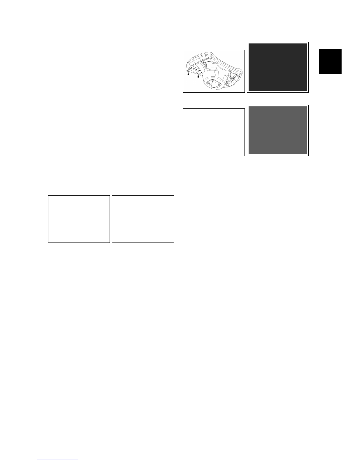
4.1.1 Key Switch
• Put the machine in safe conditions.
• Remove the screws that secure the
front carter to the steering column
(see fig. 4.1.1-1).
• Disconnect the wires connected to
the key switch.
• Unscrew the ring nut that secures
the key switch to the steering column (see fig. 4.1.1-2).
• Remove the key switch.
• Proceed at reverse to refit the part.
4.1.1-1 4.1.1-2
4.1.2 Steering Control Card
• Put the machine in safe conditions.
• Remove the screws that secure the
upper and lower part of the steering
wheel (see fig. 4.1.2-3).
• Separate the top part from the bottom part.
• Disconnect the communication cable between the Control card and the
Main card (see fig. 4.1.2-4).
• Unscrew the screws on the control
card from the top part and remove
the card (see fig. 4.1.2-4).
• Proceed at reverse to refit the part.
4.1.2-3 4.1.2-4
4.1.2-5 4.1.2-6
4.1.3 Main Card FSR B
• Put the machine in safe conditions.
• Remove the screws of the footrest
without removing it.
• Remove the screws to remove the
electrical system cover (see fig. 4.1.2-5).
• Disconnect the electrical wiring of
the Main card.
• Remove the screws that secure the
card to the support bracket and remove the card (see fig. 4.1.2-6).
• Proceed at reverse to refit the part.
4.1.4 Main Card FSR H
• Put the machine in safe conditions.
• Lift the upper body / seat.
• Loosen the screws to remove the
card protection cover (see fig. 4.1.4-7).
• Disconnect the electrical wiring of
the Main card.
• Remove the screws that secure the
card to the support plate to the
frame (see fig. 4.1.4-8).
Page 20

4-20
• Remove the card.
• Proceed at reverse to refit the part.
4.1.4-7 4.1.4-8
4.1.5 Microswitch
• Put the machine in safe conditions.
• Remove the screws that secure the
front carter to the steering column
(see fig. 4.1.5-9).
• Disconnect the wires connected to
the microswitch.
• To remove the microswitch, unscrew
the two screws and remove the device (see fig. 4.1.5-10).
• Proceed at reverse to refit the part.
4.1.5-9 4.1.5-10
4.1.6 Emergency Button FSR B
• Put the machine in safe conditions.
• Remove the screws to remove the
electrical system cover (see fig. 4.1.6-11).
• Disconnect the electrical wiring of
the emergency button (see fig. 4.1.6-12).
• Remove the screws to remove the
emergency button (see fig. 4.1.6-13).
• Proceed at reverse to refit the part.
4.1.6-11 4.1.6-12
4.1.6-13
4.1.7 Emergency Button FSR H
• Put the machine in safe conditions.
• Remove the screws that secure the
front carter to the steering column
(see fig. 4.1.7-14).
• Disconnect the electrical wiring of
the emergency button (see fig. 4.1.7-15).
• Remove the emergency button.
• Proceed at reverse to refit the part.
4.1.8 Traction Pedal
• Put the machine in safe conditions.
• Unscrew the screws that hold the
traction pedal cover and remove it (see
fig. 4.1.8-16).
Page 21

4-21
4.1.7-14 4.1.7-15
• Unscrew the screws that hold the
flap pedal cover and remove it (see fig.
4.1.8-17).
• Remove the screws to remove the
footrest (see fig. 4.1.8-18).
• Release the footswitch connector
and unscrew the two screws holding
the pre-assembly pedal (see fig. 4.1.8-19).
• Remove the pedal.
• Proceed at reverse to refit the part.
4.1.8-16 4.1.8-17
4.1.8-18 4.1.8-19
4.1.9 Dead Man Switch (Seat
microswitch)
• Put the machine in safe conditions.
• Remove the seat from the machine
(see section 4.5.8 at page 32) (see fig. 4.1.9-20).
• Remove the switch connecting joints
(see fig. 4.1.9-21).
• Remove the dead man Switch.
• Proceed at reverse to refit the part.
4.1.9-20 4.1.9-21
4.1.10 Curve Speed Reduction
Switch
• Put the machine in safe conditions.
• Unscrew the screws that hold the
traction pedal cover and remove it (see
fig. 4.1.10-22).
• Unscrew the screws that hold the
flap pedal cover and remove it (see fig.
4.1.10-23).
• Remove the screws to remove the
footrest (see fig. 4.1.10-24).
• Disconnect the wires connected to
the switch (see fig. 4.1.10-25).
• Unscrew the two screws holding the
switch to the frame and remove it together with the protective plate (see fig.
4.1.10-26).
• Proceed at reverse to refit the part.
4.1.11 Headlight
• Put the machine in safe conditions.
• Remove the screws that secure the
headlight cover to the machine body
(see fig. 4.1.11-27).
Page 22

4-22
4.1.10-22 4.1.10-23
4.1.10-24 4.1.10-25
4.1.10-26
• Disconnect the headlight cables (see
fig. 4.1.11-28).
• Remove the headlight from the headlight cover.
• Proceed at reverse to refit the part.
4.1.11-27 4.1.11-28
4.1.12 Batteries FSR H
• Put the machine in safe conditions.
• Remove the screws that secure the
left side grid to the machine (see fig.
4.1.12-29).
• Remove the screws that secure the
main card support to the machine.
• Remove the batteries.
• Proceed at reverse to refit the part.
4.1.12-29
Page 23

4-23
4.2 Main Broom System
4.2.1 Side Carter
• Put the machine in safe conditions.
• Unscrew the pin and remove the side
carter taking care not to lose the
spacer (see fig. 4.2.1-30).
• Proceed at reverse to refit the part.
4.2.1-30
4.2.2 Main Broom
• Put the machine in safe conditions.
• Open the left side Carter.
• Unscrew the fixing knob (see fig. 4.2.2-
31).
• Unscrew the fixing wing nuts and remove the lifting arm (see fig. 4.2.2-32).
• Pull the main brush lateral to the
machine (see fig. 4.2.2-33).
• Remove the pentagon from the
brush.
• Proceed at reverse to refit the part.
4.2.3 Main Broom Motor
• Put the machine in safe conditions.
• Open the right side Carter.
• Disconnect the brush motor connec-
tor (see fig. 4.2.2-34).
4.2.2-31 4.2.2-32
4.2.2-33 4.2.2-34
4.2.2-35 4.2.2-36
• Loosen the screws securing the motor to the machine (see fig. 4.2.2-35).
• Remove the motor (see fig. 4.2.2-36).
• Proceed at reverse to refit the part.
4.2.4 Main Broom Motor Bearing
• Put the machine in safe conditions.
• Disassemble the Main Broom Motor
(see section 4.2.3 at page 23).
• Loosen the screws securing the motor bearing support.
• Remove the snap ring.
• Remove the bearing from the sup-
port (see fig. 4.2.4-37).
• Proceed at reverse to refit the part.
Page 24

4-24
4.2.4-37
4.2.5 Main Broom Lifting Wire
• Put the machine in safe conditions.
• Remove the screws that secure the
front carter to the steering column
(see fig. 4.2.5-38).
• Remove the screw that secures the
wire to the internal lifting lever of the
the main broom (see fig. 4.2.5-39).
• Remove the connecting link that secures the lifting chain to the wire (see
fig. 4.2.5-40).
• Unscrew the nuts securing the
sheath to the frame and the steering
column.
• Pull the main broom lifting wire.
• Proceed at reverse to refit the part.
4.2.5-38 4.2.5-39
4.2.5-40
4.2.6 Main Broom Lifting Chain
• Put the machine in safe conditions.
• Remove the chain joints that fasten
it to the wire and to the main brush
lift lever (see fig. 4.2.5-40).
• Remove the chain.
• Proceed at reverse to refit the part.
4.2.7 Main Broom Gas Spring
• Put the machine in safe conditions.
• Open the right side carter.
• Loosen the fixing pins of the gas
spring to the supports on the machine.
• Remove the Gas Spring (see fig. 4.2.7-41).
• Proceed at reverse to refit the part.
4.2.7-41
4.2.8 Side Flap
• Put the machine in safe conditions.
• Open the right side carter.
• Loosen the screws securing the flap
to the support (see fig. 4.2.8-42).
• Remove the right side Flap being
careful not to damage or lose the
rubber blade.
• Do the same with the left side flap.
• Proceed at reverse to refit the part.
Page 25

4-25
4.2.8-42 4.2.8-43
4.2.8-44
4.2.9 Rear Flap
• Put the machine in safe conditions.
• Loosen the fixing screws of the rear
flap (see fig. 4.2.8-43).
• Remove the rear Flap.
• Proceed at reverse to refit the part.
4.2.10 Front Flap
• Put the machine in safe conditions.
• Loosen the fixing screws of the front
flap to the support (see fig. 4.2.8-44).
• Remove the front Flap.
• Proceed at reverse to refit the part.
4.2.11 Front Flap Pedal
• Put the machine in safe conditions.
• Unscrew the screws that hold the
traction pedal cover and remove it (see
fig. 4.2.11-45).
• Unscrew the screws that hold the
flap pedal cover and remove it (see fig.
4.2.11-46).
• Remove the screws to remove the
footrest (see fig. 4.2.11-47).
• Unhook the flap control rod (see fig.
4.2.11-48).
• Unhook the return spring from the
pedal.
• Unscrew the nut that hold the pedal
to the frame (see fig. 4.2.11-49).
• Remove the pedal.
• Proceed at reverse to refit the part.
4.2.11-45 4.2.11-46
4.2.11-47 4.2.11-48
4.2.11-49
4.2.12 Front flap support
• Put the machine in safe conditions.
• Disconnect the front flap support re-
lease spring (see fig. 4.2.12-50).
• Remove the front flap pedal (see section
4.2.11 at page 25).
Page 26

4-26
• Remove the screws that secure the
front flap support to the machine
frame (see fig. 4.2.12-51).
• Remove the front flap support (see fig.
4.2.12-52).
• Proceed at reverse to refit the part.
4.2.12-50 4.2.12-51
4.2.12-52
4.3 Side Broom System
4.3.1 Side Broom
• Put the machine in safe conditions.
• Make sure that the side broom is
lifted.
• Unscrew the wing nut securing the
brush to the support (see fig. 4.3.1-53).
• Remove the brush, paying attention
to the fixing bushing.
• Proceed at reverse to refit the part.
4.3.1-53
4.3.2 Side Broom Flange
• Put the machine in safe conditions.
• Remove the side broom (see section 4.3.1
at page 26).
• Unscrew the fixing dowel of the motor shaft (see fig. 4.3.2-54).
• Remove the flange (see fig. 4.3.2-55).
• Proceed at reverse to refit the part.
4.3.3 Side Broom Motor
• Put the machine in safe conditions.
• Remove the side broom (see section 4.3.1
at page 26).
• Remove the side broom flange (see sec-
tion 4.3.2 at page 26).
Page 27

4-27
4.3.2-54 4.3.2-55
• Unplug the motor connector.
• Unscrew the screws fixing the motor
to the mobile support (see fig. 4.3.3-56).
• Pull the motor to remove it.
• Remove the shaft and the key (see fig.
4.3.3-57).
• Proceed at reverse to refit the part.
4.3.4 Side Broom Lifting Wire
• Put the machine in safe conditions.
• Remove the screws that secure the
front carter to the steering column
(see fig. 4.3.3-58).
• Remove the screw that secures the
wire to the internal lifting lever of the
the side broom (see fig. 4.3.3-59).
• Loosen the screw that secures the
wire to the support of the side brush
motor (see fig. 4.3.3-60).
• Unscrew the nuts securing the
sheath to the frame and the steering
column.
• Pull the side broom lifting wire.
• Proceed at reverse to refit the part.
4.3.3-56 4.3.3-57
4.3.3-58 4.3.3-59
4.3.3-60
Page 28

4-28
4.4 Vacuum System
4.4.1 Vacuum Motor
• Put the machine in safe conditions.
• Lift the upper body / seat.
• Remove the vacuum fan (see section 4.4.2
at page 28).
• Remove the vacuum motor support,
by unscrewing the wing nuts (see fig.
4.4.1-61) (see fig. 4.4.1-62).
• Disconnect the motor connector.
• Unscrew the screws fixing the motor
support plate to the vacuum group
support plate (see fig. 4.4.1-63).
• Remove the fan hub and its key (see
fig. 4.4.1-64).
• Unscrew the screws fixing the motor
to the support plate (see fig. 4.4.1-65).
• Remove the motor.
• Proceed at reverse to refit the part.
4.4.2 Vacuum Fan
• Put the machine in safe conditions.
• Remove the Vacuum motor (see section
4.4.1 at page 28).
• Uncsrew the screw securing the Fan
to the fan Hub (see fig. 4.4.2-66).
• Remove the Vacuum Fan (see fig. 4.4.2-
67).
• Proceed at reverse to refit the part.
4.4.1-61 4.4.1-62
4.4.1-63 4.4.1-64
4.4.1-65
4.4.2-66 4.4.2-67
4.4.3 Air Filter
• Put the machine in safe conditions.
• Unscrew the wing nuts that secure
the vacuum group support plate to
the machine frame (see fig. 4.4.3-68) (see fig.
4.4.3-69).
• Unscrew the wing nuts of the filter
locking bracket (see fig. 4.4.3-70).
• Remove the filter press bracket and
then the filter (see fig. 4.4.3-71).
• Proceed at reverse to refit the part.
Page 29

4-29
4.4.3-68 4.4.3-69
4.4.3-70 4.4.3-71
4.4.4 Filter shaker
• Put the machine in safe conditions.
• Remove the air filter (see section 4.4.3 at
page 28).
• Remove the filter shaker support (see
fig. 4.4.4-72).
• Disconnect the filter shaker connector.
• Unscrew the screws securing the filter shaker to its support (see fig. 4.4.4-73).
• Remove the filter shaker (see fig. 4.4.4-
74).
• Proceed at reverse to refit the part.
4.4.5 Wheels of the Debris Hopper
• Put the machine in safe conditions.
• Remove the debris hopper from the
machine.
• Remove the screw securing the
wheel to the debris hopper (see fig. 4.4.5-
75) (see fig. 4.4.5-76).
4.4.4-72 4.4.4-73
4.4.4-74
• Remove then wheel.
• Do the same for the other wheels of
the hopper.
• Proceed at reverse to refit the part.
4.4.5-75 4.4.5-76
Page 30

4-30
4.5 Frame and Traction
System
4.5.1 Front Wheel
• Put the machine in safe conditions.
• Lift up the front wheel from the
ground.
• Unscrew one of the fixing screws of
the wheel shaft to the support (see fig.
4.5.1-77).
• Remove the wheel securing shaft to
the support taking care not to lose
the spacer.
• Proceed at reverse to refit the part.
4.5.1-77
4.5.2 Rear Wheel
• Put the machine in safe conditions.
• Lift up the related rear wheel from
the ground.
• (Only FSR B) Remove the hub cap by
levering with a small flat screwdriver
(see fig. 4.5.2-78).
• Loosen the fixing bolt of the wheel to
the axle shaft (see fig. 4.5.2-79).
• Proceed at reverse to refit the wheel
(Use the thread lock liquid on the
screw during the assembling).
4.5.2-78 4.5.2-79
4.5.3 Drive shaft
• Put the machine in safe conditions.
• Remove the wheel connected to the
concerned axle (see section 4.5.2 at page 30).
• Remove the flange and the bearing
(see fig. 4.5.3-80).
• Remove the drive shaft from the
traction motor using, if necessary,
an extractor (see fig. 4.5.3-81).
• Proceed at reverse to refit the part.
4.5.3-80 4.5.3-81
4.5.4 Traction Gearmotor
• Put the machine in safe conditions.
• Remove the rear wheels (see section 4.5.2
at page 30).
• Remove the drive shafts from the
machine.
• Disconnect the electrical connector
of the Traction Gearmotor.
Page 31

4-31
• Remove the screws securing the
Traction Gearmotor to the machine
frame (see fig. 4.5.4-82).
• Remove the traction gearmotor.
• Remove the brackets and bearing by
unscrewing the fixing screws.
• Proceed at reverse to refit the part.
4.5.4-82
4.5.5 Steering Chain
• Put the machine in safe conditions.
• Remove the front carter from the
steering column by loosening the
screws (see fig. 4.5.5-83).
• Loosen the screws that secure the
lower support of the steering shaft
(see fig. 4.5.6-87).
• Loosen the chain draw dowels and
the locknuts (see fig. 4.5.5-85).
• Remove the chain joint (see fig. 4.5.5-86).
• Remove the chain from the steering
column.
• Proceed at reverse to refit the part.
4.5.6 Steering shaft
• Put the machine in safe conditions.
• Remove the front carter from the
steering column by loosening the
screws.
4.5.5-83 4.5.5-84
4.5.5-85 4.5.5-86
• Remove the Steering Chain (see section
4.5.5 at page 31).
• Loosen the upper dowels from the
universal joint (see fig. 4.5.6-87).
• Remove the steering wheel from the
machine.
• Remove the column support and the
chain tensioner bracket by loosening
the screws (see fig. 4.5.6-88).
• Loosen the dowels of the bearing.
• Pull out the steering column from
the lower support.
• Proceed at reverse to refit the part.
4.5.6-87 4.5.6-88
Page 32

4-32
4.5.7 Sprocket, Support and
Bearings Front Wheel
• Put the machine in safe conditions.
• Remove the footrest.
• Remove the steering chain (see section
4.5.5 at page 31).
• Lift the front wheel off the ground.
• Remove the screws securing the
front wheel to the frame and remove
the wheel (see fig. 4.5.7-89).
• Remove the sprocket fixing screws
(see fig. 4.5.7-90).
• Remove bearing and the lever and
disassemble the sprocket.
• Remove the Front Wheel (see fig. 4.5.7-
91).
• Remove the bearings pin.
• Remove the bearings (see fig. 4.5.7-92) (see
fig. 4.5.7-93).
• Proceed at reverse to refit the part.
ATTE NTIO N: WH EN ASS EMBL ING, PAY
EX TREM E ATTE NTION AT THE CORRECT
PO SITI ONING OF THE S PACE R 436224,
BE CAUS E I T IS FUND AMENTAL F OR THE
PR OPER FUNCTION ING OF THE PAR T.
4.5.8 Seat
• Put the machine in safe conditions.
• Loosen the screws securing the seat
to the machine body (see fig. 4.5.8-94) (see
fig. 4.5.8-95).
• Remove the seat (see fig. 4.5.8-96).
• Proceed at reverse to refit the part.
4.5.7-89 4.5.7-90
4.5.7-91 4.5.7-92
4.5.7-93
4.5.8-94 4.5.8-95
4.5.8-96
Page 33

4-33
4.6 Endothermic Engine
System
4.6.1 Motore Endotermico
• Put the machine in safe conditions.
• Lift the upper body / seat.
• Disconnect the machine connector
(see fig. 4.6.1-97).
• Remove the right and left side grill
(see fig. 4.6.1-98) (see fig. 4.6.1-99).
• Disconnect the battery loop wire (cable with 80 Amp. fuse) (see fig. 4.6.1-100).
• Remove the upper protection of the
motor (see fig. 4.6.1-101).
• Remove the debris Hopper.
• Remove the cover alternator cover,
unscrewing the screws (see fig. 4.6.1-102).
• Disconnect the alternator cable.
• Disconnect the ground wire from the
motor.
• Disconnect the connection cables of
the motor.
• Remove the air conveyor of the motor
by unscrewing the screws.
• Remove the exhaust pipe of the engine by unscrewing the fixing screws
(see fig. 4.6.1-103).
• ATTENTION. Once you remove the
exhaust pipe, be sure to plug the
hole on the motor to prevent impurities from entering the motor itself,
risking to damage it.
• Remove the screws securing the motor to the machine frame (see fig. 4.6.1-
104).
• Lift the motor, tilting toward the rear
of the machine.
• Proceed at reverse to refit the part.
4.6.1-97 4.6.1-98
4.6.1-99 4.6.1-100
4.6.1-101 4.6.1-102
4.6.1-103 4.6.1-104
4.6.2 Alternator
• Put the machine in safe conditions.
• Remove the alternator cover, un-
screwing the screws (see fig. 4.6.2-105).
• Disconnect the alternator cables (see
fig. 4.6.2-106).
• Remove the screws securing the alternator to the motor (see fig. 4.6.2-107).
Page 34

4-34
• Remove the screw securing the belt
tensioner to the alternator (see fig. 4.6.2-
108).
• Remove the belt of the alternator.
• Proceed at reverse to refit the part.
4.6.2-105 4.6.2-106
4.6.2-107 4.6.2-108
4.6.3 Silent Block
• Put the machine in safe conditions.
• Remove the motor (see section 4.6.1 at page
33).
• Remove the screws securing the
silent block to the motor support.
• Proceed at reverse to refit the part.
4.6.4 Air Filter
• Put the machine in safe conditions.
• Remove the filter protective cover (see
fig. 4.6.4-109).
• Remove the air filter (see fig. 4.6.4-110).
• Proceed at reverse to refit the part.
4.6.4-109 4.6.4-110
Page 35

4-35
Part III
Machine Description
35
Page 36

5-36
Chapter 5
Electrical System
The FSR sweeper is available in two versions, FSR B and FSR Hybrid. Both versions are equipped with a main card that
controls all functions and the power output. FSR B model is battery powered
while the Hybrid version offers a combined gasoline motor and battery power
supply.
Figure 5.1: Electrical System FSR B
Figure 5.2: Electrical System FSR Hybrid
5.1 Structure
1. Main Card
2. Control Card
3. Microswitches: main broom motor,
side broom motor, vacuum motor,
curve speed reduction and deadman
seat
4. Electrobrake
5. Emergency button
6. attery charger (FSR B only)
7. Traction Pedal
8. Batteries
36
Page 37

5-37
5.2 Description
A main card runs all the functions of the
machine, sweep, vacuum, traction and
filtershake.
The main card receive as input, all the
information from the control card, the
deadman microswitch, the curve speed
reduction microswitch, the brooms control microswitch, and all the electronic
devices of the machine.
These signals are translated from the
main card to run correctly the scrubber
dryer and to prevent any safety problem
to the operator.
The dash board can be used also as a
programmer console to modify the parameter of all the machine’s functions
(traction, sweeping and vacuum) and,
also, to check the consumption of all the
motors and batteries.
Page 38

5-38
5.2.1 Location of Electrical components FSR B
Page 39

5-39
List of Components
CBR Battery charger
1
J3 Control Card
J Main Card
FE Emergency button
LAMP Safety blinking light
M1 Traction Motor
M1E Traction Motor electrobrake
M2 Main Broom Motor
M3 Vacuum Motor
ML Control microswitches
MS Seat microswitch
MULTIM Curve sensor microswitch
PM Potentiometer and pedal microswitch
M5 Filter Shaker Motor
FA Headlights
J8 Right/Left Side Broom Motor
1
Optional
Page 40

5-40
5.2.2 Location of Electrical components FSR Hybrid
Page 41

5-41
List of Components
J3 Control Card
J Main Card
FE Emergency button
LAMP Safety blinking light
M1 Traction Motor
M1E Traction Motor electrobrake
M2 Main Broom Motor
M3 Vacuum Motor
ML Control microswitches
MS Seat microswitch
MULTIM Curve sensor microswitch
PM Potentiometer and pedal microswitch
M5 Filter Shaker Motor
FA Headlights
J8 Right/Left Side Broom Motor
CH General Key Switch
MENA Endothermic Motor and Alternator
BATT Rechargeable Batteries
Page 42

5-42
5.2.3 Main Card
The Main Card is the heart of the machine and, depending of the input information, decides how to use the devices
of the machine during normal work. On
the table here below, is possible to identify the input/output signals of the card.
5.2.3-1 5.2.3-2
Input & Output Signals
F1 Key general fuse (3A).
J1 Vacuum motor and Main Broom mo-
tor.
J2 Traction motor.
J3 Electrobrake, blinking light, Head-
lights, filter shaker.
J6
Dashboard control buttons.
J7 Limit switch: Broom motor, vacuum
motor, curve speed reduction, dead-
man switch, traction control, battery
charger (FSR B), alternator (FSR Hy-
brid), potentiometer.
J8 Right side broom Motor.
J9 Optional left side broom Motor.
5.2.4 Dashboard and Control
card
Functions of Dashboard:
• Manage and set up the main functions and command of the machine
during the normal work.
• Check the alarm code in order to detect a possible malfunction.
• Enter in three different menu:
– The “user menu” to check the
status of the batteries and the
hourmeter of the machine (depending of the set up into “user
menu”). If a defect is detected
on the machine, this menu
show a short message concerning the alarm.
– The “operator menu” contain-
ing the basic adjustment, accessible by the user of the machine.
– The “advanced menu” where is
possible to modify the set up of
the machine by expert technicians.
ATTE NTIO N: TH E “OPE RATOR M ENU”
IS AC CESS IBLE WIT HOUT ANY RE STRI C-
TI ON, WHE REAS TO ENTE R I NTO THE “AD-
VANCED MENU ” A P ASSWORD IS NEE DED.
Page 43

5-43
Functions and Commands
During the normal working, the display
shows the hourmeter and the battery
control card (in percentage). When the
charge of the batteries goes down to a
fixed value, the battery control card disable the brush motor and, after that, the
vacuum motor; in particular, the battery
control card disable the brush motor
(vacuum motor and traction motor still
work) when the remaining charge of the
batteries are 20% and disable also the
vacuum motor when the remains charge
of the batteries are 10%.
5.2.4-3 5.2.4-4
Entry into “Operator Menu” and “Advanced Menu”
The dashboard could be used like a programming console. If you press a determinate combination of buttons you can
enter into two menu:
• “Operator Menu”.
• “Advanced Menu”.
The structure of the menu can be shown
in the section (see section 5.6.1 at page 53):
Function of the buttons
1 Not Used
2 ENTER (Confirm)
3 SCROLL UP/PLUS (Scroll up and In-
crease)
4 SCROLL DOWN/MINUS (Scroll down
and Decrease)
Page 44

5-44
Operator Menu
To enter to the Operator menu go ahead
as follow:
• With the machine off, press in the
same time button “2”, “3” and “4”.
• Turn on the key, with the three buttons pressed.
• Waiting the upload of the “working
menu”.
• Release the buttons.
To move inside of the menu, press the
button “3” and the button “4”.
To modify a parameter or confirm a
changed value, press the button “2”.
Change a Parameter (in the Operator
Menu)
To change a parameter proceed as follows:
• Run the menu with the button “3”
or “4” and select the parameter to
change.
• Select the submenu to be changed
pressing the button “2”.
• Utilize the button “3” and “4”, to shift
all the available values for the parameter necessary to modify.
• To confirm the new value press the
button “2”.
• To save the change is necessary to
return to the user menu; to exit from
“working menu” select the menu
“exit”.
For example, to modify the language
from EN to IT
• Turn OFF the machine.
• Press in the same time, the buttons
“2”, “3” and “4”.
• Until the buttons are pressed, turn
ON the key and wait the upload of
the “working menu”.
• Use the buttons “3” or “4” to select
the submenu “language”.
• To modify the parameters of this
menu, press the button “2”. To confirm the possibility to change parameters, the first line on the display will
blink.
• Utilize buttons “3” or “4” to shift all
the values on this menu and select
the value “IT”.
• Confirm the new value by pressing
the button “2”.
• To save this modification, select
the submenu “exit” and confirm by
pressing button “2”.
Page 45

5-45
Advanced Menu
The Advanced Menu can be reached
from the “operator menu” by accessing
the “password” parameter and setting
the value 60.
Change a Parameter (in the Advanced
Menu)
To change the value of a parameter, proceed as follows:
• Scroll through the submenus with
the buttons “3” and “4”.
• Select the submenu that contains
the parameters to be changed using
the button “2”.
• Scroll through the parameters with
the buttons “3” and “4” to find the
parameter to be edited.
• Select the parameter with the button
“2”.
• Use the buttons “3” and “4” to scroll
through the list of available values of
the parameter.
• Confirm the new value of the parameter using the button “2”.
• To enable the changes, it is necessary to return to the “menu work”;
to exit the parameters and return to
the “Advanced Menu” press simultaneously the buttons “3” and “4”,
then find the sub-menu “Exit” and
confirm with button “2”.
Check/Monitor Function
It is possible to view all the values of the
Check/monitor function during the normal work of the machine. To view the
values, following the instruction:
• Turn OFF the machine.
• Press in the same time, the buttons
“2”, “3” and “4”.
• Until the buttons are pressed, turn
ON the key and wait the upload of
the “working menu”.
• Use the buttons “3” or “4” to select
the submenu “password”.
• Confirm pressing button “2”.
• Press button “3” or “4” until to select
the password “60”.
• Confirm the password by pressing
the button “2” to enter into the “advanced menu”.
• Press the button “3” or “4” to select
the menu “Check/Monitor”.
• Confirm by pressing the button “2”.
• Press the button “3” or “4” to se-
lect the parameter you want to check
during normal work.
• Press the button “2” to confirm.
• After confirmed, the display will re-
turn to normal view, but instead of
the battery control card it will be displayed the value of the selected parameter.
• By pressing the button “2” it is possible to check the parameters of the
Check/Monitor submenu.
• To exit form the “Check/Monitor”
view, turn OFF and ON the machine.
Page 46

5-46
5.2.5 Control Card
The Control Card is located inside of the
steering wheel and transfers all the information and settings to the Main Card.
The Control Card is linked to the Main
Card by a connecting cable (item J6).
5.2.6 Microswitches
The machine is provided with a series of
microswitches that send signals to the
main card. In particular:
• Main broom and vacuum motor Microswitch. With lowered main broom
lifting lever and closed micro, the
deck goes down to the floor and, the
broom motor and the vacuum motor, starts running (as long as the
traction pedal is pressed and the operator is seated). The sweeping and
vacuum function is active.
• Side broom motor Microswitch. Lowering the side broom lifting lever,
and closed micro, the broom support
goes down to the floor and the broom
motor starts running (as long as the
traction pedal is pressed, the main
broom is lowered and the operator is
seated).
Page 47

5-47
In the case of double side brush, the
process does not change.
• Curve speed reduction Microswitch.
it is positioned below the platform,
tangent to a cam. After a predetermined angle of rotation of the
steering, the microswitch opens and
the curve speed reduction function
is activated. The percentage of the
speed reduction is an adjustable parameter.
• Deadman Microswitch. The micro
switch is located below the seat.
With the operator on board, the traction and the brush deck can be activated.
5.2.7 Electrobrake
The machine is equipped with electrobrake. The electro-brake is engageable
through an appropriate control lever positioned on the electro-brake itself, close
to the traction motor. looking at a global
security condition, even if the machine is
switched off and the electrobrake is disengaged, the electrobrake blocks however, in case of exceeding a certain speed
(when pushing the machine or if the machine is on an inclined floor). If the machine is switched on, the drive is inhibited if the electrobrake is disengaged.
Page 48
5-48
5.2.8 Emergency button
The machine is equipped with an emergency button, aimed at the protection
of the operator in case of sudden critical conditions. A press of the button
switches off the power to the Main card
and the machine stops immediately.
FSR B: the button is located on the electrical system cover.
FSR Hybrid: the button is located on the
steering wheel column.
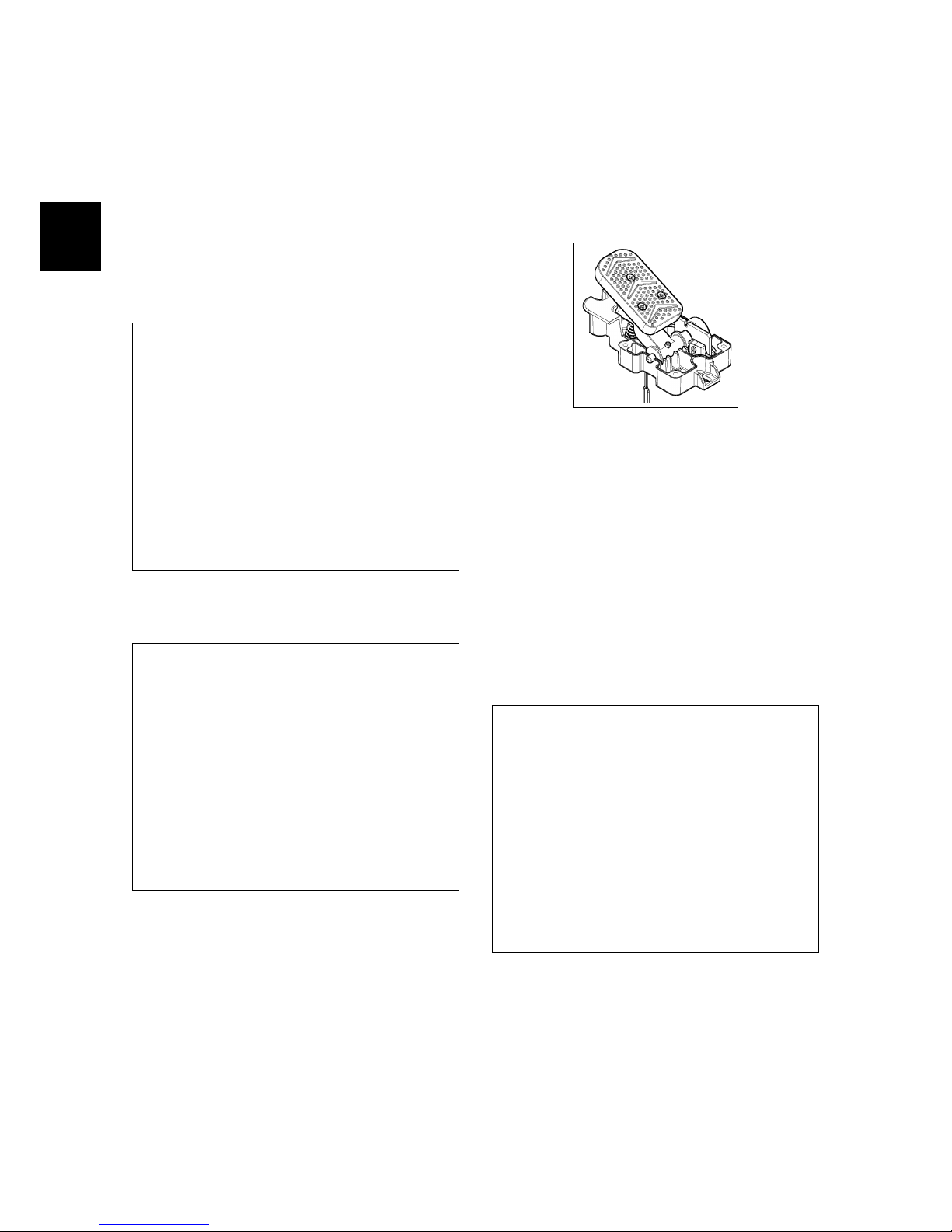
5.2.9 Traction Pedal
The traction pedal have an internal microswitch that closes when the pedal is
pressed and a potentiometer to adjust
the intensity of the traction speed.
5.2.9-5
5.2.10 Battery charger
The machine with Battery power supply is available with the optional battery
charger. To get access to the battery
charger and the battery compartment is
enough to lift the seat.On the batteries
there is a loop wire with 80 Ampere general protection fuse.
Page 49
5-49
5.3 Adjustments
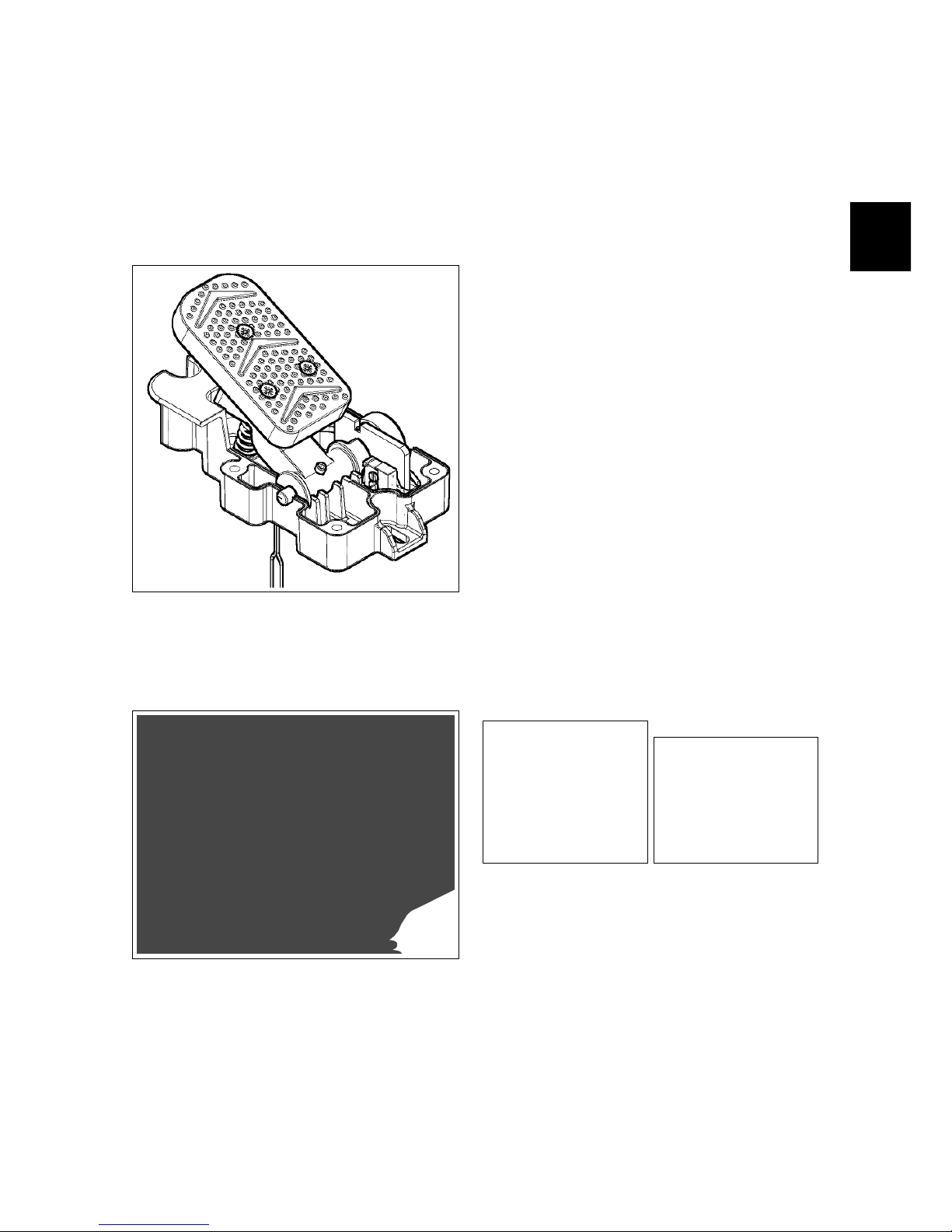
5.3.1 Traction Pedal
The microswitch and the potentiometer
inside the traction pedal are properly adjusted during assembly of the pedal.
If it is necessary to calibrate the potentiometer remove the platform, release
the control connector and pull the pedal
out by unscrewing the two screws.
Procedure:
• Remove the plastic cap and loosen
the adjustment dowel.
• Rotate the pedal lateral spindle
clockwise, until it is in the zero position.
• Using the tester to measure the re-
sistance (Ω) place the tester terminals corresponding to the green and
yellow wires and check the resistance value to be approximately zero
Ω.
• Turn the potentiometer shaft counterclockwise until the tester gives
0,5 Ω (± 0,1).
• Lock the dowel and replace the plastic cap.
• Reinstall the pedal and the footrest.
5.3.2 Microswitch
Check functionality and conditions of
the vacuum/main broom microswitch,
the side broom microswitch, and the
curve speed reduction microswitch.
Check that with microswitch pressed,
remain about 0.5 mm clearance between
the lever and the body of the device.
Make sure the lever of the micro is working properly. Otherwise, proceed as follows:
5.3.2-6 5.3.2-7
• Unscrew the fixing screws.
• Move the DIP switches using the
loop adjustment.
• Fix the screws to lock the mi-
croswitches taking care not to over
tighten in order not to ruin the devices.
Page 50

5-50
• When the setting is finished, verify
the correct functionality of the microswitches.
5.3.3 Battery Charger (FSR B)
The battery charger is positioned behind
the operator’s seat and is easily accessible by pressing the release button on the
recovery tank. When connected to the
power supply, a red led will blink once,
the yellow led blink once and the green
led blink depending of the type of battery
for which the charger is set.
A Proper Charging cycle follows the below phases order.
Phase LED Description
A Red Blinking, check of battery
status
B Red First charging phase
C Yellow Second charging phase
D Green Charged battery
Check if the charger is properly set according to the installed batteries.
Charging curve SetUp
To set up the charger, follow the instructions:
• Use a screwdriver to remove the
small black plastic cap
• Set-up the internal dipswitches according to the following table
The dipswitches are divided in two couple. The higher couple are the dipswitches 1 and 2, the couple down are
the dipswitches 3 and 4. The following table shows how to setup the dipswitches 1 and 2.
DP3: OFF (not used)
DP4: OFF (not used)
Restore the the small black plastic cap.
Set-up of Charging Curve
DP1 DP2 Set Up Flash
OFF OFF Wet cell batteries 1
ON ON Gel TROJAN 2
OFF ON Generic GEL or
AGM batteries
3
ON OFF Gel EXIDE SON-
NENSCHEIN
4
5.3.3-8 5.3.3-9
Error Codes of Charger
The charger have an alarm system. The
alarm code is shown by blinks of the yellow led.
Error code
Flash Description
1 Wrong battery, Inverted polarity,
short circuit to the exit
2 Timeout alarm, Defect of the bat-
tery
3 Defect of the Charger
4 Overtemperature alarm
Page 51

5-51
5.4 Maintenance and
Checks
5.4.1 Electrical System
Check (to perform every 150h)
Check the functions and the proper connections of the switches, microswitches,
motors, power fuses, battery loop wires
and emergency button. Check periodically, the wiring connections status. To
get access to the electrical system:
FSR B: remove the carter sited near the
emergency button. FSR Hybrid: Lift the
upper body/seat.
5.4.2 Emergency Button
Check (to perform every 150h)
Check the correct functionality of the
emergency button. Once pressed, the
machine must stop immediately.
5.4.3 Electrobrake
Check (to perform every 150h)
Check the functionality of the electrobrake.
With control lever rotated downward
(electrobrake engaged), if you try to push
the machine, it must be locked (regardless of whether the machine is powered
or not).
With control lever rotated upward (electrobrake released), the machine must be
free to move when pushed, regardless of
whether the machine is powered or not.
With the machine powered up, if you
try to work the drive must be inhibited.
The display on the steering wheel has
to show the alarm related to the electrobrake not engaged.
5.4.4 Batteries
Check (to perform every 150h)
Check the proper connection of the Loop
wire with 80 Ampere general fuse.
5.4.4-10 FSR B 5.4.4-11 FSR Hybrid
Page 52

5-52
5.5 Alarm Table
5.5.1 Alarms
Alarms of Overcurrent and Temperature
Id Alarm Meaning Solution
AL 1: Function
Brushes Ammeter
Brush Amperometric Protection Check consumption of the brush motor. Detected high current
on brush motor.
AL 2: Function
Vacuum Ammeter
Vacuum Amperometric Protection
Check consumption of the vacuum motor. Detected high cur rent on vacuum motor.
AL 3: Function
Powerstage fail
Damage of Power Damage power of brush or vacuum: replace the main card.
This alarm could be shown also during the trailing of the machine.
AL 4: Function
Overcurrent
Output overcurrent on brush or
vacuum
Detect a shortcircuit on output brush motor or vacuum motor:
Check connections and motors.
AL 5: Function
Overtemperature
Thermal protection on
brush/vacuum
Overtemperature of brush/vacuum motor: check consumption of motors.
Traction Alarms
Id Alarm Meaning Solution
AL 13: Traction
Pedal failure
Pedal anomaly Check the connections and the condition of the pedal poten-
tiometer.
AL 14: Traction
Release Pedal
Pedal pressed before starting Detected pedal microswitch pressed before starting: release
the pedal.
AL 15: Traction
Overtemperature
Thermal protection on traction Overtemperature on traction : check consumption of traction
motor
AL 16: Traction
Powerstage fail
Power of traction damage Replace the main card.
AL 17: Traction
Overcurrent
Traction Overcurrent Detected a shortcircuit on the traction motor output: Check
connections and status of the traction motor.
AL 18: Traction
Traction Ammeter
Traction Amperometric protection
Check how the traction function is used. Detected too high
working current on traction motor.
AL 19: Traction
Electrobrake
Electrobrake not inserted Check the condition of the electrobrake and its related mi-
croswitch.
General Alarms
Id Alarm Meaning Solution
AL 20: General
EEPROM FAIL
Error reading internal memory Replace the main card.
AL 21: General
KEY-OFF FAILURE
Error key sequence Error on key signal: Check the key connection. Check, also,
the batteries connections and main card
AL 22: General
Main relay fail
Damage of general relay Check the traction motor connections. If the connection are
OK, the general relay on the main card is damaged: replace
the main card.
AL 23: General
Overvoltage
Overvoltage Detected a overvoltage on the main card. Check the batteries
connections.
AL 24: Traction
Batt.connection
Battery not connected to the
main card
Check the traction motor, Detected high voltage on traction
motor.
AL 25: General
Keyboard com.
No communication between control card and main card
Check the connections between control card and main card.
Page 53
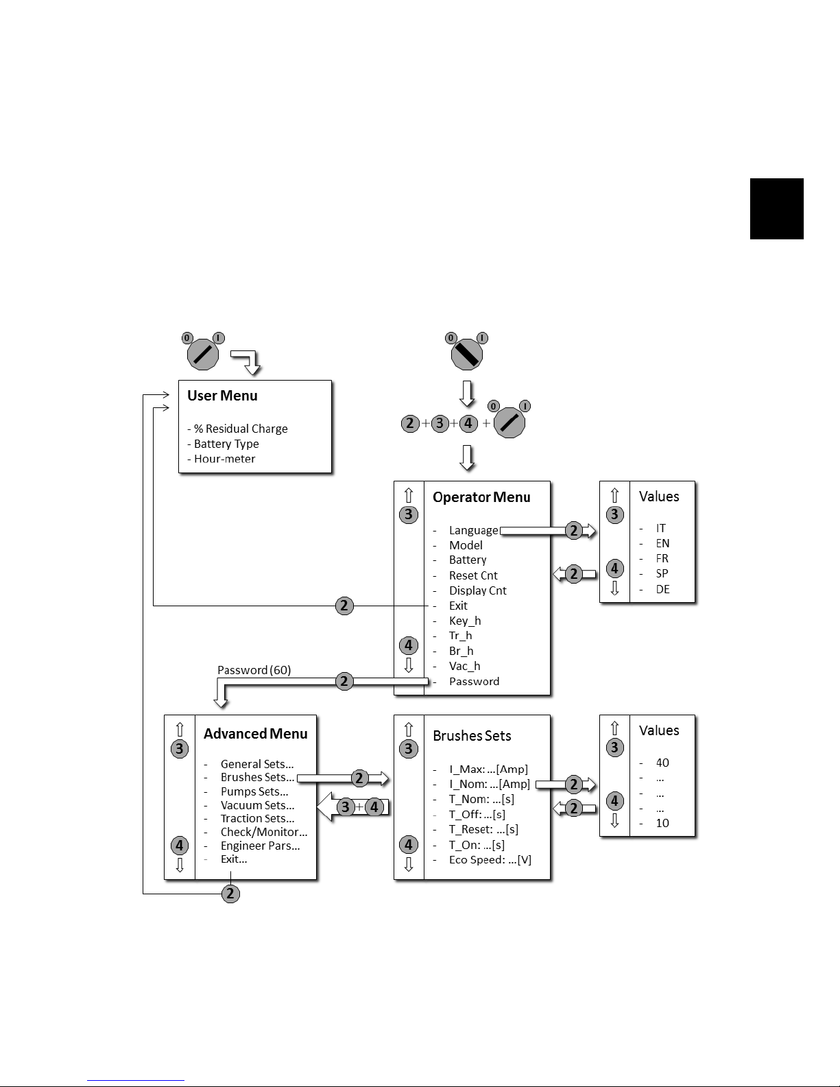
5-53
5.6 Menu tables
5.6.1 Menu scheme
• Make sure the machine is turned off.
• Press simultaneously the buttons 2,3,4.
• Turn on the machine while holding down the buttons.
• Wait the loading of the Operator Menu.
• For the submenus of the Advanced Menu, refer to the specific tables.
Page 54

5-54
5.6.2 Working Menu
MENU DEFAULT CHOICES DESCRIPTION
General Setup:
Language: ##
IT IT - EN - FR -
SP - DE
Setup language
General Setup:
Mod: #######
FSR . . . Setup type of machine
General Setup:
Battery: ###
GEL GEL - WET -
AGM - GE1 WE1
Setup kind of battery
General Setup:
Reset Cnt: #
N Reset partial hourmeter.
General Setup:
Display Cnt: ###
TR KEY - TR Select the kind of hourmeter: key connect to the key - tr.
connect to the traction motor
General Setup:
Exit. . . . . . . . . .
N Exit from the menu.
General Setup:
Key h: #### h:## m
Total hourmeter connect to the key.
General Setup:
Tr h: #### h:## m
Total hourmeter connect to the traction.
General Setup:
Br h: #### h:## m
Total hourmeter connect to the brush motor.
General Setup:
Vac h: #### h:## m
Total hourmeter connect to the vacuum motor.
General Setup:
password: ###
60 This password is necessary to enter into the “Advanced menu”,
utilized by expert technicians only.
5.6.3 Advanced Menu
MENU DESCRIPTION
Options menu:
General sets.
Enter to the general parameters (language, battery. . . ).
Options menu:
Brushes sets.
Enter to the parameters for the brush base.
Options menu:
Pumps sets.
Parameter not managed.
Options menu:
Vacuum sets.
Enter to the parameters of vacuum motor.
Options menu:
Traction sets.
Enter to the parameters of traction motors.
Options menu:
Check/Monitor.
Enter to view the list of working parameters.
Options menu:
Engineer pars.
Protected parameters (calibrations and factory settings).
Options menu:
Exit. . . ..
Exit and return to the main menu.
Page 55

5-55
General Sets
MENU DEFAULT VALUES DESCRIPTION
General Sets:
Language: ##
IT IT - EN - FR -
SP - DE
Setup the language of the display.
General Sets:
Mod: ###
FSR . . . Setup of the machine model.
General Sets:
Battery: ###
GEL GEL - WET -
AGM - GE1 WE1
Setup of the battery type.
General Sets:
Rst.Cnthr: #
N Reset partial hourmeter (like on “working menu”).
General Sets:
Rst.Main Cnthr:
N Reset total hourmeter (key, brush, vacuum, traction).
Brushes Sets
Parameter Default Min ÷ Max Description
Brushes Sets:
I Max: ## [Amp]
50 20 ÷ 80 Maximum current from the main card to the brush motor.
Brushes Sets:
I Nom: ## [Amp]
22 10 ÷ 40 Rated current; with T Nom manages the amperometric protection
(alarm + stop brush motor).
Brushes Sets:
T Nom: ## [s]
30 1 ÷ 60 Rated timer; with I Nom manages the amperometric protection
(alarm + stop brush motor).
Brushes Sets:
T Off: ### [s]
0,2 0.0 ÷ 10.0 Delay of switching off of the brush motor when the safety lever is
released.
Brushes Sets:
T Reset: ## [s]
10 0 ÷ 100 T iming of reset amperometric protection (overcurrent).
Brushes Sets:
T On: ### [s]
0,5 0.0 ÷ 5.0 Delay to switching on of the brush motor when the safety lever is
pressed.
Brushes Sets:
Eco speed: ## [V]
17 15 ÷ 20 Parameter not managed.
Pumps Sets
Parameter not managed
Page 56

5-56
Vacuum Sets
Parameter Default Min ÷ Max Description
Vacuum Sets:
I Max: ## [Amp]
40 10 ÷ 50 Maximum current from the main card to the vacuum motor.
Vacuum Sets:
I Nom: ## [Amp]
18 5 ÷ 20 Rated current; with T Nom manages the amperometric protection
(alarm + stop vacuum motor).
Vacuum Sets:
T Nom: ## [s]
30 1 ÷ 100 Rated timer; with I Nom manage the amperometric protection (alarm
+ stop vacuum motor).
Vacuum Sets:
T Off: ### [s]
0 0 ÷ 30 Delay of switching OFF of the vacuum motor when the pedal is re-
leased.
Vacuum Sets:
T reset: ## [s]
60 0 ÷ 100 T iming of reset amperometric protection (overcurrent).
Vacuum Sets:
Eco Speed: ## [V]
17 15 ÷ 20 Parameter not managed.
Page 57

5-57
Traction Sets
Parameter Default Min ÷ Max Description
Traction Sets:
Acc Ramp: ### [s]
3.0 0.5 ÷ 5.0 Acceleration ramp. The time necessary to arrive at the maximum
speed.
Traction Sets:
Dec Ramp: ### [s]
0.7 0.5 ÷ 5.0 Deceleration ramp. The time necessary to stop the machine when the
safety lever is released.
Traction Sets:
Rev Ramp: ### [s]
0.7 0.5 ÷ 5.0 The time necessary to invert the way.
Traction Sets:
FW Speed: ### [%]
100 20 ÷ 100 Maximum speed in forward way (expressed in %).
Traction Sets:
BW Speed: ### [%]
60 20 ÷ 100 Maximum speed in reverse way (expressed in % respect the maximum
speed in forward way).
Traction Sets:
Min Speed: ### [%]
0 0 ÷ 20 Minimum speed when the safety lever is pressed.
Traction Sets:
Ref 0: ## [V]
0.7 0.0 ÷ 15.0 Minimum voltage of the potentiometer when released.
Traction Sets:
Ref FW: ## [V]
0.9 0.5 ÷ 15.0 Maximum voltage of the potentiometer in forward speed when safety
lever is pressed.
Traction Sets:
Ref BW: ## [V]
0.9 0.5 ÷ 15.0 Maximum voltage of the potentiometer in backward speed when safety
lever is pressed.
Traction Sets:
Ref DB: ##### [V]
0.200 0 ÷ 0.500 Potentiometer dead band.
Traction Sets:
Brake Del: ### [S]
1.5 0.0 ÷ 10 Engaging time of electronic brake when the machine is stopped.
Traction Sets:
Mode1 V: ## [%]
50 10 ÷ 100 Voltage setting for the curve speed reduction microswitch.
Traction Sets:
Mode1 I: ## [A]
25 0 ÷ 90 Current intensity setting for the curve speed reduction microswitch.
Traction Sets:
Runaway: ### [Volt]
12 0 ÷ 20 Parameter not managed.
Traction Sets:
optional3: ##
0 0 Parameter not managed.
Traction Sets:
optional2: ##
0 0 Parameter not managed.
Traction Sets:
optional1: ##
0 0 Parameter not managed.
Traction Sets:
I Max: ## [Amp]
70 10 ÷ 90 Maximum output from the main card to the traction motor.
Traction Sets:
I Nom: ## [Amp]
20 5 ÷ 30 Rated Current; with T Nom detect the amperometric protection
threshold. (Alarm + stop traction motor).
Traction Sets:
T Nom: ## [s]
10 1 ÷ 30 Rated Timer; with I Nom detect the amperometric protection thresh-
old. (Alarm + stop traction motor).
Page 58

5-58
Check / Monitor
Check / Monitor:
I Tr: ### [Amp]
Show current of traction motor.
Check / Monitor:
I Br: ## [Amp]
Show current of central broom motor.
Check / Monitor:
I Vac: ## [Amp]
Show current of vacuum motor.
Check / Monitor:
V Tr: #### [V]
Show voltage of traction motor.
Check / Monitor:
V Batt: #### [V]
Show battery voltage.
Check / Monitor:
Vref: ### [V]
Show the voltage reference of the traction pedal.
Check / Monitor:
Wtr Pump: ### [%]
Parameter not managed.
Check / Monitor:
Det Pump: ### [%]
Parameter not managed.
Check / Monitor:
BR Temp: ## [C]
Show temperature inside of main card, related to brush/vacuum.
Check / Monitor:
TR Temp: ## [C]
Show temperature inside of main card, related to traction.
Check / Monitor:
TR Ovrld: ### [%]
Show the percentage value of the amperometric protection of traction motor (when 100%
the amperometric protection cuts the current).
Page 59

5-59
5.7 Technical Features
TECHNICAL DESCRIPTION U/M FSR B FSR Hybrid
Dimension of Battery compartment (l x L x h) mm (2x) 340x175x280 (1x) 270x360x250
Batteries Rated Voltage
V
Ah
2x(12/105) 2x(12/55)
Maximum batteries weight kg 2x36,5 2x20
5.8 Recommended Spare Parts
FSR
PN Description B Hybrid
438767 MAIN CARD
√ √
436267 CONTROL CARD
√ √
222367 TRACTION PEDAL ASSEMBLY
√ √
409261 COMPLETE KEY SWITCH
√
438121 COMPLETE KEY SWITCH
√
409499 MICROSWITCH 3X22 L.C.FLAT
√ √
409503 SEAT MICROSWITCH
√ √
216691 COMPLETE SEALED MICROSWITCH
√ √
436144 EMERGENCY BUTTON ED80
√
435489 EMERGENCY BUTTON
√
223390 BATTERY CHARGER KIT
√
Page 60

6-60
Chapter 6
Main Sweeping System
6.1 Structure
1. Command lever
2. Lifting wire
3. Wire guide
4. Broom support arm
5. Broom release knob
6. Broom left support
7. Broom left coupling
8. Broom
9. Broom right coupling
10. Main broom gearmotor
11. Gas spring
6.2 Description
The sweeping function of the machine
is assigned to the central brush. This
brush actively collects debris of medium
and large dimensions and helps the vacuum system to collect dust. The brush
has cusped bristles to prevent dirt from
accumulating on the sides of the machine, not being collected.
The support of the central brush is
moved by means of a steel cable directly
connected to the control lever on the
steering column. The steel cable and
connected by a chain, to the lifting arm
of the main brush.
The rotation of the brush is assigned to
a motor with integrated gear housed in
the core of the brush itself.
There are different types of central
brush, generally when the dirt is heavy
and of big size, it is recommended a hard
bristle and vice versa.
Similarly, is recommended a mixed
metal bristle (copper brass or similar) in
the case the machine work on plastic
material floors or carpet, so as to prevent the accumulation of electrostatic
charges.
60
Page 61

6-61
6.3 Adjustments
6.3.1 Lifting wire
The broom have move freely in his compartment. It has to touch the floor when
it is placed in the working position (regardless of the level of wear) and must be
able to be lifted without interfering with
the machine frame.
Requirements: (New) Mounted brush,
switched off machine.
Procedure:
• Lift the main brush by acting on the
lever.
• Verify that the distance between the
brush and the floor is between 15
and 20 mm.
• In case the distance is less act on the
sheath nuts of the lifting wire to adjust the height.
• Once Adjusted verify the correctness
and proceed to check tightness of all
nuts and bolts.
6.3.1-12 Brush lifting wire
6.4 Maintenance and
checks
6.4.1 Motor
Check (to perform every 150h)
The motor should rotate evenly and
smoothly. It’s important that the reduction case is not noisy and that the motor
current consumption is not higher than
the declared on the plate, regardless of
the load which it is subjected. It is necessary that the motor carbon brushes
are always in good condition and show
no signs of abnormal wear.
Maintenance (to perform every 600h)
Motor carbon brushes replacement: Procedure:
• Put the machine in safe conditions.
• Remove the motor from the machine
(see section 4.2.3 at page 23).
• Remove the plastic covers by leveraging with a small screwdriver.
6.4.1-13 Hood opening
• Replace the carbon brushes being
careful not to ruin them during assembly.
• Proceed to the reverse operations to
reassemble it all.
Page 62

6-62
6.4.2 Bearings
Check (to perform every 150h)
The bearings allow a fluid and little
tiring rotational movement of the main
broom. To prevent the main broom is
locked in a position without the possibility of movement, is important that the
bearings are in good condition and that
the rotational movement is fluid. In case
of excessive noise or difficulty in rotate,
it is necessary to replace them.
6.4.2-14 Motor bearings
6.4.3 Lifting mechanism
Check (to perform every 150h)
The lifting mechanism should be clean
and lubricated. The lubrication of the
cables must be done with silicone spray,
it should not be used any grease or
oil to prevent that the dirt paste itself
to the classics lubricants, and lock the
mechanism. The lubrication of the chain
and of the lifting mechanism must be
done with lubricant grease.
Page 63

6-63
6.5 Technical Features
TECHNICAL DESCRIPTION U/M FSR B FSR Hybrid
Width main broom mm 580 580
Diameter main broom φ mm 260 260
Main broom turns rpm 550 550
Main broom motor voltage V 24 24
Main broom motor power W 380 380
6.6 Consumable Spare Parts
PN Description Width/φ (mm) φ Bristle (mm) Bristle type
437902 MAIN BROOM 580 / 260 0.7/1.1 PPL/Bronze
438621 MAIN BROOM 580 / 260 0.7/1.1 Natural fibre
Carbon Brushes
422462 BR.MOT.CARBON BR. - - -
6.7 Recommended Spare Parts
FSR
PN Description B Hybrid
437901 GEAR MOTOR 24V 380W 600RPM
√ √
438131 GAS SPRING
√ √
437879 MAIN BROOM LIFTING WIRE
√ √
415476 MAIN BROOM LEFT COUPLING
√ √
437896 MAIN BROOM RIGHT COUPLING
√ √
Page 64

7-64
Chapter 7
Side Brush System
7.1 Structure
1. Lifting wire
2. Wire guide
3. Brush gearmotor support
4. Brush coupling flange
5. Brush
6. Side Brush gearmotor
7.2 Description
FSR is equipped with a side brush on
its right side (on the left side, can also
be mounted a second side brush upon
request).
This brush is dedicated to move dirt
close to the edges, due to the pedestrian
areas or walls, towards the center of the
machine where can be collected then by
the main brush.
For this reason the side brush is not
used in standard working conditions but
only when it is necessary to clean a particular area.
64
Page 65

7-65
7.3 Adjustment
7.3.1 Side brush support
The side brush support have to be
adjusted with a new brush properly
mounted. The adjustment of the support
is twofold:
• Lifted position Adjustment. For a
proper adjustment of the side brush
in lifted position, it is necessary to
act on the lifting wire.
7.3.1-15 Brush lifting wire
• Lowered position Adjustment. For a
proper adjustment of the side brush
in lowered position, it is necessary to
act on the adjusting screw.
7.3.1-16 Adjusting screw
Procedure
• Put the machine in safe conditions.
• Install a new side brush on the ma-
chine.
• Pull the brush in the lifted position
through the control lever.
• Verify that in this position the side
brush gearmotor rests on the machine body.
• In case it is necessary to adjust the
position act on the nuts of the lifting
cable sheath.
• Verify the functionality of the obtained setting.
• Lower the side brush to the floor.
• Make sure that the brush touches
the ground only for 2/3 of its circumference.
• If necessary act on the end stroke
screw to adjust the movement of the
brush holder.
Page 66

7-66
7.4 Maintenance and
checks
7.4.1 Side brush support
Check (to perform every 150h)
In order to operate properly, the side
brush support must be free to move
properly. The brush must in fact be able
to follow the floor and to operate freely
to the ground.
7.4.2 Side brush motor
Check (to perform every 150h)
The motor should rotate evenly and
smoothly. It’s important that the reduction case is not noisy and that the motor
current consumption is not higher than
the declared on the plate, regardless of
the load which it is subjected. It is necessary that the motor carbon brushes
are always in good condition and show
no signs of abnormal wear.
Maintenance (to perform every 600h)
Motor carbon brushes replacement: Procedure:
• Put the machine in safe conditions.
• Remove the side brush motor from
the machine (see section 4.3.3 at page 26).
• Unscrew the screws that secure the
rear hood to the motor.
• Replace the carbon brushes being
careful not to ruin them during assembly.
• Proceed to the reverse operations to
reassemble it all.
7.4.3 Lifting mechanism
Check (to perform every 150h)
The lifting mechanism should be clean
and lubricated. The lubrication of the
cables must be done with silicone spray,
it should not be used any grease or oil
to prevent that the dirt paste itself to
the classics lubricants, and lock the
mechanism.
Page 67

7-67
7.5 Technical Features
TECHNICAL DESCRIPTION U/M FSR B FSR Hybrid
Diameter side brush φ mm 400 400
Side brush turns rpm 65 65
Side brush motor voltage V 24 24
Side brush motor power W 90 90
7.6 Consumable Spare Parts
PN Description φ (mm) φ Bristle (mm) Bristle type
437874 SIDE BRUSH 400 1.0 PPL
Carbon Brushes
415981 BR.MOT.CARBON BR. - - -
7.7 Recommended Spare Parts
FSR
PN Description B Hybrid
437876 BRUSH LIFTING WIRE
√ √
410237 SECURING WINGNUT
√ √
438443 RIGHT/LEFT GEARMOTOR 90W 24V 65RPM
√ √
Page 68

8-68
Chapter 8
Vacuum System
8.1 Structure
1. Vacuum Motor
2. Fan
3. Filter
4. Filter shaker
5. Front Flap
6. Rear Flap
7. Side Flap
8.2 Description
The vacuum system is used to collect
dust or the small residues that normally
can not be collected by the mechanical
action of the broom.
For this reason, the main broom works
within a chamber composed of rubber
blades.
In this chamber is created a depression
by means of a vacuum system which
generates a flow of air from the suction
chamber that is conveyed through the
debris hopper and then is filtered and finally reissued in the atmosphere.
The vacuum system is composed of a
motor-fan system.
The employed filter can be of differ ent type depending on the specific needs.
The two most widely used filter types are:
• Cloth Filter (or bag filter)
• Panel Filter
The Cloth Filter is washable. This
makes it an excellent solution in extremely dusty environments or where
the machine must be used very frequently.
The Panel Filter can be replaced very
easily also by the operator. On the other
hand it has a limited filtration area, it is
not washable, and if it is clogged, it has
to be replaced.
In both cases, the machine uses in synergy to filter a Filter Shaker . This device is used to keep the filter as clean as
possible in working condition.
68
Page 69
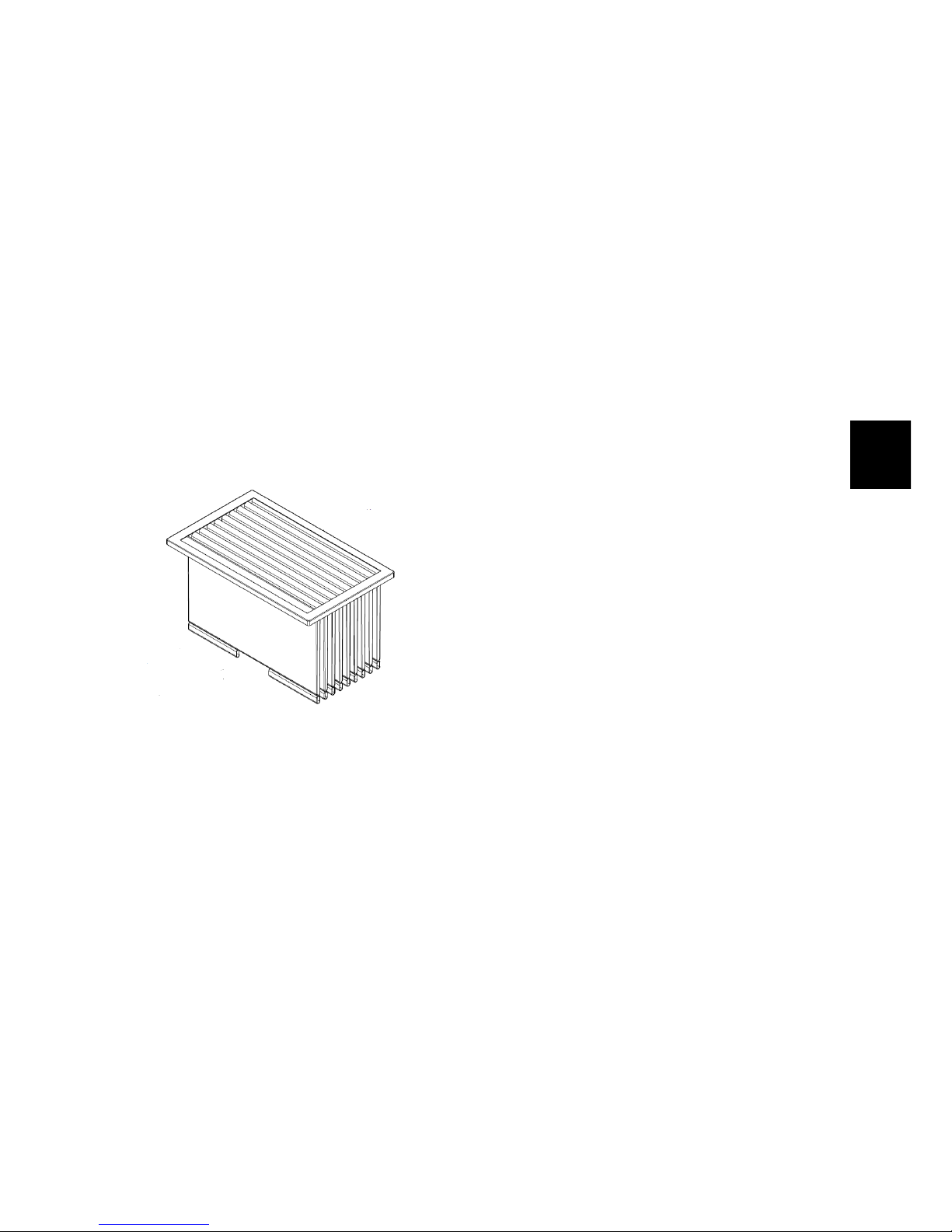
8-69
It should be used regularly (with variable interval depending on the floor conditions) and can be operated manually
by the operator.
While using the Filter Shaker, the suction is turned off.
In case of use of the machine on a wet
surface, the vacuum system must be
swtched off. This system in fact, as
stated at the beginning, is used to collect dust and, in the case of wet floor, the
powder is mixed with water on the floor,
and certainly does not need the vacuum
to be collected.
The aspiration can be disabled manually by the operator.
Figure 8.1: Cloth Filter
Figure 8.2: Panel Filter
Page 70

8-70
8.3 Adjustments
8.3.1 Front Flap
The front flap practically has no type of
adjustment, since the fixing screws of
the flap to the frame have a unique possibility of fixing, as well as the flap rubber.
8.3.2 Rear Flap
The rear flap can be adjusted by means
of the slots in the rubber. The rear flap
must be adjusted in order to let the rubber be at 2mm from the ground.
8.3.3 Side Flap
The side flap can be adjusted by means
of the slots in the rubber. The side flap
must be adjusted in order to let the rubber be at 2mm from the ground.
8.3.3-1 Front Flap 8.3.3-2 Rear Flap
8.3.3-3 Side Flap
8.4 Maintenance and
Checks
8.4.1 Front Flap
Check (to perform every 150h)
The front flap has to be flexible and
should be very close to the ground. By
using its pedal, the flap must be free to
move. It doesn’t have to show visible
signs of wear or damage. Check the
integrity of the flap and if it is necessary
proceed to replace it.
8.4.2 Rear and Side Flap
Check (to perform every 150h)
The Rear and Side flaps have to be
flexible and should be very close to the
ground. They doesn’t have to show visible signs of wear or damage. Check the
integrity of the flap and if it is necessary
proceed to replace it.
8.4.3 Vacuum Motor
Check (to perform every 150h)
In standard working conditions, the
motor has a power consumption of
about 20 Amps. Verify that this value
is respected and verify that the motor
is always clean. Check the integrity
and size of the carbon brushes, and if
necessary replace them.
Maintenance (to perform every 600h)
Motor carbon brushes replacement: Procedure:
• Put the machine in safe conditions.
• Lift the upper body / seat.
• Disconnect the battery connector.
• Loosen the screws that secure the
collar brush guard.
Page 71

8-71
• Disconnect the Carbon brushes
from the input power line to the motor.
• Replace the carbon brushes being
careful not to ruin them during assembly.
• Proceed to the reverse operations to
reassemble it all.
8.4.4 Vacuum Filter
Check (to perform every 4h)
Make sure the filter is intact and has no
cracks or visible damage. Verify, with
machine totally in operation, that the
air discharged by the vacuum system is
clean and contain no dust.
Maintenance (to perform every 4h)
Proceed thorough an accurate inspection and cleaning of the filter by blowing
it, and in the case of cloth filter also to a
possible washing. If necessary proceed
to replace it (see section 4.4.3 at page 28).
8.4.5 Filter shaker
Check (to perform every 150h)
Check the correct operation of the filter
shaker and the integrity of its supports.
Verify that the absorption of filter shaker
is about 3.6 Amps.
Page 72

8-72
8.5 Technical Features
TECHNICAL DESCRIPTION U/M FSR B FSR Hybrid
Vacuum Motor Voltage V 24 24
Filter shaker Voltage V 24 24
Vacuum Motor Power W 400 400
Filter shaker Power W 80 80
Filtration area (Panel filter) m
2
3.2 3.2
Filtration area (Cloth filter) m
2
2.2 2.2
8.6 Consumable Spare Parts
FSR
PN Description B Hybrid
438293 FRONT FLAP RUBBER
√ √
437880 REAR FLAP RUBBER
√ √
437882 LEFT SIDE FLAP RUBBER
√ √
437881 RIGHT SIDE FLAP RUBBER
√ √
411675 PANEL FILTER
√ √
Carbon Brushes
415982 VAC.MOT.CARBON BR.
√ √
8.7 Recommended Spare Parts
FSR
PN Description B Hybrid
223685 MOTOR MP80S/2 24V 2300G 400W + CONN.
√ √
223686 FILTER SHAKER MP50 W80 V24 + CONN.
√ √
416388 VACUUM FAN D.230
√ √
Page 73

9-73
Chapter 9
Collection System
9.1 Structure
1. Debris Hopper
9.2 Description
The function of the collection system is
to collect the dirt removed from the floor
and to facilitate the discharge.
The debris hopper (the main part of the
collection system) can be both front and
rear. This hopper can be moved automatically or manually according to the
type of machine where it is mounted.
In the FSR the debris hopper is rear and
is manually operated.
73
Page 74
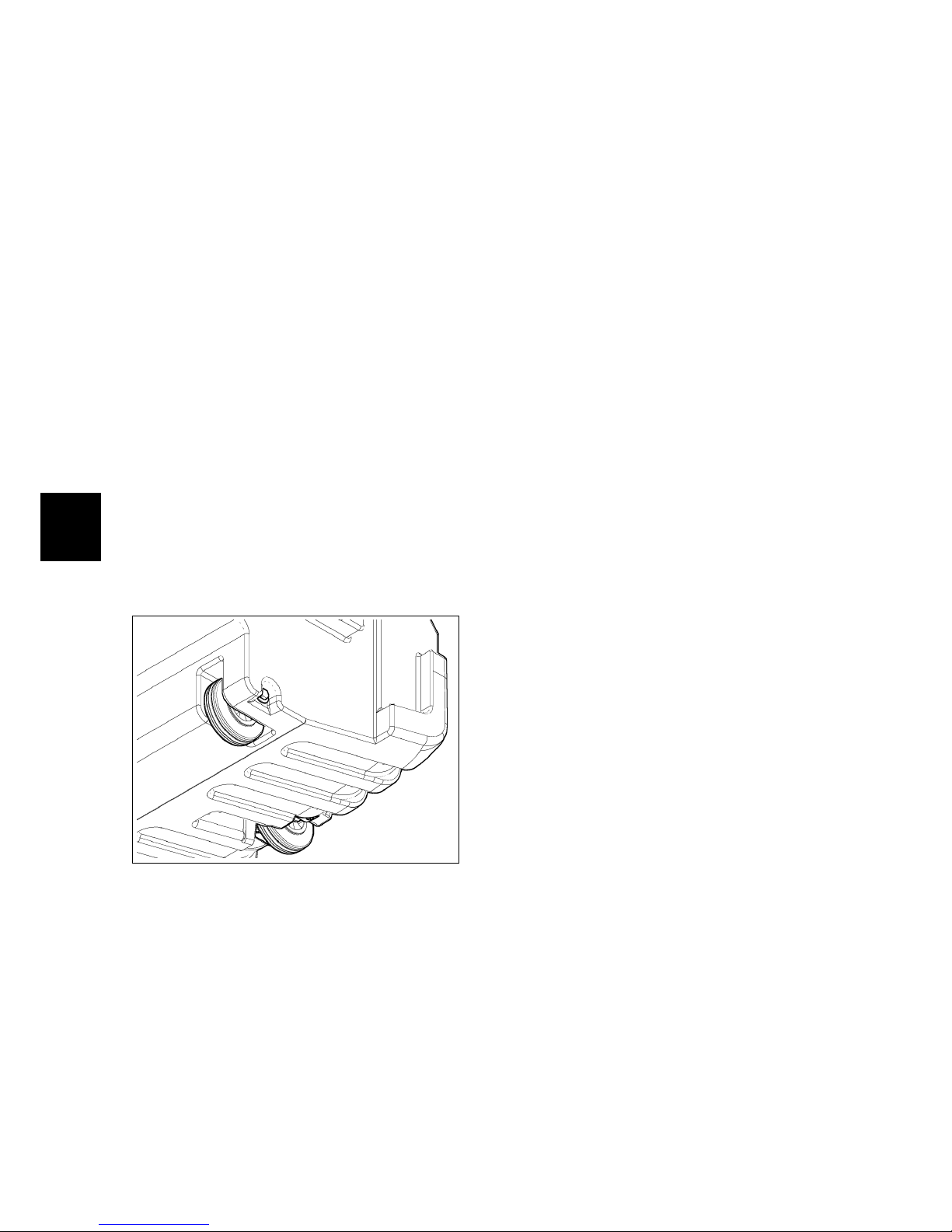
9-74
9.3 Maintenance and
Checks
9.3.1 Debris Hopper
Check (to perform every 150h)
The debris hopper must be kept clean.
It is important to verify its integrity so
that there are no leaks of pressure or
loss of residues during work or transfer.
9.3.2 Wheels
Check (to perform every 150h)
The wheels must be intact and perfectly
functioning in order to allow the correct
movement of the debris hopper.
Maintenance (to perform every 600h)
The wheels should be checked and when
the tread is no longer visible they must
be replaced (see section 4.4.5 at page 29).
Page 75

9-75
9.4 Technical Features
TECHNICAL DESCRIPTION U/M FSR B FSR Hybrid
Debris Hopper Volume dm320 20
Hopper Material - LLDPE LLDPE
Handling system - Manual Manual
9.5 Consumable Spare Parts
FSR
PN Description B Hybrid
437904 BUSHING D=25-12 d=8 S=23 S235
√ √
414313 WHEEL D=100X35-45 PM55
√ √
Page 76

10-76
Chapter 10
Machine Frame and Traction System
10.1 Structure
1. Main broom and side brush lever
system
2. Steering column
3. Front Wheel
4. Frame
5. Rear Wheels
6. Traction Motor
10.2 Description
The frame is a unique structure in
painted steel. On it are coupled the
steering system including the levers for
the activation of the main broom and the
side brush, and the traction system.
The steering system is composed by a
steering column connected to a steering
wheel , which acts directly on the front
wheel . The steering is ensured by a pinion and a crown, connected by a chain.
The pinion is welded directly onto the
steering, while the crown is installed on
the assembly front wheel.
On top of the steering column, there
are the levers for the activation of the
main broom and the side brush. To ensure the proper functioning of the two
brush types, in the steering column are
installed some microswitches that act directly on the affected systems.
The traction of the machine is guaranteed by an electric motor installed in
combination with a gear, whose output
shafts act directly on the rear wheels of
the machine, ensuring traction.
The gear motor is equipped with an
electrobrake which ensures the immobility of the machine when it is not moving.
Both the front wheel the rear wheels are
non-marking and antiskid.
76
Page 77

10-77
10.3 Adjustments
10.3.1 Steering wheel
The steering wheel should be adjusted
when there is too much clearance between the chain that acts on the pinion connected to the steering bar of the
steering wheel and the crown mounted
on the front wheel.
Procedure
• Put the machine in safe conditions.
• Remove the steering wheel cover.
• Loosen the nuts securing the bottom
support plate of the steering shaft.
• Release the grains locking nuts, set
the optimum tension of the chain by
acting on the grains, lock the adjustment by tightening the locking nuts.
• Once found the optimum tension
retighten the fixing nuts to lock the
bottom supporting plate of the steering shaft.
• Restore the steering wheel cover.
10.3.1-4 Steering adjustment
10.3.1-5 Steering adjustment
10.4 Maintenance and
Checks
10.4.1 Levers
Check (to perform every 150h)
The operating levers of the main broom
and the side brush, must always be operated with ease and without excessive
effort from the operator.
Maintenance (to perform every 600h)
Replacement of the brass laminated
bushings:
• Put the machine in safe conditions.
• Remove the steering wheel cover.
• Lower the main broom and the side
brush.
• Unscrew the screws that hold the
levers to the steering column and remove the internal levers.
• Proceed with the removal of the
bushings and replace them with new
bushings.
• Restore the steering wheel cover.
10.4.1-6 Bushings Replacement
10.4.1-7 Bushings Replacement
Page 78

10-78
10.4.2 Steering
Check (to perform every 150h)
The steering must always be precise and
free to rotate smoothly. Check that the
ring and the pinion coupling chain has
no excessive clearance and is not noisy.
Maintenance (to perform every 600h)
Periodically grease the ring and pinion
coupling chain. If the chain is too loose,
adjust the chain tension as described in
the ”Settings” paragraph.
10.4.2-8 Steering system
10.4.3 Front Wheel
Check (to perform every 150h)
The wheel must be free to rotate
smoothly without friction. The wheel
surface, must always be in good condition.
10.4.4 Rear Wheels
Check (to perform every 150h)
The wheel surface, must always be in
good condition.
Maintenance (to perform every 600h)
Periodically check the wheel bearings
status. Periodically grease the wheel
bearings.
10.4.5 Traction motor
Check (to perform every 150h)
During normal running, the current
consumption must be between 5 and 7
Amps.
ATTENTION – At the start the absorption
current of the motor is much higher.
The carbon brushes of the traction motor drive must be at least 6-8 mm long.
The isolation of the power cables of the
motor and the electrobrake, must be
complete in all their parts and do not
show signs of cracks. The cables must
demonstrate flexibility. The activation
lever of the electrobrake should activate
only if a certain push is applied.
• With electrobrake engaged and the
machine not powered, the machine
itself should not move.
• With electrobrake engaged and the
machine powered but not moving,
the machine itself should not move.
• With electrobrake engaged, when
acting the traction, the machine itself have to move.
Lifting the machine to make the rear
wheels neutral, by spinning a wheel (in
any sense) the other should turn in the
opposite direction.
Maintenance (to perform every 600h)
Motor carbon brushes replacement: Procedure:
• Put the machine in safe conditions.
• Remove the traction group from the
machine (see section 4.5.4 at page 30).
• Mark the correct positioning of the
motor hood before proceeding in the
operation.
• Remove the plastic side covers and
unscrew the screws that secure the
hood to the motor (see fig. 10.4.5-10),(see fig.
10.4.5-11).
Page 79

10-79
10.4.5-9 Motor Hood Positioning
10.4.5-10 Side Covers
• Remove the connectors that fix the
carbon brushes to the mains supply
and remove the carbon brushes from
the body of the hood (do not miss the
compensating ring) (see fig. 10.4.5-12).
10.4.5-11 Fixing screws 10.4.5-12 Carbon brushes
removal
• Replace the carbon brushes being
careful not to ruin them during assembly.
• Proceed to the reverse operations to
reassemble everything.
Page 80

10-80
10.5 Technical Features
TECHNICAL DESCRIPTION U/M FSR B FSR Hybrid
Traction motor Voltage V 24 24
Traction motor Power W 300 300
Traction wheel (diam/width) Ømm/mm 175/60 175/60
Front Wheel material Polyurethane Polyurethane
Front Wheel hardness Sh 85 85
Rear Wheel (diam/width) Ømm/mm 225/69 230/88
Rear Wheel material Polyurethane Pneumatic Rubber
Rear Wheel hardness Sh 85
Rear Wheel pressure bar 3.5
Maximum forward speed Km/h 4.8 4.8
Maximum reverse speed Km/h 2.8 2.8
10.6 Consumable spare parts
FSR
PN Description B Hybrid
436222 FRONT WHEEL D=175 d=20 S=60 WITH BEARINGS
√ √
426460 REAR WHEEL D=225 L=69
√
437947 PNEUMATIC REAR WHEEL D=230 L=88
√
Carbon Brushes
422462 TR. MOTOR CARBON BRUSHES
√ √
10.7 Recommended Spare Parts
FSR
PN Description B Hybrid
222454 TRACTION MOTOR 24V 300W 115G 18A EL.BR.+ MOLEX
√ √
Page 81

11-81
Chapter 11
Endothermic engine (FSR Hybrid)
Figure 11.1: Endothermic Engine
11.1 Structure
1. Description
2. Operation of the Hybrid Model
3. Endothermic Engine Components
4. Maintenance and Checks
11.2 Description
The FSR Hybrid model is equipped with
an internal combustion engine powered
by gasoline.
The endothermic engine is connected
to an alternator so that, during gasoline
operation, the on board batteries of the
machine are properly recharged.
At the same time, always while operating with gasoline, the alternator has the
task to provide adequate power supply to
ensure the proper operation of the drive
motor, vacuum motor, filter shaker motor and brushes motor.
It is possible to alternate working cycles on battery power to working cycles
with power combustion engine.
The operator can easily select the power
supply mode using the main switch
(key).
FSR is designed to provide maximum
efficiency in working condition and
then whenever the power from the
endothermic engine was shut down by
the end of the fuel the sweeper machine
automatically comes to work on battery
power.
81
Page 82

11-82
11.3 Operation of the Hybrid Model
11.3.1 Operation with battery
power
To start the working cycle with battery
power is sufficient to turn the main
switch (key) in position I, the machine
will start the work cycle by using the
charge inside the battery installed on the
machine until exhausted of the available
charge.
11.3.1-1 Main Switch position I
11.3.2 Operation with Endothermic Engine
To start using the machine with power
supply from Endothermic engine, it is
necessary to:
• Turn the main switch (key) in position II (see fig. 11.3.2-2). On the machine’s display will appear ”START
ENGINE” (see fig. 11.3.2-3).
11.3.2-2 Main Switch position II
11.3.2-3 Display signal
• To start a cold engine, move the
choke lever to the CLOSED position.
• To restart a warm engine, leave the
choke lever to the OPEN position.
Figure 11.2: Choke lever
Page 83

11-83
• Move the throttle lever to the middle
position.
Figure 11.3: Throttle lever
• Pull the starter grip lightly until a
certain resistance, then pull vigorously. Bring gently to the original
position the starter handle. At this
point the internal combustion engine is in operation.
Figure 11.4: Starter Handle
• If the choke lever has been put into
the CLOSED position to start the engine, gradually move it to the OPEN
position while the engine warms up.
• Place the choke lever on the maximum speed possible in order to allow the proper charging of the batteries.
At this point it is possible to start to use
the machine for a normal working cycle.
Page 84

11-84
11.4 Endothermic Engine
The Endothermic engine is composed of:
1. Fuel Tank
2. Choke Lever
3. Fuel Valve Lever
4. Starter Grip
5. Engine Switch
6. Air Filter
7. Oil Filler Cap/Dipstick
8. Spark Plug
9. Muffler
10. Oil Drain Hose
11. Throttle Lever / Motor turns
Page 85

11-85
11.5 Maintenance and
Checks
11.5.1 Checks before operation
Before using the sweeper machine powered by endothermic engine, it is necessary to check the following (make sure
the engine is on a flat floor and that the
engine switch is in the OFF position):
• Look around and underneath the
engine for signs of oil or gasoline
leaks, and remove them with a dry
cloth.
• Remove any excessive dirt or debris,
especially around the muffler and
recoil starter.
• Check that all shields and covers are
in place, and all nuts, bolts, and
screws are tightened.
• Check the fuel level. Starting with a
full tank will help to eliminate or reduce operating interruptions for refueling.
• Check the engine oil level. Running
the engine with a low oil level can
cause engine damage.
• Check the air filter element. A dirty
air filter element will restrict air flow
to the carburetor, reducing engine
performance.
11.5.2 Periodical Checks
Good maintenance is essential for safe,
economical and troublefree operation.
The maintenance schedule applies to
normal operating conditions. If you operate your engine under severe conditions, such as sustained high-load or
high-temperature operation, or use in
unusually wet or dusty conditions, consult your servicing dealer for recommendations applicable to your individual
needs and use. For proper scheduling
of periodic maintenance refer to the use
and maintenance manual of the engine.
In particular, for a prolonged and correct
use of the engine it is necessary to take
some precautions:
• This engine is certified to operate on
unleaded gasoline with a pump octane rating of 86 or higher (a research octane rating of 91 or higher).
• Oil is a major factor affecting performance and service life. Use 4-stroke
automotive detergent oil that meets
or exceeds the requirements for API
service classification SJ or later (or
equivalent). SAE 10W-30 is recommended for general use.
• Check the engine oil level with the
engine stopped and in a level position. If the oil level is near or below
the lower limit mark on the dipstick,
fill with the recommended oil to the
upper limit mark. To Fill the oil level
tank pull out the level dipstick and
fill with recommended oil up to the
upper limit mark. Do not overfill.
Page 86

11-86
11.5.2-1 Oil Level check Step 1.
11.5.2-2 Oil Level check Step 2.
• From time to time and according to
scheduled maintenance table in the
endothermic engine manual, replace
the engine oil. Use the special drain
hose on the side of the engine to
drain the oil tank. To drain the oil
drain hose, remove the side protection ring, remove the hose from the
clip and drain the contents of the
tank by sliding the hose adjacent to
the main brush.
11.5.2-3 Oil Replacement
- Step 1.
11.5.2-4 Oil Replacement
- Step 2.
11.5.2-5 Oil Replacement
- Step 3.
11.5.2-6 Oil Replacement
- Step 4.
• A dirty air filter will restrict air flow
to the carburetor, reducing engine
performance. If the engine is operated in very dusty areas, clean the
air filter often. To clean the filter remove the protective wing nut and remove the black plastic cover. At this
point use a jet of air to properly clean
the filtering body.
11.5.2-7 Air Filter Cleaning - Step 1.
11.5.2-8 Air Filter Cleaning - Step 2.
11.5.2-9 Air Filter Cleaning - Step 3.
11.5.2-10 Air Filter
Cleaning - Step 4.
• Choose a spark plug with the correct
heat range for operating temperatures of the engine, as BP4ES (NGK)
and W14EP-U (DENSO). To check
the spark plug remove the side ring
of protection and remove the spark
plug cap. Measure the distance between the spark plug electrodes with
a wire feeler gauge. Correct the distance as necessary, carefully bending the side electrode. The distance
between the electrodes should be of
from 0,70 to 0,80 mm.
Page 87

11-87
11.5.2-11 Spark plug
check - Step 1.
11.5.2-12 Spark plug
check - Step 2.
11.6 Warnings
• Gasoline is highly flammable and explosive. Stop the engine and let it
cool before refueling.
• The engine releases carbon monoxide which is a toxic poisonous gas.
Do not operate in an enclosed area.
Page 88

11-88
11.7 Technical Features
TECHNICAL DESCRIPTION U/M FSR Hybrid
Engine Dimensions (L x w x h) mm 319 x 343 x 333
Dry mass (weight) kg 18.6
Engine type 4 stroke single cylinder
Displacement cm3163
Net power kW 3,6 at 3.600 rpm
Tank Fuel Capacity l 3,1
Engine Oil Capacity l 0,6
Cooling system Forced air
Page 89

11-89
Part IV
Accessories and Add-On
89
Page 90

12-90
Chapter 12
Accessories
12.1 Accessories List
• Blinking Kit
• Onboard Charger Kit
12.2 Blinking Kit - 223421
12.2.1 Description
The kit consists of a alarmflashing yellow light. Although this light is not considered mandatory by law, if the user requires it for their particular needs is possible to equip the machine with this accessory.
12.2.2 Installing instructions
• Unplug the power cable of the batteries.
• Place the rubber circular base provided with the kit at the predisposition on the present on top of the
rear body as shown in the following
image.
12.2.2-13
• Place the blinker on the rubber
base so as shown in the figure so
as to match between rubber base
and body of the blinker the three
holes for the fixing screws crosswise
(screws M3x16).
• Drill the appropriate holes for the
three screws.
• Drill a similar central hole for the
passage of the power cable (the hole
must have be diameter 6). Final Result (see fig. 12.2.2-14).
12.2.2-14
• Pass the power cord into the diameter 6 hole and tighten the two power
contacts to the body of the blinker.
• Secure to the rear body, the blinker
and rubber base using the 3 screws
and 3 nuts supplied with the kit.
90
Page 91

12-91
12.2.2-15
• Connect the power cord connector of
the blinker to the electrical system
connector inside the rear body.
• Reconnect the battery cables and
proceed to a functional check of the
machine.
12.2.2-16
Page 92

12-92
12.3 Onboard Charger
Kit (only FSR B) 223390
12.3.1 Description
The machine is available in ”CB” version which is the version with the built
in charger. Anyway, in a standard machine, the battery charger can be fitted
acting as follows.
12.3.2 Machine Preparation
Before to start the kit installation is
mandatory to put the machine in safe
condition. Switch off the machine and
unplug the batteries.
12.3.3 Installing instructions
• To properly install the Battery
Charger remove from the rear compartment the vacuum motor, the filter and the filter shaker.
12.3.3-17 12.3.3-18
• Remove the screws in the clamp inserts in which will be fitted the support plate of the charger. Use the
screws and spacers provided in the
kit to secure the mounting plate.
• Attach the support plate using the
screws and spacers provided in the
kit. The slotted holes will be used
for the support of the charger and
the remaining holes for fixing the
bracket to the frame machine.
12.3.3-19 Battery charger
support bracket
12.3.3-20 Battery charger
fixing holes
12.3.3-21 fixing holes to
the machine frame
12.3.3-22 Spacer
• Attach the charger to the mounting
plate using the 4 screws supplied
with the kit and secure the wiring.
12.3.3-23 12.3.3-24
Page 93

12-93
Fimap S.p.A.
Workshop Handbook FSR
Fimap S.p.A. Via Invalidi del Lavoro, 1 - 37050 S.Maria di Zevio Verona - ITALY
Tel. +39 045 6060411 - Fax +39 045 6060417
Edizione: February 11, 2014
 Loading...