

Page 1

P-Series Umbrella Installation Instructions
These instructions are provided to facilitate assembly of the CAPRI umbrella, and for your safety.
¾
Please follow the instructions carefully.
¾
Failure to do so may result in damage to objects or injury to people. If in doubt, always consult an expert.
¾
Keep this handbook for future reference.
¾
IMPORTANT SAFETY INSTRUCTIONS
1. INSTRUCTIONS - Please completely read and follow all the instructions. Damage or injuries may
result if the umbrella is not assembled and used as described
herein. For safe use it is essential that anyone using the umbrella should have read all the
instructions in advance. Only persons familiar with
all safety aspects should operate this umbrella.
2. PRECAUTIONS - The CAPRI umbrella is intended for sun protection, not as protection from all
bad weather. It must be closed and removed from the frame in case of strong
winds or storms, as well as heavy rain or snow. Always close and remove the umbrella from the
frame at night, when you are not at home
and whenever it is not under control. The base must be ballasted with a minimum weight of 100 kg
(200 lbs). Always remove the handle from
the winch and keep it out of children's reach.
ASSEMBLY INSTRUCTIONS
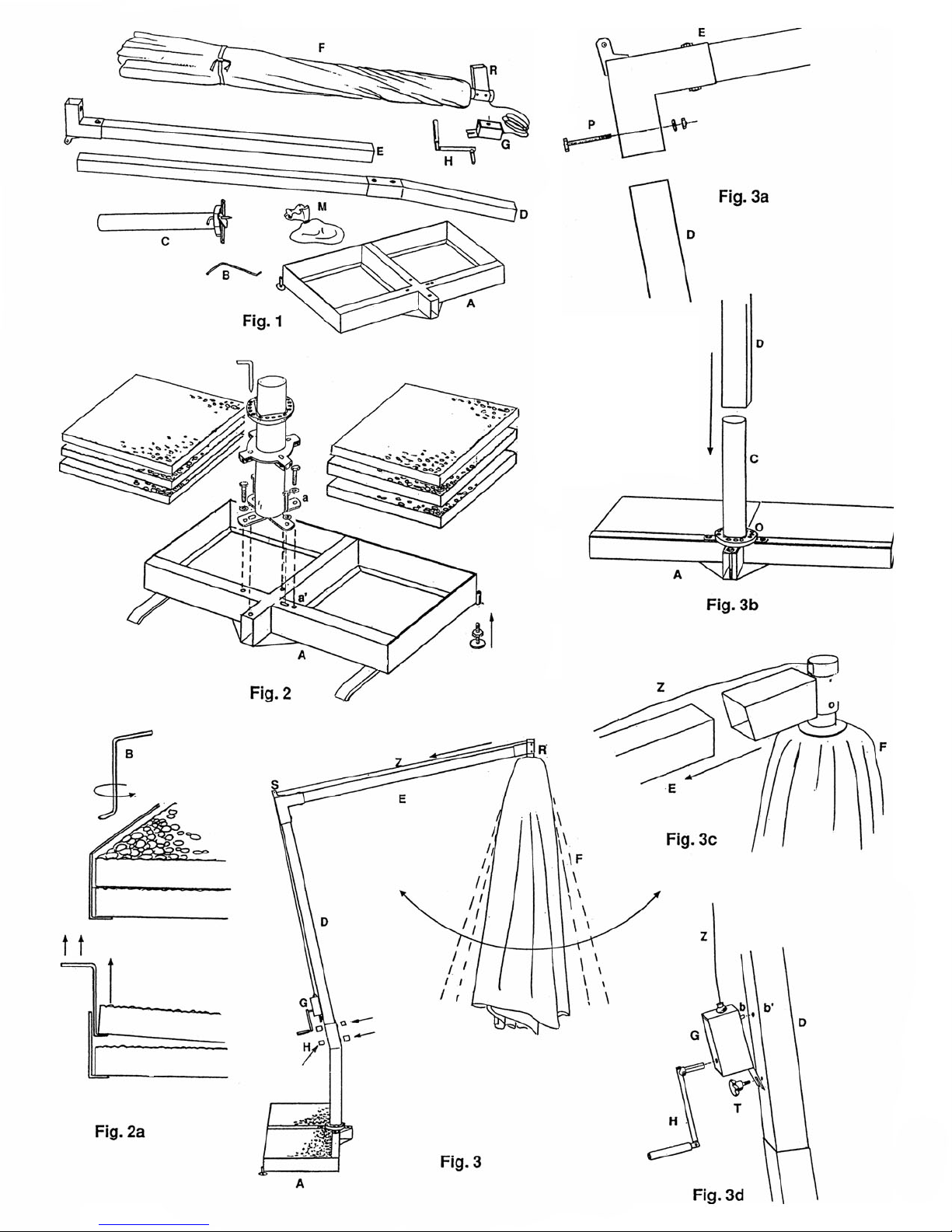
COMPONENTS (fig. 1):
G: winch - H: handle - I: clamps
M: bag with mounting accessories.
BASE ASSEMBLY (fig. 2 - fig. 2 a):
using the hook (B). The 2 adjustment screws (K) allow leveling
of the base (A). IMPORTANT: always fix the 2 feet (I) at the base (A).
CAUTION:
FRAME ASSEMBLY (fig. 3 - fig.3a - fig. 3b - fig. 3c - fig. 3d – fig. 4):
(fig 3a) insert the cantilever pole (E) into the vertical pole (D) and fix the two parts with the bolts (P).
1.
CAUTION
(fig 3b) Slide the vertical pole (D) over the base pole (C). IMPORTANT: the vertical pole (D) must be
2.
pushed down all the way into the square housing of the
orientation ring (O).
(fig. 3c) take the umbrella (F) and slide the umbrella attachment (R) over the cantilever pole (E).
3.
CAUTION
(fig.3) pass the cord (Z) over the pulley (S).
4.
(fig. 3d) screw in the handwheel (T) into the threaded hole of the vertical pole (D).
5.
insert the winch slot (G) onto the hand wheel (T). Next insert the winch (G) pin (b) into the hole (b') of the
6.
vertical pole (D)
and screw the hand wheel (T) well in.
insert the handle (H) into the hole of the winch (G).
7.
(fig. 3) put the 4 cover caps (N) onto the nuts.
8.
Your umbrella is now ready for use.
tighten the base bolts well. and ballast the base with a weight of at least 200 kg (400 lbs).
: tighten the bolts (P) well.
: the umbrella attachment (R) must be pushed in all the way onto the cantilever pole (E).
A: base - B: hook - C: base tube - D: vertical pole - E: cantilever pole - F: umbrella -
assemble the base as shown in fig 2 - place the four slabs in the base
Page 2

HOW TO USE YOUR UMBRELLA
OPENING THE UMBRELLA (fig.3 - 5)
IMPORTANT: before opening the umbrella remove the tie string and, by pulling the ribs with your hands,
slightly open the umbrella.
To open the umbrella, gently turn the handle (H) of the winch (G) clockwise, taking care not to force the
mechanism.
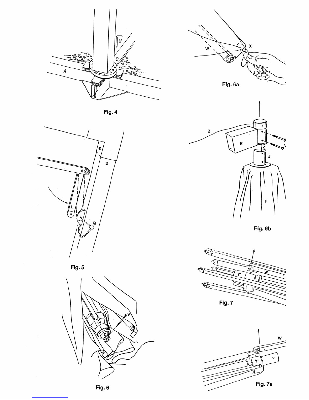
IMPORTANT: (fig. 5) after having opened the umbrella, connect the short stabilizer (L) to its fitting on the
frame, using the locking pin (Q).
IMPORTANT: (fig.5a) insert the cord (Z’) into the cleat (L’). This prevents accidental closing of the umbrella.
ROTATION OF THE UMBRELLA AROUND THE BASE (fig. 4):
(fig. 4) the frame can rotate 360º around the base and can be fixed in 12 different positions by inserting the
pin (U) into the adjustment ring (O).
REMOVAL OF THE UMBRELLA FROM THE FRAME (fig. 3 – 3d -5 – 5a):
IMPORTANTE: (fig. 5) to avoid damage, release stabilizer rib (L) from the fitting on the frame.
(fig.5a) remove the cord (Z’) from the cleat (L’).
1.
(fig. 3) close the umbrella by turning the handle (H) counter clockwise.
2.
. (fig. 3 – 3d) loosen the hand wheel (T), remove the winch (G) from the vertical pole (D) and remove the
3
rope (Z) from the pulley (S).
(fig. 3) remove the umbrella (F) from the frame by sliding the attachment (R) off the cantilever pole (E).
4.
MAINTENANCE AND CARE
REMOVAL OF THE WINCH AND THE FABRIC COVER OF THE UMBRELLA (fig. 6 - 6a - 6b):
(fig. 6) unscrew screw (V) to free the rope (Z).
1.
(fig. 6a) unscrew the screws (V’’) and release the grommet tabs (X) from the ribs (W).
2.
(fig. 6b) remove the screws (V') from the umbrella attachment (R).
3.
remove the umbrella attachment (R) from the umbrella pole (J).
4.
remove the rope (Z) from the umbrella pole (J) and from the umbrella attachment (R); in this way you can
5.
remove the winch (G)
from the umbrella (fig. 6b).
remove the cover from the umbrella pole (J).
6.
CHANGING A RIB (Fig.6a, 7, 7a):
(fig. 6a) unscrew the screw (V’’) and release the grommet tab (X) from the rib (W).
1.
(fig. 7) release the rib (W) to be exchanged from the lower hub(Y’) by pulling forcefully upwards.
2.
(fig. 7a) rotate the rib by 180° and release the other end from the upper hub(Y’’) by pulling forcefully
3.
upwards.
exchange the rib and repeat the operations described above in reverse order
4.
WASHING THE COVER:
remove the cover from the umbrella.
1.
hand wash the cover in tepid water - about 30º C (90º F) - with a mild detergent.
2.
dry the cover, but do not tumble dry or iron it.
3.
place the cover on the frame.
4.
STORING THE UMBRELLA AT THE END OF THE SEASON:
At the end of the season, before storing your CAPRI away, clean the frame with a damp cloth and dry it.
CAUTION
where it was purchased and order the required spare parts.
Touch up any possibly chipped paint.
For perfect conservation of the CAPRI during the winter months it is advisable to only store it in a dry place.
IMPORTANT: to avoid damage caused by mildew or oxidation never put your CAPRI away when wet or
damp.
: check the integrity of all the components. Should any part be damaged contact the dealer
READ THIS HANDBOOK IMMEDIATELY GB
Page 3
Page 4
Page 5

Call toll-free at 1-888-551-5221 with any questions
DECK MOUNT PLATE - INSTALLATION
HARDWARE AND TOOLS REQUIRED:
on wooden sundecks
⇒
Drill with ¼” drill bit
•
2 galvanized lag screws 3/8” x 4”, 2 galvanized lag screws 3/8” x 2 1/2”, 4
•
galvanized washers 3/8”
Ratchet with ½” socket
•
INSTALLATION PROCEDURE:
Place plate on the deck with 2 of the mounting holes centered over a deck
•
joist. Mark all 4 holes and pre-drill with the ¼” bit. (See enclosed drawing for
details)
Use the 4” lag screws to fasten the plate through the decking into the joist. It
•
may be helpful to lubricate the screws before inserting them.
Use the 2 1/2” lag screws to fasten the plate to the 2x4 or 2x6 running
•
perpendicular to the joist. On decks accessible from underneath, it is
preferable to use 3/8” x 3” hex bolts with a nut and large washer below the
deck.
IMPORTANT: Tighten the screws well, but to not use excessive force. On new
•
(green) sundecks, occasional re-tightening may be required due to shrinkage
of the lumber.
HARDWARE AND TOOLS REQUIRED:
on concrete patios
⇒
Hammer drill (e.g. Hilti) with ½” concrete bit
•
4 concrete spread anchors, 4 3/8” x 2” mounting bolts with washers. Consult
•
with your building supply specialist for proper combination of anchors and
bolts to achieve a minimum pullout strength of 200 lbs. per anchor.
Ratchet with ½” socket
•
INSTALLATION PROCEDURE:
Place plate on the concrete making sure it is not tipping or riding on a high
•
spot. Check plate with a level, shim if necessary.
Mark fastening holes, drill to proper depth.
•
Fasten plate with bolts into anchors
•
Page 6
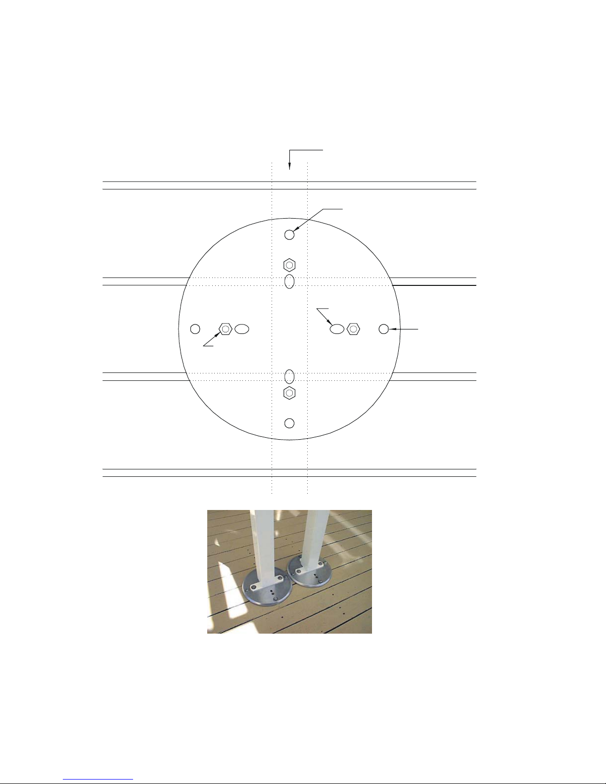
Deckmount Plate - correct placement
Deck Joist
3 1/2" Lag Bolts
Locking Pin
2 1/2" Lag Bolts
Suppo rt Tube
mounting hole
Page 7

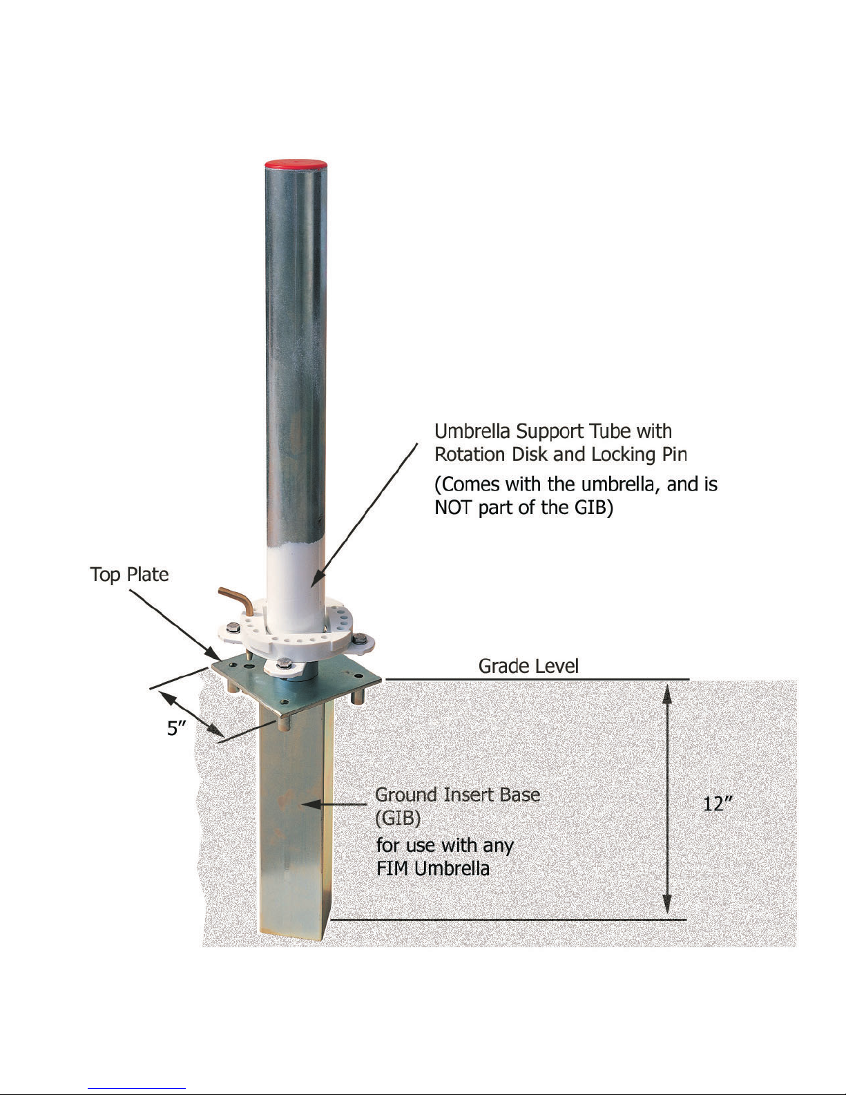
GROUND INSERT BASE - INSTALLATION
MATERIALS AND TOOLS REQUIRED:
1-2 bags of quick set ready mix concrete (please consult with your building supply
store for exact quantity)
2 gallon mixing bucket
small hand shovel or trowel
1 piece of 2x6, 18-20” long
2 - 4” C-clamps
Carpenters Level
INSTALLATION PROCEDURE:
1. Clamp the ground insert base with the flat top plate to the center of the 2x6
2. Determine exact location for the umbrella base.
3. VERY IMPORTANT: The umbrella rotation disk ‘O’ allows for a number of
fixed positions in a full 360º Circle. If you need to position and lock the
umbrella over an exact spot (e.g. the center of a table), make sure to
orient the ground insert sleeve so it allows you to properly lock the
umbrella in place with the locking pin ‘U’ at that specific location.
4. Once the proper location and orientation for the base have been established,
prepare a hole approximately 10x10" square and 18" deep, and fill it with quick-set
ready-mix concrete (Sakrete) to about 1" below the surface level. Make sure to
follow the mixing instructions carefully.
5. Push the ground sleeve into the mixture and agitate it with quick, short strokes it so
the concrete will bond to the metal. Lower the sleeve until the 2x6 rests on the
ground surrounding the hole, suspending the sleeve in the concrete. This way it is
assured that the top of the plate is flush with the surrounding ground once the
concrete has set.
6. Take a water level to check if the top of the 2x6 is exactly level in all directions !
If it is not, simply use shims or wedges to raise the board where necessary.
Complete this step carefully, as the umbrella post might appear to “lean” if the base
is not installed plumb.
7. Let the concrete set overnight. Remove the board and make sure not to knock the
sleeve hard (concrete takes up to 7 days to cure). Cover the open holes on top of
the base plate with masking tape.
8. Fill the remaining space around the top plate with some ready mix. (Do not fill the
1” space inside the tube – this space is required to fully insert the locking pin). Tap
the concrete in nicely, and finally drag your 2x6, held on edge, across the base with
a zigzag motion to smooth the surface. Let it sit for a few hours and then clean off
the top plate with a damp cloth. Make sure to let the concrete cure for at least 3
days in warm conditions, and up to 7 days if the temperature is below 50deg.
Fahrenheit /10deg. Celsius
FIM Manufacturing Inc. Toll-free phone: 888-551-5221
Page 8
 Loading...