

Page 1
L-ED
Conductive level indicator
for liquids
Operating
Instructions
Index
Safety instructions . . . . . . . . . . . . . . . . . . . . . . . . . . . . . . . . . . . . . . . . . . . . . . . . . . . . . . . . . . . . . . . . . . . . . . . . . . . . . . . . . . . 02
Operating instructions
1. Specification . . . . . . . . . . . . . . . . . . . . . . . . . . . . . . . . . . . . . . . . . . . . . . . . . . . . . . . . . . . . . . . . . . . . . . . . . . . . . . . . . . . . . . . 03
1.1 Intended use
1.2 Function
1.3 Technical data
1.4 Materials
1.5 Dimensions
2. Installation . . . . . . . . . . . . . . . . . . . . . . . . . . . . . . . . . . . . . . . . . . . . . . . . . . . . . . . . . . . . . . . . . . . . . . . . . . . . . . . . . . . . . . . . . 04
2.1 Preparing for use
2.2 Mechanical connection
2.3 Electrical connection
3. Use . . . . . . . . . . . . . . . . . . . . . . . . . . . . . . . . . . . . . . . . . . . . . . . . . . . . . . . . . . . . . . . . . . . . . . . . . . . . . . . . . . . . . . . . . . . . . . . 04
3.1 Commissioning
3.2 Normal operation
3.3 Inexpert handling
4. Maintenance, servicing and spare parts . . . . . . . . . . . . . . . . . . . . . . . . . . . . . . . . . . . . . . . . . . . . . . . . . . . . . . . . . . . . . . . . 04
4.1 Maintenance
4.2 Servicing
4.3 Spare parts
Page
5. Storage . . . . . . . . . . . . . . . . . . . . . . . . . . . . . . . . . . . . . . . . . . . . . . . . . . . . . . . . . . . . . . . . . . . . . . . . . . . . . . . . . . . . . . . . . . . . 04
6. Disposal . . . . . . . . . . . . . . . . . . . . . . . . . . . . . . . . . . . . . . . . . . . . . . . . . . . . . . . . . . . . . . . . . . . . . . . . . . . . . . . . . . . . . . . . . . 04
05/14 MI-LED-EN-01 © by FILSA
Talleres Filsa, S.A.U. www.filsa.es • • • • • E-08100 Mollet del Vallès (Barcelona) Tel. +34 93 570 46 01 Fax +34 93 570 24 71 [email protected] 01
Page 2
L-ED
Read these Safety instructions before using the switch for the first time and follow the Operating instructions.
Safety instructions
1. The installation, initial operation and maintenance should only be carried out by a qualified expert with electrical know-how.
2. Comply with the local and statutory rules and/or the VDE0100.
3. Before electrical connection, check the specifications on the data plate and the technical data of this manual.
4. A fuse must be connected in series to the supply voltage, according to the Standard and Normative documents.
5. Protect the signal contacts of the limit switch against voltage peaks when inductive or capacitive loads are connected.
6. The device may be put into operation only if the electrical connection is correct.
7. Switch off the power supply, before disconnecting the device.
05/14 MI-LED-EN-02 © by FILSA
02 Talleres Filsa, S.A.U. www.filsa.es• • • • • E-08100 Mollet del Vallès (Barcelona) Tel. +34 93 570 46 01 Fax +34 93 570 24 71 [email protected]
Page 3
Operating instructions
L-ED
1. Specification
1.1 Intended use
The conductive control level relay L-ED with the conductive probes
is used to control the level or to keep between 2 points the level of
conductive liquids like water, oil, chemical products, etc., in tanks
or recipients.
Conductive probes could be supplied under request, as well as the
undecal socket for the mounting in a DIN rail.
1.2 Function
The conductive level indicator L-ED bases its work in the
conductivity of the liquids to control. They have a level controllers
associated with a relay.
It is necessary an electrode or a probe for each level and a
common electrode. If the tank is conductive, it could be used as
the common electrode.
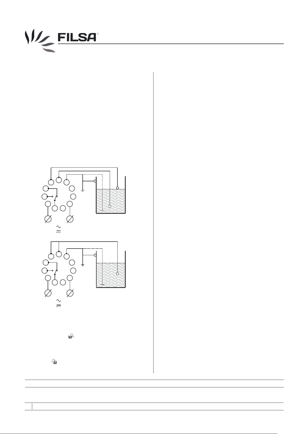
As shown in 2.3, to keep the level of liquid between two points, it is
necessary to connect the 2 probes and the common reference to
the L-ED.
If only an independent signal should be indicated, it would be
enough to place a probe in the desired point, as well as the
common and a jumper connection must be mounted between the
terminals (5) and (6).
The DC L-EDs (24 V DC and 12 V DC), are manufactured with a
built-in selector. Changing this selector position, allows to choose
the operation mode between filling and emptying, without
modifying the relay output’s connections.
1.3 Technical data
Manufacturer Talleres Filsa, S.A.U.
Address Bernat Metge, 33
Name Level control relay
Type L-ED ref: 2750-1-...
Suppyl voltage
2750-1-230 230 V AC (50 ... 60 Hz)
2750-1-115 115 V AC (50 ... 60 Hz)
2750-1-024 24 V AC (50 ... 60 Hz)
2750-1-024-DC 24 V DC
2750-1-012-DC 12 V DC
Power consumption
AC models 1.7 W
DC models 1.2 W
Maximum cable section Ø 1 ... 2.5 mm
Maximum cable length
AC models
DC models
Relay output AC mod. for load
Resistive AC 10 A / 250 V
Resistive DC 0.4 A / 200 V or 10 A / 24 V
Inductive AC 5 A / 250 V
Inductive DC 5 A / 24 V
08100 Mollet del Vallès
(Barcelona)
2
150 m, without shielding
100 m, without shielding
Relay output DC mod. for load
Resistive AC 10 A / 250 V
Resistive DC 0.4 A / 200 V or 10 A / 24 V
Inductive AC 5 A / 250 V
Inductive DC 5 A / 24 V
Function status Relay engaged: red LED
Under voltage: green LED
Ambient temperature -20 °C ... +50 °C
Relative humidity 30 % ... 85 %
Protection IP20 according DIN EN60529
Weight 0.18 kg
Current in probes line
AC models 4 mA
DC models 3.2 mA
Voltage in probes line
AC models 24 V AC
DC models 6.2 V AC
Insulation voltage 2.500 V AC
Insulation resistance >10 MÙ
Mechanical life 30x10 operations
Sensitivity
AC models 7 ... 100 kÙ
DC models 8 ... 45 kÙ
4
6
1.4 Materials
Housing Cycoloy
LED visor
Buttons Technyl
Terminals Brass
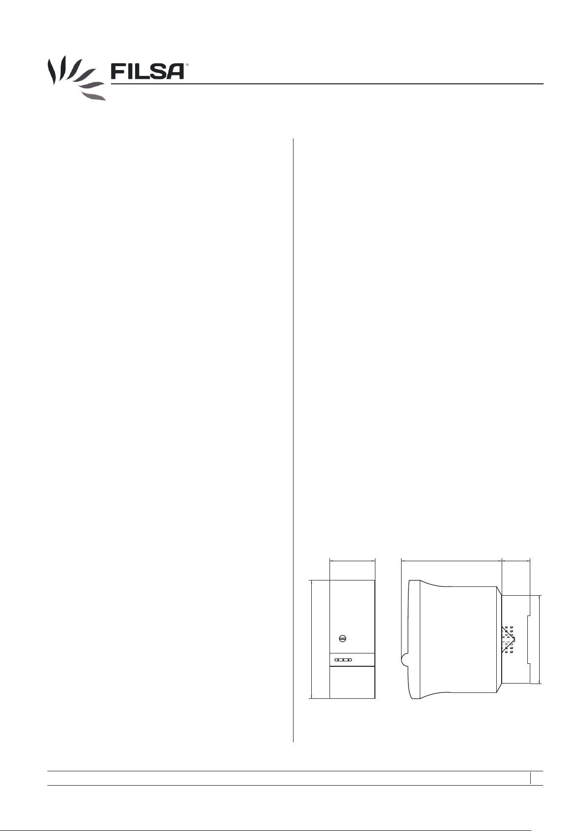
1.5 Dimensions
Approximate measures are given in mm.
35
91.5
Lexan
77
22
68
LED-001
05/14 MI-LED-EN-03 © by FILSA
Talleres Filsa, S.A.U. www.filsa.es • • • • • E-08100 Mollet del Vallès (Barcelona) Tel. +34 93 570 46 01 Fax +34 93 570 24 71 [email protected] 03
Page 4
L-ED
2. Installation
2.1 Preparing for use
Read the Safety Instructions and the Operating Instructions
before using the controller.
- Verify if you have got all the parts:
• Conductive control level relay.
• Conductive probes, if required.
• Undecal socket, if required.
2.2 Mechanical connection
It is simple: the device has to be installed in a DIN rail using the
undecal socket.
2.3 Electrical connection
Connection diagram
6
5
4
3
2
L
+
Example: control of a signal level
5
4
3
2
7
8
9
10
1
11
N
-
6
7
8
9
10
1
11
LED-001
3. Use
3.1 Commissioning
- Put the controller into operation only if the installation and the
electrical connection have been done correctly.
3.2 Normal operation
- Use the controller in its intended application only.
- Comply with the specifications
data of this manual.
- If the controller is damaged, disconnect it immediately.
- It is forbidden to make changes to the device. This violates the
Normative.
on the data plate and the technical
3.3 Inexpert handling
- Ignoring the Safety instructions and the Operating instructions.
- Not intended use.
- Making changes or handling the float switch.
- Violation against applicable Law and Standards.
- Using of non original parts.
4. Maintenance, servicing and spare parts
4.1 Maintenance
- If used correctly, no specific maintenance is required.
4.2 Servicing
- Check and review the state of the housing, the probes and the
correct commutation of the electrical contact, as well.
4.3 Spare parts
- There are no spare parts for these controllers.
5. Storage
- Store the controller in a dry and dust-free environment.
6. Disposal
Switch off the power supply, before disconnecting the device.
L
+
N
-
LED-002
Function in emptying
The relay operates when the liquid reaches the maximum level
electrode (5), and it releases when the liquid goes below the
minimum level (6). For the DC models the selector must be in the
emptying position ( ).
Function in filling
For the AC models, the relay’s output connections must be
modified .For the DC models, the selector must be in the filling
position ( ). The relay operates when the liquid level is below the
minimum electrode (6), and it releases when the liquid level is
above the maximum electrode (5).
FILSA constantly strives to improve its products and reserves the right to modify designs, materials and data without prior notice.
Keep this manual for further questions!
05/14 © by FILSA MI-LED-EN-04
04 Talleres Filsa, S.A.U. www.filsa.es• • • • • E-08100 Mollet del Vallès (Barcelona) Tel. +34 93 570 46 01 Fax +34 93 570 24 71 [email protected]
-
- The controller can be recycled.
- The disposal applies to the valid environmental Guidelines
according to the location of the carrier and the local
manufacturing conditions.
 Loading...