

Page 1
ILV-660
Vibrating level indicator
for solids
Operating
Instructions
Index
Safety instructions . . . . . . . . . . . . . . . . . . . . . . . . . . . . . . . . . . . . . . . . . . . . . . . . . . . . . . . . . . . . . . . . . . . . . . . . . . . . . . . . . . . 02
Operating instructions
1. Specification . . . . . . . . . . . . . . . . . . . . . . . . . . . . . . . . . . . . . . . . . . . . . . . . . . . . . . . . . . . . . . . . . . . . . . . . . . . . . . . . . . . . . . . 03
1.1 Intended use
1.2 Function
1.3 Technical data
1.4 Materials
1.5 Dimensions
2. Installation . . . . . . . . . . . . . . . . . . . . . . . . . . . . . . . . . . . . . . . . . . . . . . . . . . . . . . . . . . . . . . . . . . . . . . . . . . . . . . . . . . . . . . . . . 03
2.1 Preparing for use
2.2 Mechanical connection . . . . . . . . . . . . . . . . . . . . . . . . . . . . . . . . . . . . . . . . . . . . . . . . . . . . . . . . . . . . . . . . . . . . . . . . . . . 04
2.3 Electrical connection
3. Use . . . . . . . . . . . . . . . . . . . . . . . . . . . . . . . . . . . . . . . . . . . . . . . . . . . . . . . . . . . . . . . . . . . . . . . . . . . . . . . . . . . . . . . . . . . . . . . 04
3.1 Commissioning
3.2 Normal operation
3.3 Inexpert handling
4. Maintenance, servicing and spare parts . . . . . . . . . . . . . . . . . . . . . . . . . . . . . . . . . . . . . . . . . . . . . . . . . . . . . . . . . . . . . . . . 04
4.1 Maintenance
4.2 Servicing
4.3 Spare parts
Page
5. Storage . . . . . . . . . . . . . . . . . . . . . . . . . . . . . . . . . . . . . . . . . . . . . . . . . . . . . . . . . . . . . . . . . . . . . . . . . . . . . . . . . . . . . . . . . . . . 04
6. Disposal . . . . . . . . . . . . . . . . . . . . . . . . . . . . . . . . . . . . . . . . . . . . . . . . . . . . . . . . . . . . . . . . . . . . . . . . . . . . . . . . . . . . . . . . . . 04
10/15 MI-ILV660-EN-01 © by FILSA
Talleres Filsa, S.A.U. www.filsa.es • • • • • E-08100 Mollet del Vallès (Barcelona) Tel. +34 93 570 46 01 Fax +34 93 570 24 71 [email protected] 01
Page 2
ILV-660
Read these Safety instructions before using the device for the first time and follow the Operating instructions.
Safety instructions
1. The installation, initial operation and maintenance should only be carried out by a qualified expert with electrical know-how.
2. Comply with the local and statutory rules and/or the VDE0100.
3. Before electrical connection, check the specifications on the data plate and the technical data of this manual.
4. A fuse must be connected in series to the supply voltage, according to the Standard and Normative documents.
5. Protect the signal contacts of the limit switch against voltage peaks when inductive or capacitive loads are connected.
6. The device may be put into operation only if the electrical connection is correct. To secure the type of protection, the sealing cap and the gasket
must be placed correctly and the screw nut of the cable gland has to be fixed and fastened to the cable entry.
7. The earth connection of the device has to be installed in such a way that mechanical damage will be excluded.
8. The probe must not be hit by the filling stream. To avoid this, deflect the filling stream or install a deflection screen or a protection roof. It is also
recommended to install a protection roof when the controllers are used as empty-indicator or medium-indicator in silos where vaults could be formed
or where high loads above it could exist.
9. For a proper function, the device should be installed with a 20 º to 30 º slope from the horizontal onto the silo wall to to facilitate the flow of the
material and to prevent the material from remaining over the probe.
10. The most sensitive part of the controller is the probe, do not hit or deform the probe it, the device can become useless.
11. Switch off the power supply, before disconnecting the device.
10/15 MI-ILV660-EN-02 © by FILSA
02 Talleres Filsa, S.A.U. www.filsa.es• • • • • E-08100 Mollet del Vallès (Barcelona) Tel. +34 93 570 46 01 Fax +34 93 570 24 71 [email protected]
Page 3
Instrucciones de uso
ILV-660
1. Descripción
1.1 Indicaciones para su aplicación
The vibrating level indicator ILV-660 is to be used to control the
maximum or minimum level of bulk solids in silos or vessels.
It is recommended for dusty and powdery, granulated and grainy
bulk goods like dust, flour, grain, sand, plastic, etc.
bulk density from 0.05 t/m and a maximum grain size of 10 mm.
It is not recommended for sticky solids or products that have the
tendency to settle over the fork.
1.2 Funcionamiento
The probe must to be exposed to the material. The probe of these
controllers is activated to its resonant frequency by a piezoelectric
system. When the product covers the probe, the vibration is
dampened and the control unit reverses the signal.
When the product disappears from the fork, it returns to the normal
vibrating state and the signal turns to the initial position.
The device has a insensitive rod between the probe and the
proccess connection to avoid the possibility of settle of the product
over the probe up to 75 mm.
1.3 Technical data
Manufacturer Talleres Filsa, S.A.U.
Address Bernat Metge, 33
Name Vibrating level indicator
Type ILV-660 ref: 2190-0-600
Supply voltage 24 V DC ± 10 %
Power consumption
Density of the product From 0.05 t/m
Maximum pressure +10 bar
Cable entry DIN43650 connector
Transistor output PNP or NPN depending on the
Function status Relay enabled: red LED
Resonance frecuency 460 Hz
Response time
Detecting level 1 s
Starting vibrating 2 ... 5 s
Product temperature -20 °C ... +70 °C
Ambient temperature -20 °C ... +60 °C
Protection IP65 according DIN EN60529
Weight 0.73 kg
Max. load upon the probe 80 N
1.4 Materials
Housing and probe Stainless Steel 1.4301
3
08100 Mollet del Vallès
(Barcelona)
1 W
3
connection
350 mA / 24 V DC
with a minimum
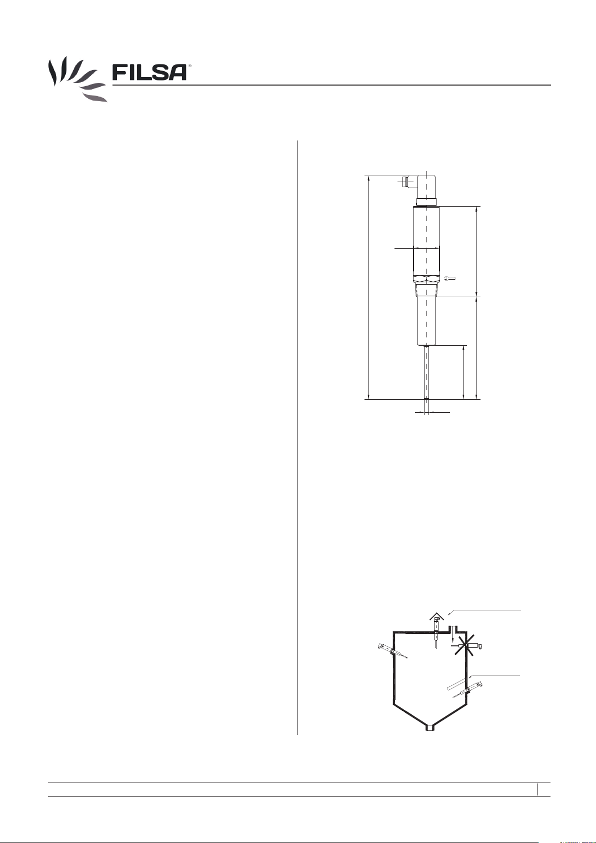
1.5 Dimensions
Approximate measures are given in mm.
LED
Ø 40
137
1 " tappered
340
DIN 2999
Probe
36
157
82
Ø 6.5
2. Installation
2.1 Preparing for use
Read the Safety instructions and the Operating instructions before
using the controller.
-
The probe must not be hit by the filling stream. To avoid this,
deflect the filling stream or install a deflection screen or a
protection roof. It is also recommended to install a protection roof
when the controllers are used as empty-indicator or mediumindicator in silos where vaults could be formed or where high
loads above it could exist.
For a proper function, the device should be installed with a 20 º to
-
30 º slope from the horizontal onto the silo wall to to facilitate the
flow of the material and to prevent the material from remaining
over the probe.
Weather protection
Protection roof
ILV660-001
ILV660-002
10/15 MI-ILV660-EN-03 © by FILSA
Talleres Filsa, S.A.U. www.filsa.es • • • • • E-08100 Mollet del Vallès (Barcelona) Tel. +34 93 570 46 01 Fax +34 93 570 24 71 [email protected] 03
Page 4
ILV-660
2.2 Mechanical connection
The device can be mounted horizontally or vertically depending on
the model.
The normal installation is by screwing the device onto the deposit
wall, with a mounting flange or
with an appropiate support to fix it.
2.3 Electrical connection
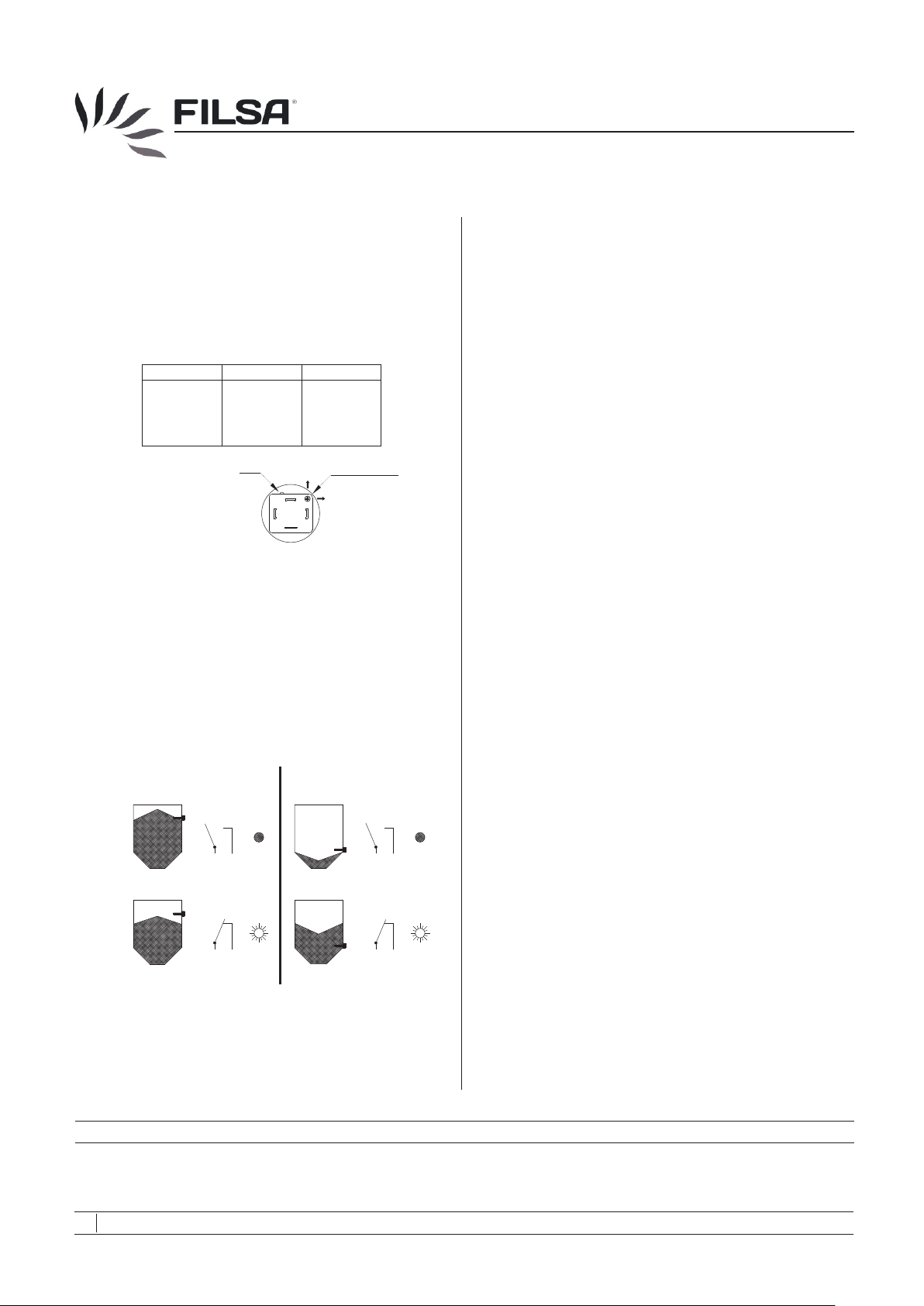
Connection diagram
Terminal
1
2
3
4
Level selector: To connect the device or the level selection
adjustment, take out the cap of the DIN connector and, if it is
necessary the sealing gasket. Turn the selector to detect high or
low level:
High level detection: Selector in position FSH. For high level
detection, the relay is disengaged when the probe is covered
of product or there is no supply. Red LED switched off.
Low level detection: Selector in position FSL. For low level
detection, the relay is disengaged when the probe is
uncovered of product or there is no supply. Red LED switched
off.
High level detection (FSH)
Deposit
Relay
PNP
+24 V DC = 3
+ of load
+24 V DC
[
LED
2
3
4
LED
NPN
- of load
= 4
[
+24 V DC
[
Level selector
FSH
FSL
1
Low level detection (FSL)
Deposit
Relay
ILV660-003
LED
3. Use
3.1 Commissioning
- Put the controller into operation only if the installation and the
electrical connection have been done correctly.
3.2 Normal operation
- Use the controller in its intended application only.
- Comply with the specifications
data of this manual.
- If the controller is damaged, disconnect it immediately.
- It is forbidden to make changes to the device. This violates the
Normative.
on the data plate and the technical
3.3 Inexpert handling
- Ignoring the Safety instructions and the Operating instructions.
- Not intended use.
- Making changes or handling the controller.
- Violation against applicable Law and Standards.
- Using of non original parts.
4. Maintenance, servicing and spare parts
4.1 Maintenance
- If used correctly, no specific maintenance is required.
4.2 Servicing
- Check and review the state of the housing, the probe and the
correct commutation of the electrical contact, as well.
4.3 Spare parts
- There are no spare parts for this controller.
5. Storage
- Store the controller in a dry and dust-free environment.
1 2
Full
1 2
Filling
DIN connector
- Fasten the DIN connector after making the electrical connection.
- Fix and fasten the screw of the DIN connector to ensure the
water-tightness.
FILSA constantly strives to improve its products and reserves the right to modify designs, materials and data without prior notice.
10/15 MI-ILV660-EN-04 © by FILSA
04 Talleres Filsa, S.A.U. www.filsa.es• • • • • E-08100 Mollet del Vallès (Barcelona) Tel. +34 93 570 46 01 Fax +34 93 570 24 71 [email protected]
Empty
Emptying
1 2
6. Disposal
Switch off the power supply, before disconnecting the device.
-
- The controller can be recycled.
1 2
ILV660-004
Keep this manual for further questions!
- The disposal applies to the valid environmental Guidelines
according to the location of the carrier and the local
manufacturing conditions.
 Loading...