

Page 1
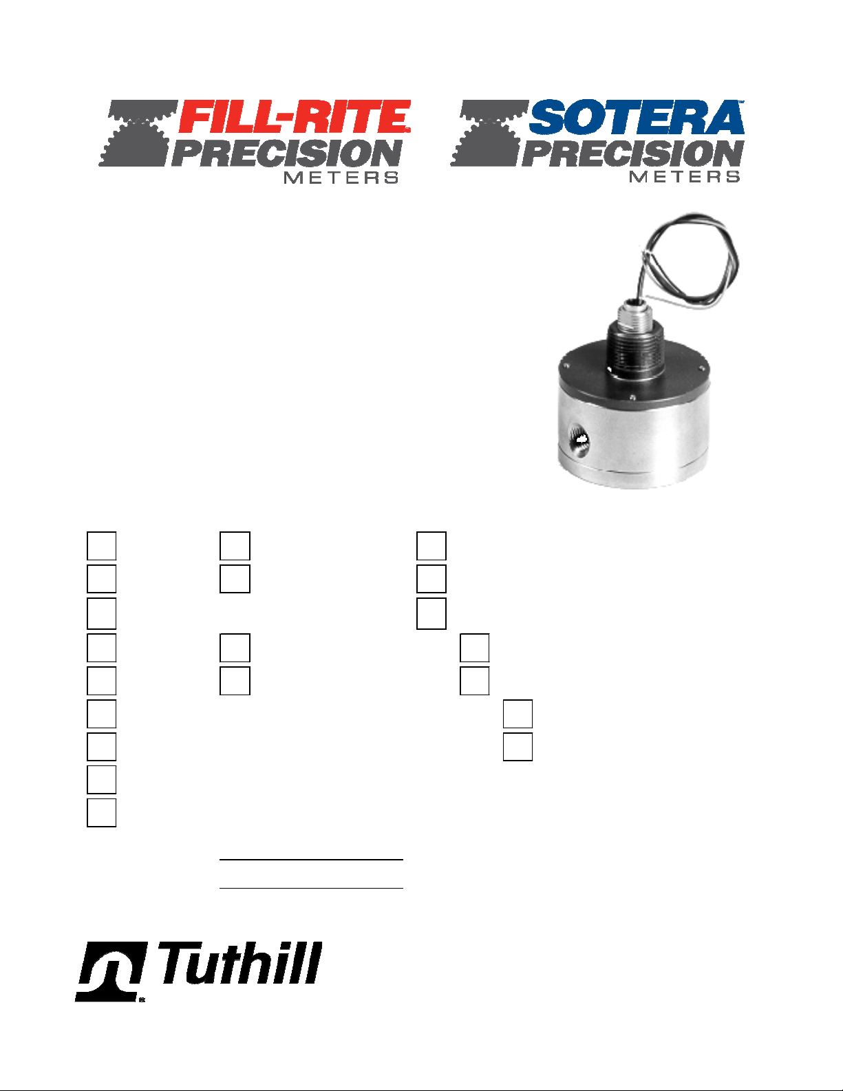
TM Series
Electronic
FPPMM001, Rev. 2012-03
Installation, Operation
& Parts Manual
MODEL Internal Pulser Register/Signal Conditioner
TM02D
TM03A
TM03D
TM04A
TM04C
TM04D
TM06A
TM06C
TM06D
Flow meter Part No.:
Flow meter Serial No.:
Hall Ef fect none
Reed Sw itch
Accessories
none Rem ot e
Strainer Installed
Regi st ers, Signal Condition ers and/ or Accessori es are su ppo rt ed with sep arat e
manuals, also supplied with the flow meter.
Signal conditioner
Register/Controller
NEMA 4X encl.
NEMA 7/4X encl.
: _____________
: _____________
Tuthill Transfer Systems,
8825 Aviation Drive, Fort Wayne IN 46809, USA
Tel: 260-747-9060 Fax: 800-866-4861 [email protected]
www.tuthill.com
Page 2

INDEX
About FPP Meters . . . . . . . . . . . . . . . . . . . . . . . . . . . . . . . . . . . . . . . . . . . 1 . 3
Principle of Operation . . . . . . . . . . . . . . . . . . . . . . . . . . . . . . . . . . . . . . . . 1 . 3
Fluid Compatibility . . . . . . . . . . . . . . . . . . . . . . . . . . . . . . . . . . . . . . . . . . . 1 . 3
Meter Specifications & Model Capacity . . . . . . . . . . . . . . . . . . . . . . . . . . 1 . 4
Safety Instructions . . . . . . . . . . . . . . . . . . . . . . . . . . . . . . . . . . . . . . . . . . . 1 . 5
Installation & System Recommendations . . . . . . . . . . . . . . . . . . . . . . . . 1 . 5
Start-Up Procedure . . . . . . . . . . . . . . . . . . . . . . . . . . . . . . . . . . . . . . . . . . 1 . 6
Flow Meter Calibration & Re-Calibration . . . . . . . . . . . . . . . . . . . . . . . . . 1 . 6
Trouble Shooting the Flow Meter . . . . . . . . . . . . . . . . . . . . . . . . . . . . . . . 1 . 7
Trouble Shooting & Replacing the Sensor (pulser) Hall Effect . . . . . 1 . 8
Reed Switch . . . 1 . 9
Quadrature . . . . . 1 . 10
Wiring Diagrams CC56 & CC56/PIA-300 . . . . . . . . . . . . . . . . . . . . . 1 . 11
PIA-300 & ‘Fuel Sentry’ systems . . . . . . . . . . . . 1 . 12
PC58/PCDT58 & PC58/PCDT58 with 4-20 mA . . 1 . 13
ELNC & ELNC/backlight & pulse . . . . . . . . . . . . 1 . 14
EL2057/ELNC . . . . . . . . . . . . . . . . . . . . . . . . . . . . 1 . 15
SCL/EMR
3
register . . . . . . . . . . . . . . . . . . . . . . . . 1 . 10
Control Drawing for pulsers . . . . . . . . . . . . . . . . . . . . . . . . . . . . . . . . . . 1 . 16
Parts List: Model TM02D . . . . . . . . . . . . . . . . . . . . . . . . . . . 2 . 1
Models TM03A & TM03D . . . . . . . . . . . . . . . . . . 2 . 2
Models TM04A & TM04D . . . . . . . . . . . . . . . . . . 2 . 3
Models TM06A & TM06D . . . . . . . . . . . . . . . . . . 2 . 4
Specification for PIA-300
(optional signal conditioner) . . . . . . . . . . . . . . . . . 3 . 1
Application Check List for future applications . . . . . . . . . . . . . . . . . . . . 3 . 3
Name of Distributor who supplied this flow meter: ________________________________
Section . Page
Warranty:
Tuthill Transfer Systems (“Manufacturer”) warrants to each buyer of its FPPmeters products ( the
“Buyer”) for a period of 12 months from date of invoice or sales receipt, but in on event more than 18
months from date of manufacturer, that goods of its manufacture (“Goods”) will be free from defects of
material and workmanship. Manufacturer’s sole obligation under the foregoing warranties will be limited
to either, at Manufacturers’ option, replacing or repairing defective Goods (subject to limitations hereinafter provided) or refunding the purchase price for such Goods therefore paid by the Buyer, and Buyer’s
exclusive remedy for breach of any such warranties will be enforcement of such obligations of Manufacturer. If Manufacturer so requests the return of the “Goods, the Goods will be redelivered to Manufacturer in accordance with Manufacturer’s instructions F.O.B. Factory. The remedies contained herein
shall constitute the sole recourse of the Buyer against Manufacturer for breach of warranty. IN ON
EVENT SHALL MANUFACTURER’S LIABILITY ON ANY CLAIM FOR DAMAGES ARISING OUT OF
THE MANUFACTURE SALE, DELIVERY OR USE OF THE GOODS EXCEED THE PURCHASE
PRICE OF THE GOODS. The forgoing warranties will not extend to Goods subjected to misuse, ne-
glect, accident or improper installation or maintenance, or which have been altered or repaired by anyone other than Manufacturer or its authorized representative. THE FORGOING WARRANTIES ARE
EXCLUSIVE AND IN LIEU OF ALL OTHER WARRANTIES OR MERCHANTABILITY, FITNESS FOR
PURPOSE OF ANY OTHER TYPE, WHETHER EXPRESS OR IMPLIED. No person may vary the fore-
going warranties and remedies except in writing signed by a duly authorized officer of Manufacturer.
Warranties or remedies that differ from the foregoing shall not otherwise be binding on Manufacturer.
The buyer’s acceptance of delivery of Goods constitutes acceptance of the foregoing warranties and
remedies, and all conditions and limitations thereof.
1 . 2
Page 3
TM Series, Principle of Operation
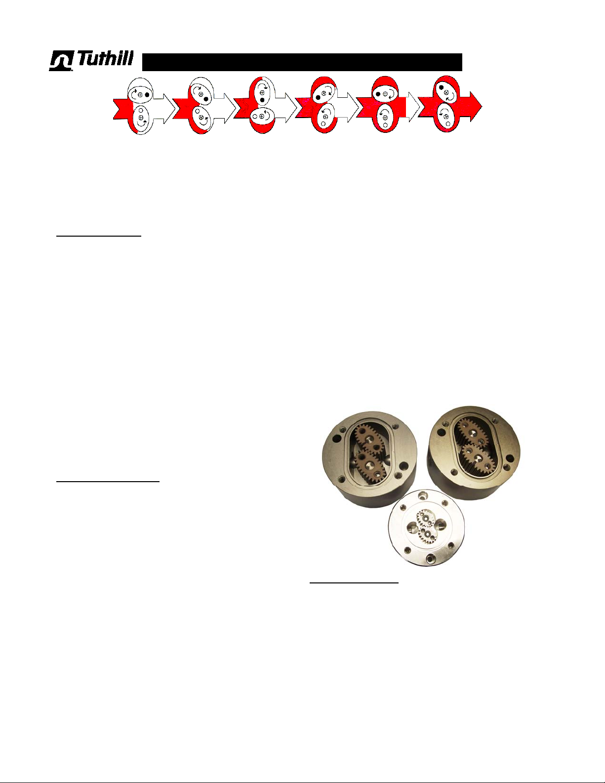
Only 2 moving parts.
Patented ‘Waveform’ oval gears = sustained accuracy with a minimum of maintenance.
No metal-to-metal contact in measuring chamber or in bearings.
The lowest differential pressure values amongst rotary PD meters.
=> Lower Cost of Ownership!
About FPP Meters
We thank you for purchasing an FPP METERS product for
liquid measurement service. FPP
Power Products, is now a trade name of Tuthill Transfer
Systems. FPP was established in 1980. Since its inception,
the company has been dedicated to manufacturing costeffective, high performance flow metering devices for petroleum, industrial, commercial and municipal service.
Our facilities include computerized order entry and inventory
control, so that you are assured of accurate and prompt deliveries. Furthermore, our production personnel ensure that
each order, regardless of size, receives individual attention.
Constant attention to new product development and production design, our high standards of manufacture and final
testing are the reasons why FPP
demanding requirements. With the ‘Waveform’ oval gear
(2003 patent) meter accuracy is better than ever before.
Our meters are used in batching, blending, process control
and to dispense fluids in liquid handling facilities throughout
the World. Service includes gasohol blends, bio-diesel and
special formulation racing fuels.
METERS, formerly Fluid
METERS meet your most
Principle of Operation
Positive Displacement meters have a measuring chamber,
where inlet & outlet are separated by rotors, a rotating element or sliding vanes. As the liquid passes through the flow
meter, it causes the rotors/element/vanes to turn, which
forms the basis for volumetric measurement.
The Oval Gear metering principle is based on two elliptical
(oval) gears, which turn on center on two horizontal shafts
inside a measuring chamber formed by two overlapping cylinders. The oval gears have meshing teeth along their entire circumference, ensuring that the gears will maintain correct position in relation to each other at all times, without the
use of timing gears.
The volume being transferred from the inlet to the outlet side
(= volume measured), forms between the oval gear and the
side of the measuring chamber, alternately in the upper and
the lower half of the measuring chamber. In a full 360° rotation of the gears, four such known volumes are released to
the downstream side of the flow meter.
The flow meter is 100% gland-less with static O-ring seals
only. Internal magnets are detected by a sensor (pulser)
mounted in flow meter case. The pulser generates an electrical on/off signal, which can be used to drive a signal conditioner or an electronic register.
With precision machining and close internal tolerances, the
slippage is minimal for superior linearity (accuracy) over a
broad turn-down ratio. Oval gear meters are largely unaffected by changes in liquid viscosity. In TM Series meters
we expect a shift of no more than 2-4% due to variations in
liquid viscosity between 1 and 100 cSt. As the viscosity
increases further, there is no noticeable change.
To ensure optimum linearity (accuracy), TM Series meters
should be field calibrated correct for individual meter variations, liquid viscosity and local system/operational factors.
TM04A
TM04A
with RS pulser
= 1 magnet in 1 gear
= 2 magnets in 1 gear
with HE pulser
= 4 magnets in gears
TM02D
with HE pulser
Fluid Compatibility
FPP Meter flow meters are available in anodized aluminum
and stainless steel, with a variety of rotor types and seals, to
ensure compatibility with a broad range of liquids. If in doubt
about compatibility with a a specific fluid, please refer to
FPP Technical Manual. If that publication does not provide
a clear answer, please consult with your authorized FPP
Meter distributor, or Customer Care at the factory.
While most refined petroleum products can be handled with
the same flow meter, some require different rotors and/or
seals. Do not change service liquid, without consulting with
your authorized FPP Meter distributor.
1 . 3
Page 4
TM Series, Specifications & Capacity
Materials:
TM●●A Case & cover : Anodized aluminum
Posts (shafts) : 316SS
Seal : Viton™ std., Teflon™ optional
TM●●C Case & cover* : 303SS
Posts (shafts) : 316SS
Seal : Teflon™ standard
TM●●D Case & cover* : 316SS
Posts (shafts) : 316SS
Seal : Teflon™ standard
Rotors (oval gears) : TM02 SS/Teflon bearings
TM03 PPS standard,
SS/Teflon bearings opt.
TM04 PPS standard
TM06 PPS standard
* Pulser retainer (exterior non-wetted fitting) is anodized aluminum.
Pressure Rating:
TM Series meters are manufactured with 2 different pressure ratings (though not in all sizes/materials). Pressure
rating is identified in position 11 in the Part Number:
Pos. 11 in P/No. K L F obsolete 2009
1500 PSI 2500 PSI 400 PSI
MODEL 103 BAR 173 BAR 28 BAR
TM02D
TM03A
TM03D
TM04A
TM04C
TM04D
TM06A
TM06C
TM06D
Pressure rating applies to -40ºF/+100ºF (-40ºC/+38ºC) tem-
perature range. At higher operating temperatures the pres-
sure rating is reduced by factors shown below:
Temperature Rating:
-40°F/+100°F 150°F 200°F 225°F 250°F 275°F 300°F
-40°C/+100°C 66°C 93°C 107°C 121°C 135°C 150°C
A.A.
S.S.
TM Series meters are rated for use on liquids with temperature in -40ºF/+300ºF (-40ºC/+150ºC) range. This temperature rating applies to the flow meter only.
Electronic signal conditioner, totalizer or register attached to
the flow meter will have a different rating, which may differ at
both the low and high end of the range (refer to manual for
electronic components). When that is the case, the electronic component must be installed remote from the flow
meter.
1.00 0.89 0.79 0.75 0.72 0.62 0.43
1.00 0.91 0.83 0.79 0.74 0.70 0.67
Flow Meter Nominal Capacity:
TM02D 0.3 GPM 1.1 lpm
TM03 3.0
TM04 10
TM06 20
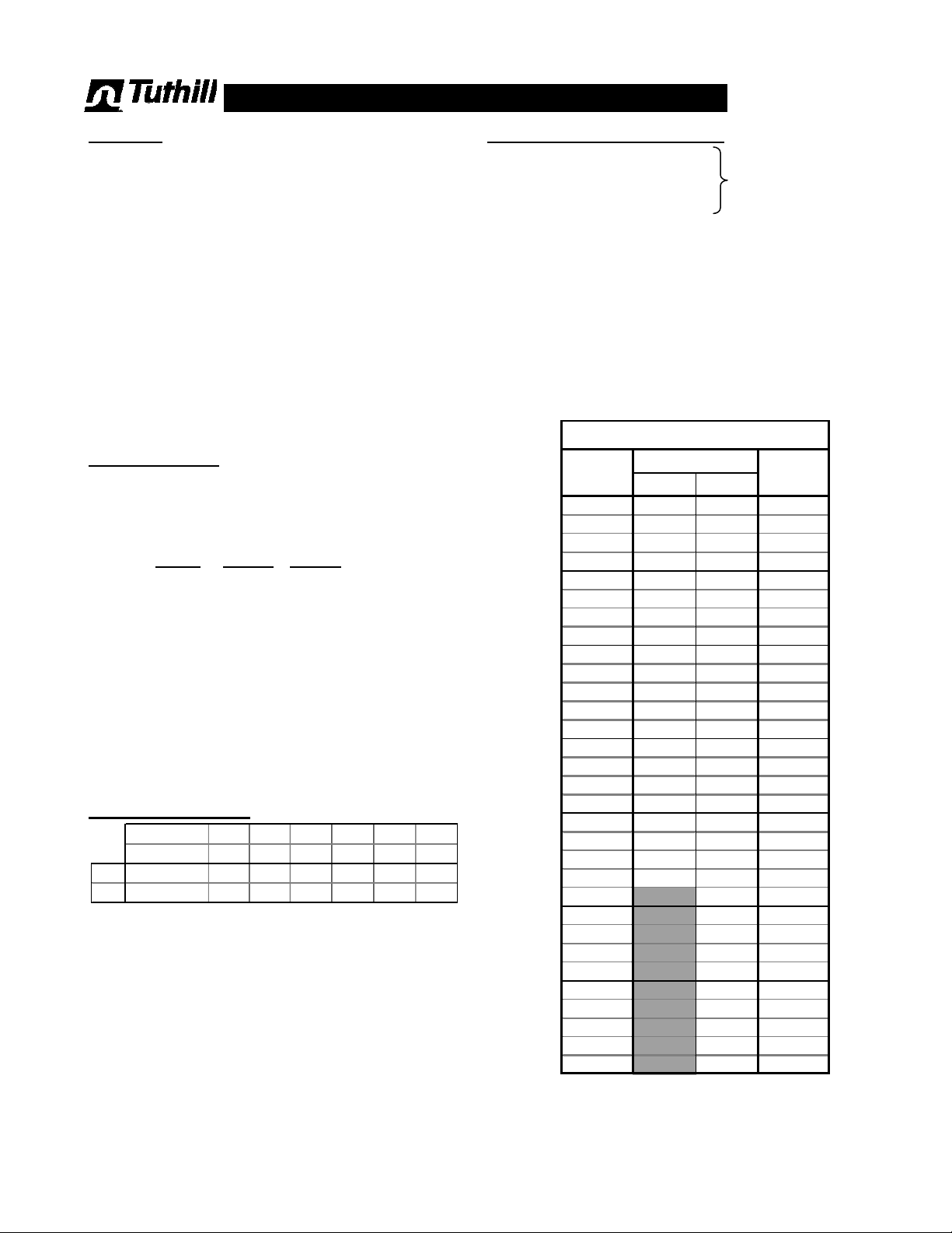
Actual capacity depends upon liquid lubricity, viscosity and
operating temperature. Normal turn-down is 10:1 from nominal (maximum) value shown. Optimum performance is between 50% and 85% of nominal capacity.
When the viscosity exceeds 200 cSt, maximum flow rate is
restricted, but the flow meter will have satisfactory linearity
(accuracy) down to 2-3% of nominal capacity.
To determine model maximum capacity on higher viscosity
liquids, find the flow meter coefficient for maximum liquid
viscosity in table below, and multiply nominal capacity with
this factor.
GPM 11 lpm
GPM 38 lpm
GPM 76 lpm
Flow Meter Coefficient
Liquid
Viscosity
1
10 1.000 1.000 60
50 1.000 1.000 240
100 1.000 1.000 475
200 1.000 1.000 925
300 0.855 0.855 1,425
400 0.770 0.770 1,875
500 0.710 0.710 2,350
600 0.660 0.660 2,825
700 0.625 0.625 3,300
800 0.595 0.595 3,775
900 0.560 0.560 4,250
1,000 0.540 0.540 4,725
2,000 0.350 0.350 9,450
3,000 0.275 0.275
4,000 0.240 0.240
5,000 0.190 0.190
6,000 0.160 0.160
7,000 0.135 0.135
8,000 0.115 0.115
9,000 0.100 0.100
10,000
20,000
30,000
40,000
50,000
60,000
70,000
80,000
100,000
Rotor Code
AE & K
1.000 1.000 32
cSt
On liquids with
1 cSt viscosity.
Viscosity
14,150
18,875
23,600
28,325
33,050
37,750
42,475
0.085
0.072
0.061
0.052
0.044
0.037
0.031
0.026
0.022
0.019
47,200
94,400
141,600
188,800
236,000
283,200
330,400
377,600
424,80090,000
472,000
Liquid
SSU
1 . 4
Page 5
TM Series, Start-Up & Operation
SAFETY INSTRUCTIONS
Make sure that all necessary safety precautions have been
taken, including proper clothing, personal safety equipment
and fire safety equipment if required.
Before Start-Up of the Flow Meter, make certain that:
1. The meter is properly mounted, secured and piped.
2. All connections are tight.
3. All bleed and drain valves are closed.
4. Do NOT smoke near meter, or use meter near an open
flame, when metering flammable liquids. Fire or Explosion could result.
5. This meter is not intended for use on liquids, which require 3A Sanitary equipment for human consumption. It
may be used on edible liquids, which do not spoil easily,
such as vegetable oils, liquid sweeteners & similar.
Install the Flow Meter and Accessories in compli-
ance with all applicable Local, State & Federal
Construction, Electrical and Safety Codes.
Installation
Positive Displacement meters are designed to operate full
of liquid. The meter should be installed in a manner, so
that it remains full of liquid at all times.
The flow meter is not designed to operate on air, but the
design and materials of construction allow for operation
on vapor for short periods of time without damage to the
oval gears or flow meter internals.
Hydraulic shock can be harmful to flow meter and other
system components. Consideration to eliminate hydraulic
shock should be given in selection of pump and design of
the piping system.
The flow meter can operate with liquid going Left-to-Right,
Right-to-Left or Vertical Up, but it must be installed with
rotor shafts in horizontal position (= with vertical end
covers). Failure to observe this will impact negatively on
flow meter accuracy.
Protective caps installed in flow meter flanges prior to
shipment should remain in place until you are ready to
install in the piping system.
It is recommended that a Strainer be installed upstream
of each flow meter, to prevent damage from foreign matter, such as welding slag, pipe scale or parts breaking off
other equipment.
Allow adequate space for removal of strainer basket
cover, so strainer basket can be cleaned.
OPERATING TEMPERATURE
TM Series meters are rated for operation from
-40°F/+300°F (-40°C/+150°C). However:
They are not suitable for cryogenic service.
When temperature exceeds +120°F (+50°C), ‘K’ ro-
tors must be used, and pressure rating is reduced.
Refer to FPP Technical Manual for details.
OPERATING PRESSURE
TM Series meters Maximum non-shock Operating
Pressure is (see position 11 in the P/No.):
Code F 400 PSI (= 10.3 BAR) at 100°F
Code K 1500 PSI (= 103 BAR) (+38°C).
Code L 2500 PSI (= 175 BAR)
The flow meter should never be operated in excess of
this pressure. Care should be taken to eliminate thermal and hydraulic shock conditions, so that system
pressure never exceeds the flow meter’s Maximum
Working Pressure rating.
Flush the system to remove all debris, scale and welding
slag prior to flow meter installation. If this is not possi-
ble, temporarily remove rotors (oval gears), and reinstall
after the system has been flushed.
Apply pipe compound to male threads. Do NOT use Tef-
lon tape.
Avoid pipe stress when installing the flow meter.
When installing the flow meter, consider future mainte-
nance of both flow meter and accessories. The meter
can be serviced in place, provided block (isolation) valves
are included, and adequate space allowed.
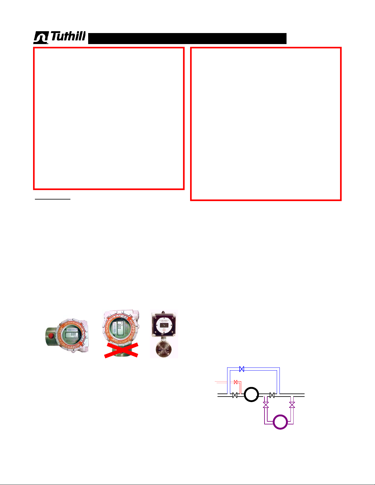
In critical installations a by-pass line is recommended,
so flow can continue while flow meter is being serviced.
Thermal relief valves are recommended, and should be
installed whenever it is possible to block (isolate) the flow
meter between two valves. The pressure rise in a closed
system, from just a few degrees increase in temperature,
can be many times normal working pressure.
Connections for calibration should be provided during
installation. An easy means for diverting flow into a calibration vessel (or through a Master Meter) should be considered.
THERMAL
1 . 5
RELIEF
BYPASS
OPERATING
METER
TEMPORARY MASTER METER
Page 6

Y
Start-Up, Operation & Calibration
Start-Up & Operation
Very slowly fill the system with liquid, to avoid operating the
flow meter on air or vapor. This can be accomplished in the
following manner:
1. Throttle the meter inlet valve, and allow the system to fill
slowly by gravity.
2. Crack open the outlet valve. Start the pump, and then
slowly crack open the inlet valve, filling the meter slowly
before fully opening the inlet and outlet valves.
In normal operations:
Avoid sudden changes in temperature.
Avoid sudden changes in flow rate.
Gradually increase or decrease the flow rate.
Flow Meter Calibration
It is recommended that written records be maintained on all
flow meters. These records should include:
Supplier and Service Department phone number.
Date of installation.
Details of maintenance performed.
Flow meter initial K Factor (number of pulses per unit of
volume).
Date & result of each re-calibration, with changes in flow
meter K Factor.
TM Series flow meters are given a functional ’Pass or Fail’
test prior to shipment, but written records of this test are not
maintained. The nominal K Factor shown on flow meter
cover is an average value, which should be used as a starting point when field calibrating on actual liquid of operation.
Nominal K Factor on 1 cP liquid
These values are subject to individual flow meter variation,
as well as expected fluctuation due to liquid viscosity (see
above).
HE pulser RS pulser
TM02 7700 PPG 2035 ppl 3750 PPG 1017 ppl
TM03 2800 PPG 740 ppl 700 PPG 185 ppl
TM04
TM06
805 PPG 213 ppl 201 PPG 53 ppl
405 PPG 107 ppl 101 PPG 27 ppl
Frequency
TM Series meters are not intended for use in Custody
Transfer service, so Weights&Measures regulations should
not apply. If local authorities issue regulations for non-W&M
flow meters, such regulations must be observed.
If user is ISO9000 certified, user ISO standards will indicate
frequency of re-calibration for instrumentation. Those rules
should be observed. If no regulations or standards apply,
our recommendations are:
A. Calibrate immediately after installation.
B. Re-calibrate after 15-30 days.
C. Re-calibrate after 180 days and again after 360 days.
After the run-in calibration (B) and follow-up calibrations (C),
it is possible to evaluate degree of change under normal
operating conditions. Based on values found, and total volume being metered under normal operating conditions, decide whether a 6, 12 or possibly 24 month schedule should
be adopted.
Procedures & Methods
Flow meters used in systems where the flow rate can fluctuate, should be tested at minimum, intermediate & maximum
flow rates. In non-W&M service, a flow meter always operating at a steady flow rate, can be tested at that flow only.
All tests should be repeated 3 times to confirm repeatability.
All tests should be of at least 60 second duration, to minimize effect of flow meter error during start-up & shut-down.
After calibrating a known volume (X) into an accurate
prover, or through a master meter, compare with register
reading (Y) and calculate correction:
X-
X
x 100
= % correction
When re-calibration has established that a correction is
required, change flow meter K Factor:
When prover/master meter reading is less than flow
meter register reading, add percentage calculated to
the original K Factor..
When prover/master meter reading is more than flow
meter register reading, subtract percentage calculat-
ed from the original K Factor.
Accuracy curves of individual flow meters vary some. Also,
the accuracy curve of all flow meters will shift due to variations in liquid viscosity; perhaps as much as 3-4% from 1 cSt
to 100 cSt. The accuracy curve will not shift significantly at
higher viscosities, even if the actual operating liquid has
viscosities up to 500,000 cSt.
Since we cannot test on actual fluid of operation, it is
the responsibility of the buyer to field calibrate in place
of service on actual operating liquid.
Circulate product through the flow meter for a few
minutes. Then perform at least 3 more tests, to confirm
flow meter accuracy & repeatability.
If the flow meter does not repeat, it will likely require a
new set of rotors (oval gears).
Before ordering new gears, inspect the measuring
chamber for scratches or wear. If the measuring
chamber is scratched or scored beyond what can be
smoothed with emery paper, the flow meter should be
replaced.
Finally, enter date and % correction on the permanent
flow meter record.
1 . 6
Page 7

Trouble Shooting & Service
Prior to opening or disassembly of any flow meter, all internal pressure mu st be relieved and all liquid must be
drained. This must be done in accordance with applicable company and local codes & ordinances.
Make sure that all necessary safety precautions h ave been taken, including proper clo thing, personal safety equipment and fire safety equipment if required.
No Flow
Blocked strainer basket. Clean the basket.
Faulty or non-functioning pump. Repair pump.
Valve stuck in closed position. Check and repair valves.
Flow meter ‘frozen’ due to build-up of chemical salts (or
frozen water) inside the measuring chamber. Clean the
flow meter (see page 1.8), and inspect for damage.
Meter jammed on a particle that has passed through a
damaged strainer basket. Remove particle and replace
rotors if necessary, replace strainer basket.
Reduced Flow Rate
Strainer basket partially blocked. Clean the basket.
Pump not functioning correctly. Repair pump.
Valve stuck in partially closed position. Check valves and
repair.
Meter rotors (oval gears) partially ‘salted’ with chemical
deposits, slowing the movement. Clean the meter (see
page).
Product Flows, but the register does not record
Check power supply to the register.
Check the connection between the pulser and the elec-
tronic register.
Check pulser output (see page 1.8). Replace if needed.
If product is flowing, and the flow meter is generating a
pulse signal, the problem is in the electronic register.
Please refer to the manual for the electronic register.
Product Flows, register does not record correctly
If error factor is constant, the flow meter is fine. The likely
cause is either:
Incorrect K Factor in the electronic register. Re-
calibrate the meter and correct the K Factor.
A constant problem with air getting into the system.
Review system design and control valves.
If the error is random, the likely cause is either:
Poor cable connections (insulation not trimmed, or
stray strands getting close to incorrect contacts). This
can be signal conditioner (if included) or where pulse
signal is connected to the register. Inspect and correct
connections as necessary.
Valve leaking, allowing a portion of the system to drain.
Check & repair valves.
An intermittent problem with air in the system, com-
bined with inadequate air elimination. Review system
design and control valves.
Interference from other electrical equipment nearby.,
possibly combined with sub-standard cables.
Breaking Teeth on Rotors (Oval Gears)
This is a sign of hydraulic shock conditions in the system.
Common sources:
Starting or stopping flow too rapidly. Replace dam-
aged components and correct operational practices.
Pump by-pass not adjusted properly. Re-adjust as
necessary.
Leakage from Cover
The seals (and possibly end covers) have been damaged
due to excessive pressure. There are two possible sources:
Starting or stopping flow too rapidly. Replace dam-
aged components and correct operational practices.
The flow meter is in a system, where it can be isolated
between two valves. Add a Thermal Relief Valve to
bleed off excess pressure when the temperature rises.
Installation, Maintenance & Service must be performed
by personnel:
A. Qualified to work on this type of equipment.
B. Familiar with all applicable local codes and ordi-
nances covering the type of service, where the flow
meter is used (gasoline, LPG, etc.).
Avoid pipe strain and stress when making flow meter repairs. The weight of the pipe and the flow meter must be
supported independently. This allows the flow meter to be
serviced without affecting the alignment of piping.
Avoid prying or exerting heavy pressure on precision parts,
as this can affect the performance of the flow meter. Assure
that all machined parts are free of burrs and nicks. Stone all
machined surfaces if necessary to remove burrs.
Always coat bolt threads with an anti-seize or an appropriate
lubricant. This prevents thread damage, and assures that
proper torque values are applied during re-assembly. If
threads are damaged, repair using inserts.
Relieve All Internal Pressure Prior to Opening
Drain Liquid prior to Working on Flow Meter
Rinse with Neutral Liquid
prior to Seasonal Storage
Triple Rinse with Neutral Liquid
prior to Shipment for any reason.
1 . 7
Page 8
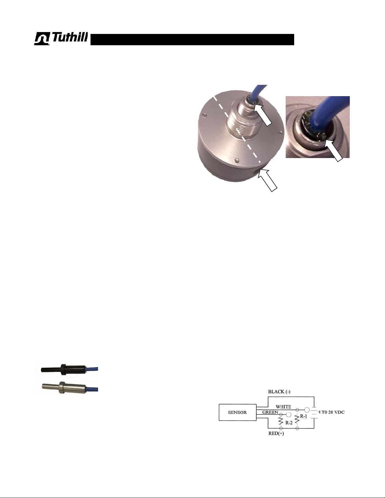
Hall Effect Sensor (Pulser)
Intrinsically Safe rated sensors for
Cl. 1, Div. 1, Grp. D and Zone 0 applications
CD1002, UL 9HA6, DEMKO 04 ATEX0334817 EEx ia IIA T4
The standard sensor (pulser) is a Hall Effect device, which
may have one or two output signals. To retain above ratings,
it must be powered from a secure circuit through an approved
barrier. A PIA-300 signal conditioner may be required, when
connected to non-FPP electronics
Specifications:
Operating speed : 0-100 kHz.
Operating temperature : -40ºF/+300ºF (-40ºC to +150ºC)
Supply voltage : 4-28 VDC
Supply current : 13.5 mA max.
Output type : SINK (add PIA-300 for source)
Output voltage @ 20 mA: 0.40 V max
Output sink current : 20 mA max
Leakage current : 10 μA max
Magnetics type : Bipolar, operated with alternat
ing north & south magnetic
poles.
Internal pull-up resistor : 10KΏ
Transmission distance : Max. 100’ (30 m) without PIA-300
Pull-up Resistor (R1 & R2)
The sensor has one internal 10KΏ pull-up resistor for each
output signal. If used directly with non-FPP electronics, verify
whether this is adequate for solid communications.
Cable
24 AWG, foil shield & drain wire, blue PVC jacket, RoHS.
75VDC. Capacitance: 185 nF/km. Inductance: 0.65 mH/km.
Standard with 18” (45 cm) leads. 120” (305 cm) or
480” (1220 cm) leads optional.
Color Code:
Red Positive, 4-28VDC
Black Negative (signal common)
White Signal output A
Green Signal output B (optional)
3 conductor: Standard Hall Effect sensor
4 conductor: Dual signal Hall Effect sensor (Quadrature)
2 conductor: Optional Reed Switch sensor (see page 1.9).
A PIA-300 amplifier is required for cable lengths exceeding
100’ (30 m).
Easy Identification of replacement sensors
Black anodized housing is for
TM04 & TM06 models.
Metallic finish is for use in
TM02 & TM03 models
Installation
Do NOT remove the sensor (pulser) from the flow meter,
unless trouble shooting has indicated a problem in the sen-
sor. To remove the sensor, loosen the lock nut on the sensor retainer (sensor well in model TM06). The sensor can
now be pulled out.
CAUTION
If the sensor is
connected incorrectly,
it will be damaged
beyond repair.
1 . 8
To install a new sensor, look at the top of the replacement
sensor. An internal PC board is visible through the epoxy
(usually protrudes slightly from the epoxy). This PC board
must be aligned parallel with a line drawn between flow
meter inlet and outlet.
Close-Up
P
C
b
o
a
r
d
P
C
b
o
a
r
d
I
N
L
E
T
Trouble Shooting the Sensor
There are three components to be examined to determine
why there is no pulse count coming from the flow meter:
1. Flow meter with magnets in the oval gears.
Verify that liquid is flowing.
Verify that sensor (pulser) cable is intact.
2. The sensor (pulser)
Remove the sensor from the flow meter. Expose
the black & white leads (in dual signal sensors, also
the green lead). This can be done at a convenient
junction, or at the register.
Use an volt meter to measure the voltage between
the white & black leads. It should be nearly equal to
the power supply voltage provided on the red lead.
Pass a magnet across the tip of the sensor. The
voltage must switch to nearly zero (less than 0.2 V).
If the magnet does not actuate the sensor, the sensor has failed.
For two channel sensors, repeat this test across
black & green leads.
3. The counter (or receiving instrument)
If liquid is flowing, and the sensor reacts to a mag-
net, the problem is in the counter/receiving instrument (or possibly in a signal conditioner installed
between the sensor & counter/receiving instrument.
Please refer to the manual for the this device.
See Control Drawing on page 1.10
Page 9
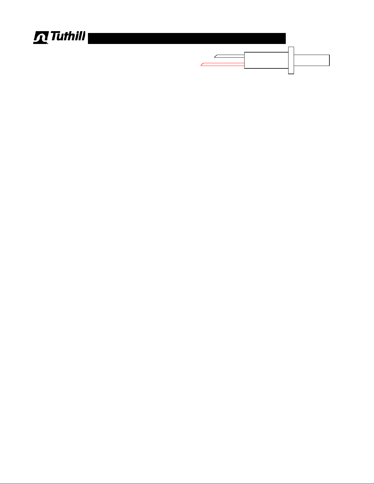
Optional Sensors (pulsers)
Reed Switch
This sensor is strictly for use with battery powered stand
-alone registers, where no external power source is avai l-
able. If external power is available, Hall Effect pulser
should be used - even when the register is battery powered.
In so called ‘pulse meter’ service, either Hall Effect or
Quadrature Hall Effect pulser must be used - depending
upon the requirements of the receiving instrument.
The Reed Switch sensor (pulser) consists of a set of contacts, hermetically sealed in a glass tube, protecting the contacts from dirt and corrosion of the the outside world. Contacts are actuated by an external magnetic field, provided by
permanent magnets inside the rotors.
This is a mechanical device with a finite life. To extend pulser
life, flow meters with Reed Switch pulser are only available in
‘low resolution’ version.
When the pulser starts to wear out, it rarely fails instantly.
Instead it starts to miss pulses. We recommend that the flow
meter be recalibrated on a regular basis. Once pulser failure
is detected, establish a schedule for pulser replacement as a
matter of normal maintenance.
Contact Rating:
Volts DC max. : 30 VDC
Amps DC max. : 0.01 A
Watts DC max. : 0.25 W
Initial resistance : 1.0 Ώ
Operating Temp range : -40ºF/+300ºF (-40ºC/+150ºC)
D-Must operate : 0.125” (3.2 mm)
D-Must release : 0.400” (10.2 mm)
Cable specifications:
24 AWG, foil shield & drain wire, blue PVC jacket, RoHS.
75VDC. Capacitance: 185 nF/km. Inductance: 0.65 mH/
km.
Standard with 18” (45 cm) leads. 120” (305 cm) optional.
When powered through an approved barrier, Reed Switch
sensors are Intrinsically Safe.
BLACK
RED
Trouble Shooting the Sensor
CAUTION: Do NOT use an Ohm-meter to test
the reed switch sensor (pulser).
Remove the sensor from the flow meter, and expose the
red & black leads. This can be done at a convenient junction, or at the register.
Measure the voltage between the red & black leads. It
should be equal to the voltage provided by the register.
Pass a magnet across the tip of the sensor, the voltage
should switch to zero (less than 0.2 V).
If the magnet cannot activate switching of the sensor, then
the sensor has failed and must be replaced. There are no
alignment requirements for the Reed Switch sensor.
1 . 9
Page 10
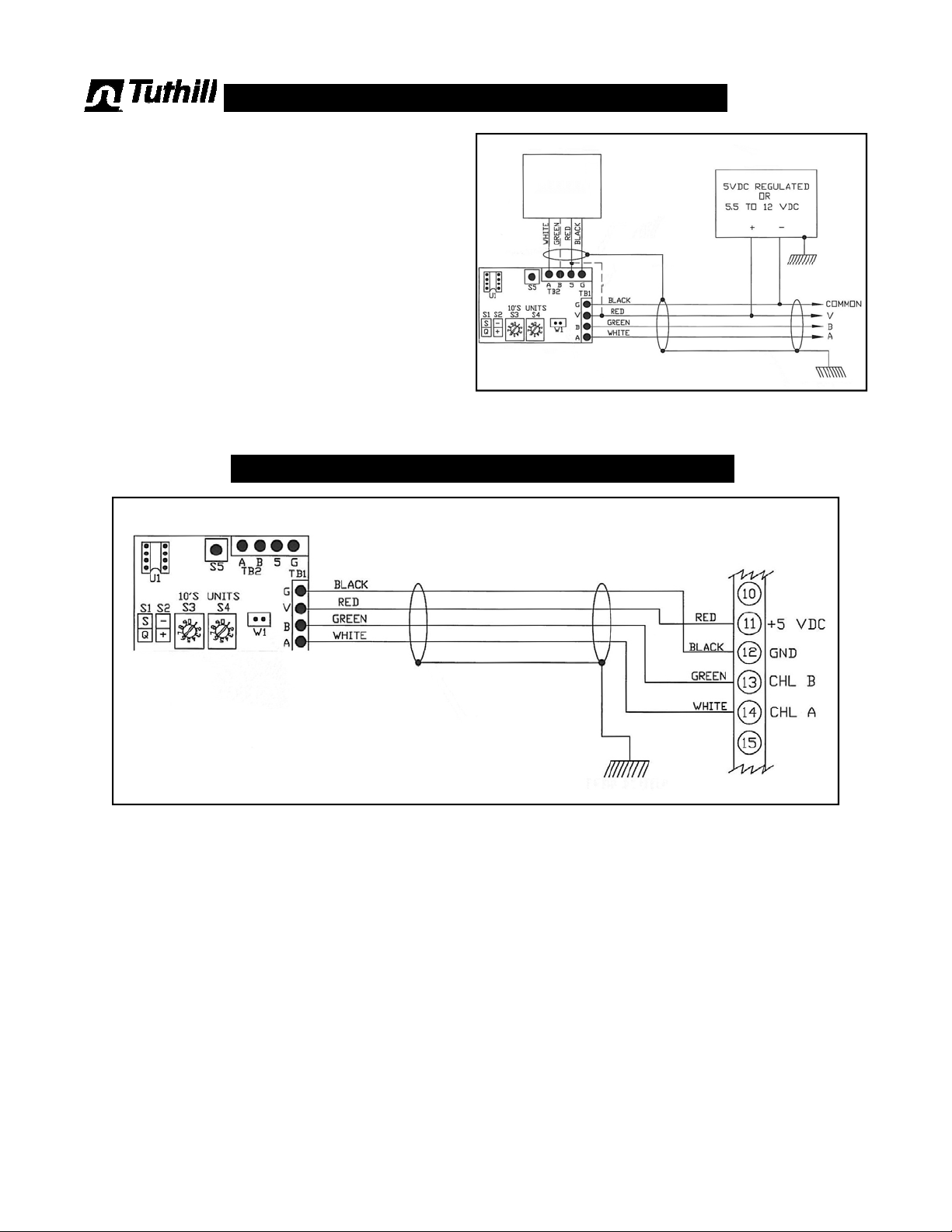
Optional Quadrature Signal
When a TM Series flow meter is to be used with an electronic
register requiring dual channel signal (Quadrature signal), the
SCL signal conditioner is used. This produces a simulated
Quadrature signal for the register, which will record volume
correctly, but it does not permit detection of reverse flow.
The SCL is voltage specific. The standard version can be
field selected for 5VDC regulated, or 6-12VDC non-regulated.
An optional version is available for 24VDC service.
The SCL can be mounted:
In a separate enclosure inside the case of the primary
register (such as the EMR
3
electronic register).
In a NEMA 4X enclosure, either mounted on the flow
meter, or installed remote.
In a NEMA 7/4X enclosure, either mounted on the flow
meter, or installed remote.
SCL wired to EMR3 register
1 . 10
Page 11
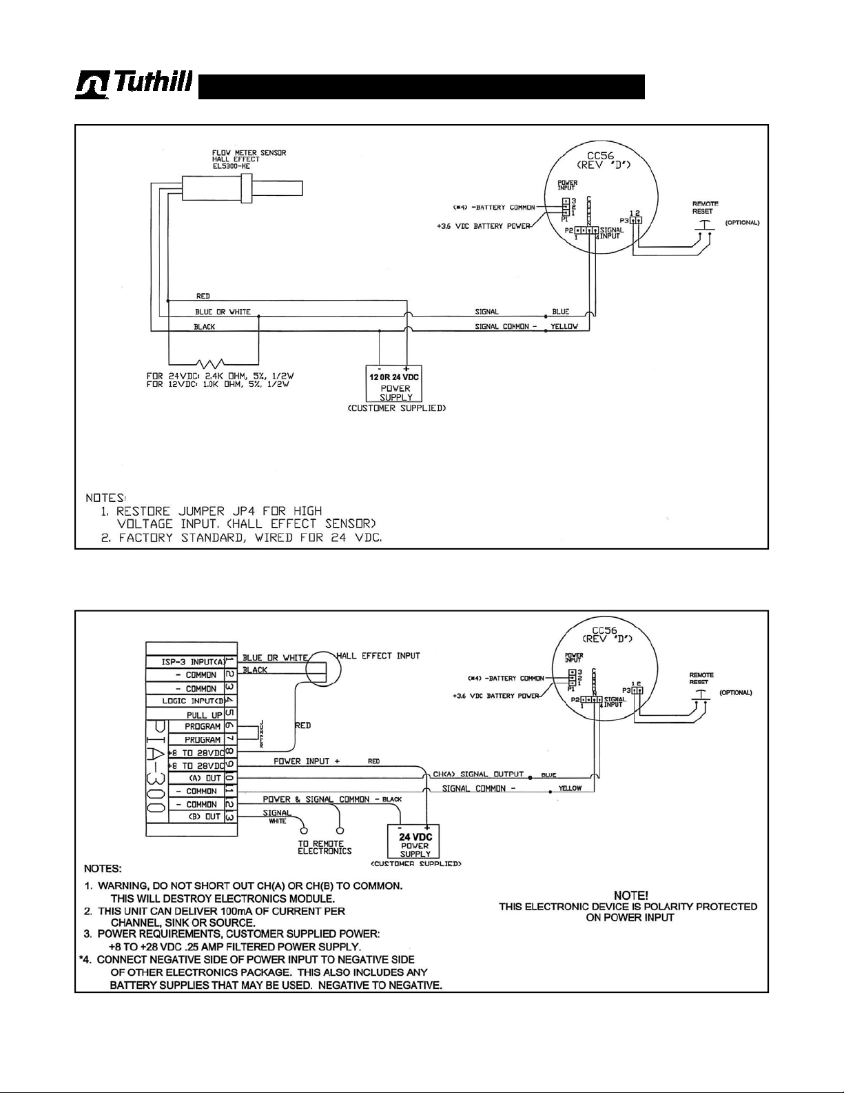
Wiring Diagrams
HE pulser (DC powered) to CC56 register (battery powered)
HE pulser (DC powered) to PIA-300 with
Channel A to CC56 register, Channel B = pulse output to ??
1 . 11
Page 12
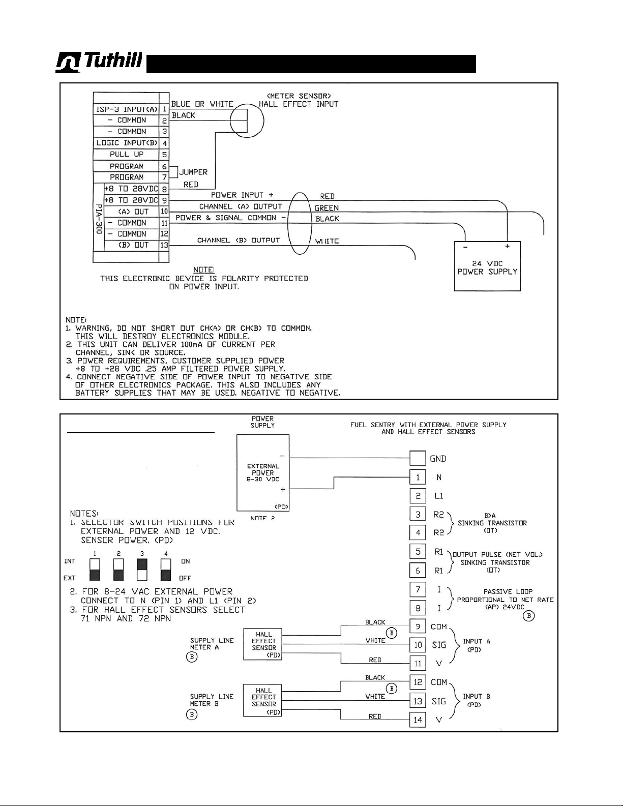
Wiring Diagrams
PIA-300 pulse Isolator/Amplifier/Splitter
HE pulser (DC powered) to
HE pulser in ‘Fuel Sentry’
1 . 12
Page 13
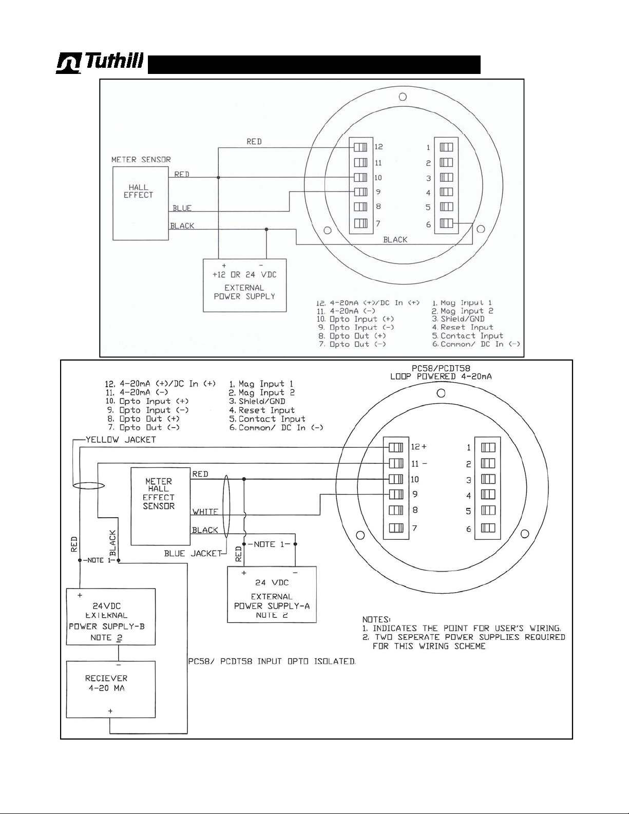
Wiring Diagrams
HE pulser to PC58 or PCDT58
HE pulser to PC58 or PCDT58 with 4-20 mA Analog signal
1 . 13
Page 14
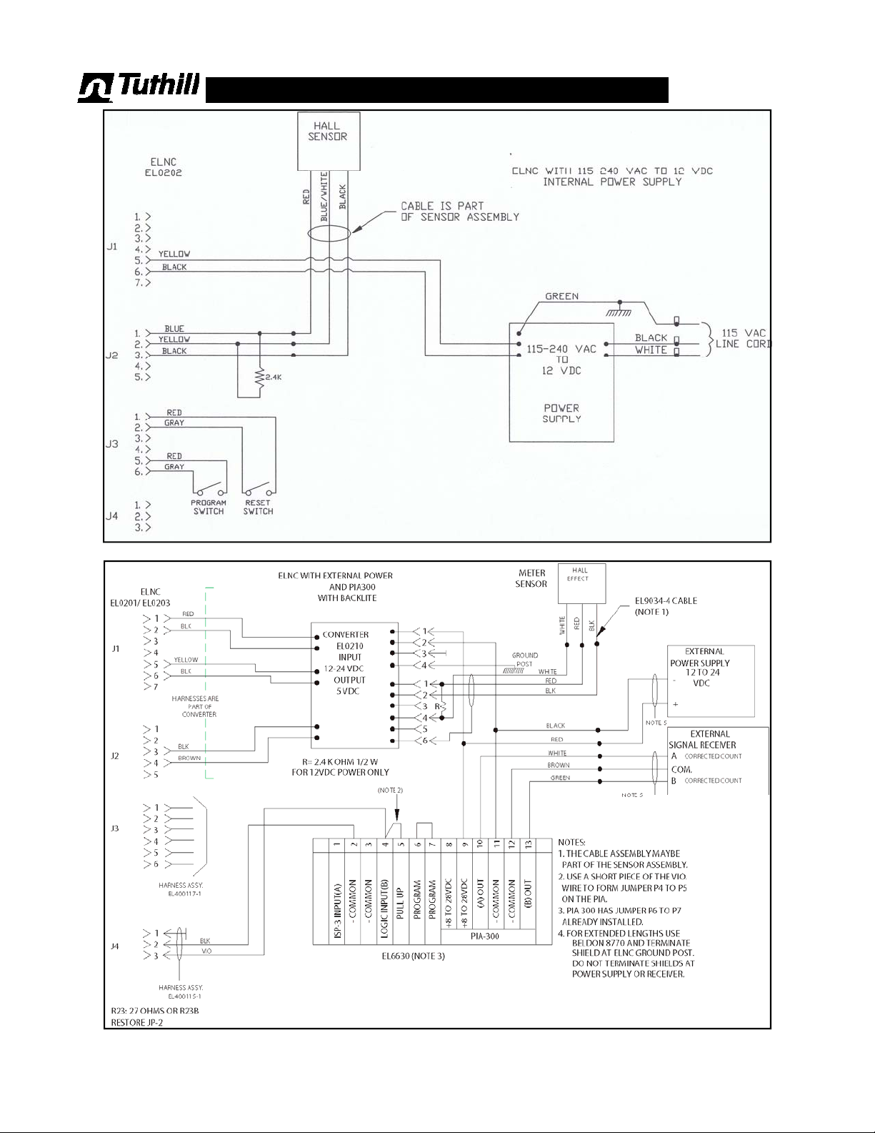
HE pulser to ELNC
Wiring Diagrams
HE pulser to ELNC with Backlight & 10:1 pulse out
1 . 14
Page 15
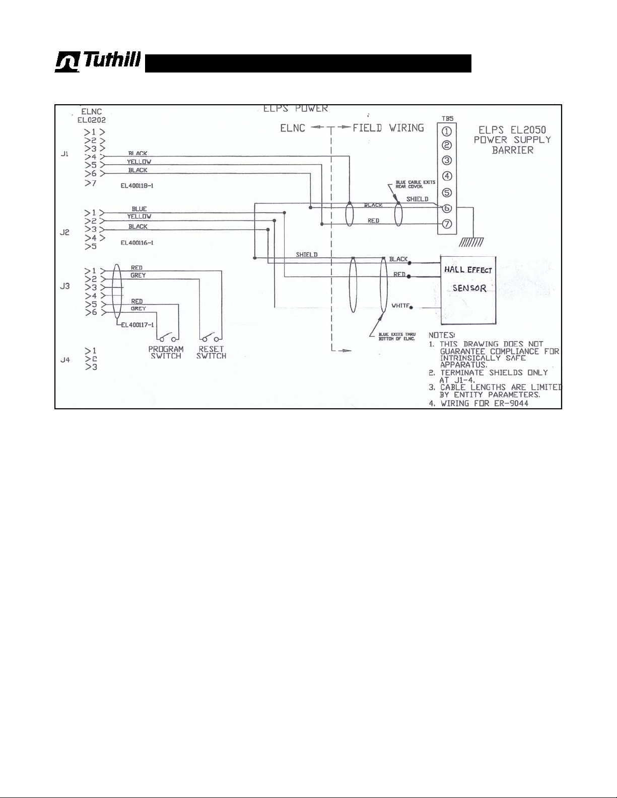
Wiring Diagrams
HE pulser with EL2057 & ELNC for use in Hazardous Zone
1 . 15
Page 16
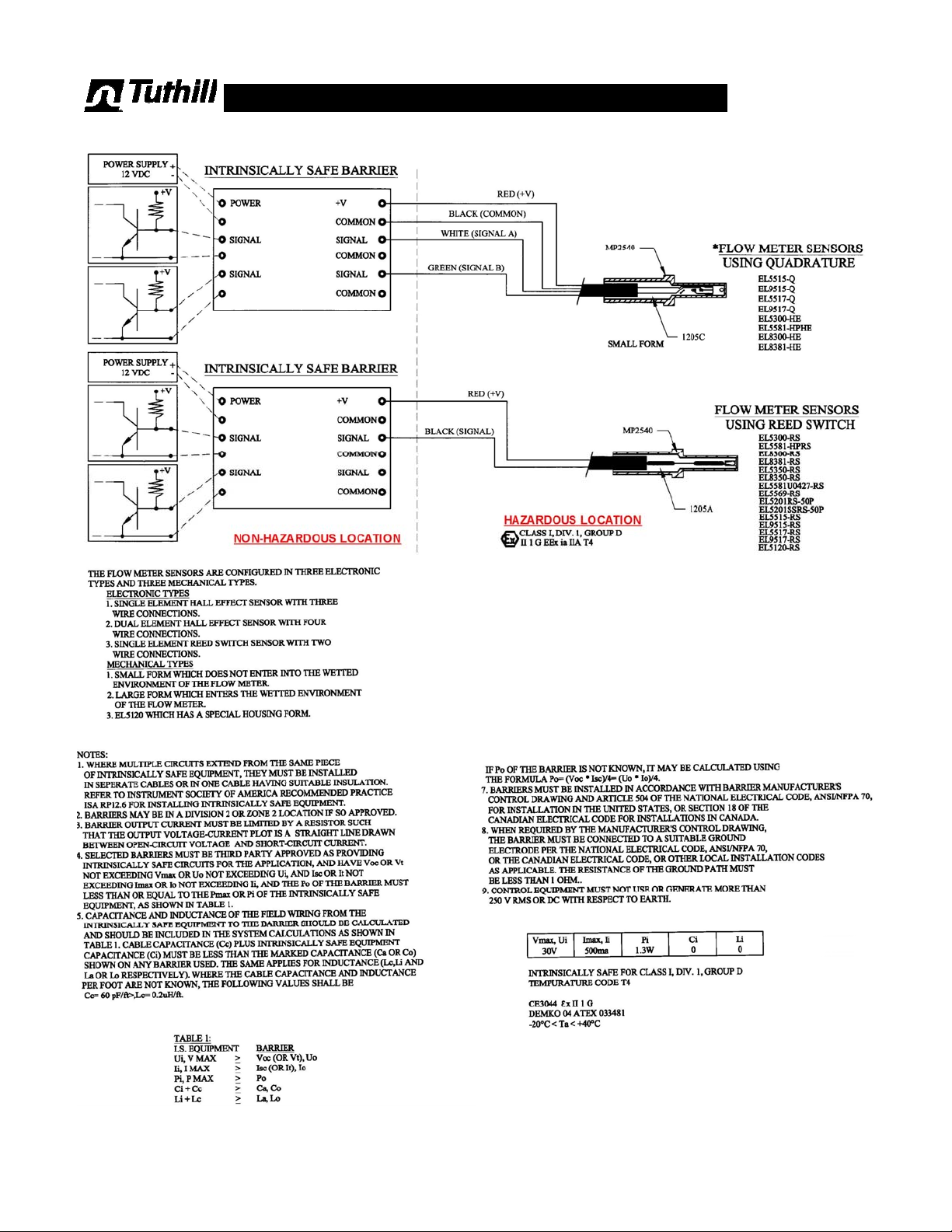
Control Drawing
1 . 16
Page 17
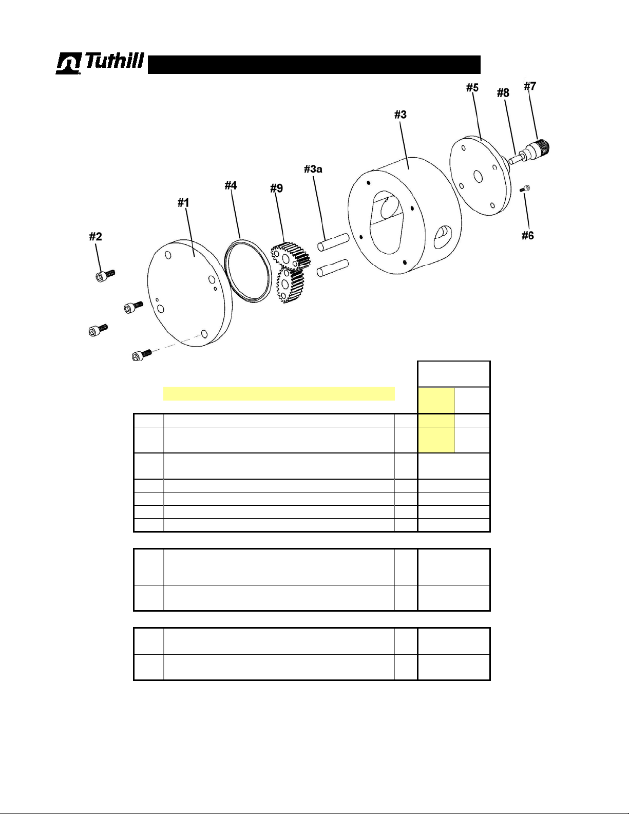
TM02D Parts List
TM02D
Stainless Steel
:
2009
400 PSI ( 28 BAR) version b eing phased out
REF Description QTY 28 BAR 103 BAR
1.
Meter c over plate 1 CP86502 CP8625
2.
Screw , cov er plate (10-32 X 3/8" SHCS 303SS) 4 FS9651
Screw , cov er plate (10-32 X 5/8" ALSTSHCS) FS1660
3.
Meter body w ith posts, 1/4" NPT ports 1
Meter body w ith posts, 1/4" BSP ports
4.
O-ring, cov er plate, Teflon 1
5.
Pulser retainer ('Top Hat') 1
6.
Screw , pulser retainer (8-32 x 1" SHCS SS) 2
7.
Lock nut 1
400 PSI 1500 PSI
MB99011
MB99021
SL2029
MP2084
FS9540
MP2541
Sta ndard pulser/ge ar s et:
Standard Hall Ef fect s ensor (pulser).
8.
When used with non-FPP electronics, a PIA-300 signal
conditioner is often required.
9.
Gear set: SS/Teflon bearings, 2 magnets
Nominal K Factor: 7700 PPG (2035 ppl)
1 EL5300-HE
1 GSTM02-2
Optional pulse r/gea r set:
8.
Optional reed s w itch sensor (pulser),
For use with FPP battery powered electronic register
9.
Gear set: SS/Teflon bearings, 1 magnet
Nominal K Factor: 3850 PPG (1018 ppl)
K Factor (pulse resolution) is nominal
subject to up to 3-4% shift on liquids w ith viscosity > 100 cSt.
. Individual flow meters vary , and are
1 EL5300-RS
1 GSTM02-1
M M 02P 2009-06
2 . 1
Page 18
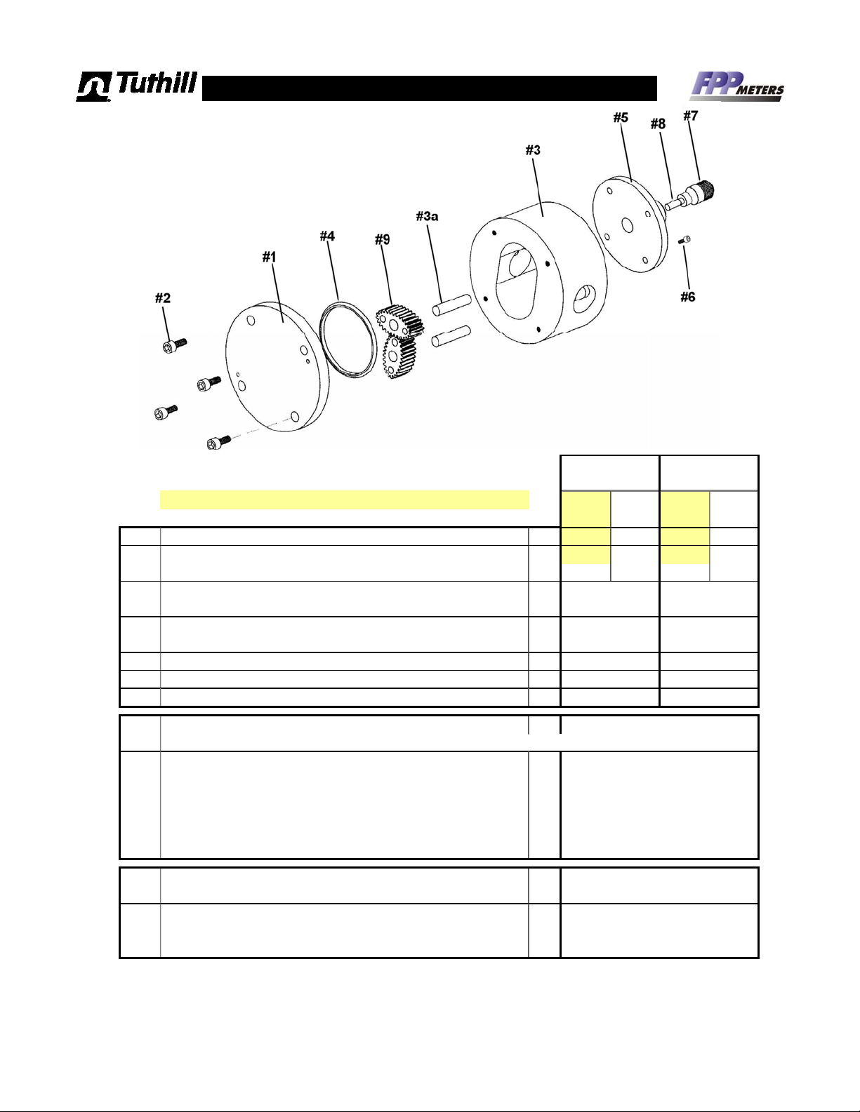
TM03A & TM03D Parts List
A
TM03A TM03D
nod. Aluminum
:
2009
400 PSI (28 BAR) version being phased out
REF Description QTY 28 BAR 103 BAR 28 BAR 103 BAR
1.
Meter c over plate 1 CP2800 CP2850 CP9800 CP9650
2.
Screw , cover plate (10-32 X 3/8" SHCS 303SS) 6 FS9651 FS9651
Screw , cover plate (10-32 X 5/8" ALSTSHCS) FS1660 FS1660
3.
Meter body w ith posts, 3/8" NPT ports 1
Meter body w ith posts, 3/8" BSP ports
4.
O-ring, cover plate, Viton 1
O-ring, cover plate, Teflon
5.
Pulser retainer ('Top Hat') 1
6.
Screw , pulser retainer (6-32 x 1.1/2" SNCS SS) 4
7.
Lock nut 1
400 PSI 1500 PSI 400 PSI 1500 PSI
MB2800-21
MB2801-21
SL1033 (std.)
MP2085
FS9450
MS2541 MS2541
Stainless Steel
MB980021
MB980121
na
SL2033SL2033 (opt.)
MP2085
FS9450
Hall Ef fect s ensor (pulser).
8.
When used with non-FPP electronics, a PIA-300 signal conditioner is often required.
9.
PPS, Low viscosity/temperature Nom. 2800 PPG (740 ppl) 1 GS530R2600 (std. 2009+)
Gear Nom. 1400 PPG (370 ppl) GS530R1300 (std. pre-2009)
Set PPS, High Temperature (or high viscosity) Nom. 2800 PPG (740 ppl) GS530RMV2600 (optional)
Nom. 1400 PPG (370 ppl) GS530RMV1300 (optional)
SS gears w ith Tef lon bearing Nom. 2800 PPG (740 ppl) GSTM03CT-4 (optional)
Low viscos ity/any temperature Nom. 1400 PPG (370 ppl) GSTM03CT-2 (optional)
8.
Reed Sw itch sensor (pulser),
For use with FPP battery powered electronic register
9.
PPS, Low viscosity/temperature Nom. 700 PPG (185 ppl) 1 GS530R650 (optional)
Gear PPS, High Temperature (or high viscosity) Nom. 700 PPG (185 ppl) GS530RMV650 (optional)
Set SS gears w ith Teflon bearing Nom. 700 PPG (185 ppl) GSTM03CT-1 (optional)
K Factor (pulse resolution) is nominal
to 3-4% s hift on liquids w ith viscos ity > 100 cSt.
. Individual f low meters vary, and are subject to up
2 . 2
1 EL5300-HE
1 EL5300-RS (optional)
M M 03P 2009-06
Page 19
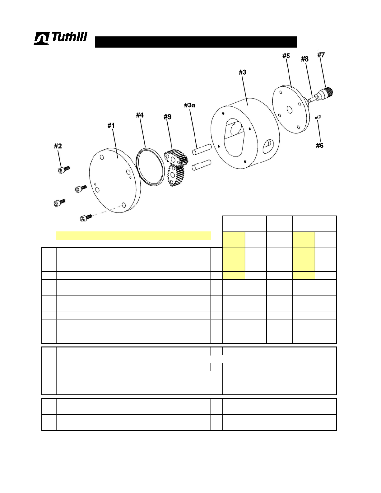
TM04A, TM04C & TM04D Parts List
)
A
TM04A TM04D
nod. Alum inum 316 Stls. Ste e l
:
2009
REF Des cription QTY 28 BAR 103 BAR 173 BAR 28 BAR 103 BAR
1.
Meter c over plate 1 CP2501 CP2506C CP8575 CP9500 CP9501
2.
Screw , cover plate (1/4-20 x 1/2 SHCS, SS) 4 FS9812 FS9812
Screw , cover plate (1/4-20 x 5/8 SHCS) FS1802 FS1802
3.
Meter body w ith posts, 1/2" NPT ports 1 MB8575-1
Meter body w ith posts, 1/2" BSP ports
4.
O-ring, cov er plate, Viton 1
O-ring, cov er plate, Teflon SL2138
5.
Pulser retainer ('Top Hat') 1 MP8550
6.
Screw , pulser retainer (8-32 x 1" SHCS SS) 4 FS1901
7.
Lock nut 1 MP2541
Hall Effect s ensor (pulser).
8.
When used with non-FPP electronics, a PIA-300 signal conditioner is often required.
9.
PPS, Low Viscosity/Temperature Nom. 805 PPG (213 ppl
Gear Nom. 403 PPG (106 ppl) (std. pre-2009)
Set PPS, High Temperature (or high viscosity) Nom. 805 PPG (213 ppl) (optional)
400 PSI (28 BAR) version being phased out
Nom. 403 PPG (106 ppl) (optional)
400 PSI 1500 PSI 2500 PSI 400 PSI 1500 PSI
MB25011
MB25021
SL1138 (std.)
SL2138 (opt.) SL2138
MP2086
FS9812 FS9812
MS2541 MS2541
1 EL5581-HPHE
1 (std. 2009+)
TM04 C
303 SS
FS1901
MB95011
MB95021
na
MP2086
GS540R380
GS540R760
GS540RMV380
GS540RMV760
8.
Reed Sw itch sensor (pulser),
For use with FPP battery powered electronic register
9.
PPS, Low Viscosity/Temperature 1 GS540R190 (optional)
PPS, High Temperature (or high viscosity) GS540RMV190 (optional)
K Factor (pulse resolution) is nominal
to up to 3-4% s hift on liquids w ith viscosity > 100 cSt.
. Individual f low meters var y, and are subject
2 . 3
1 EL5581-HPRS (optional)
M M 04P 2009-06
Page 20
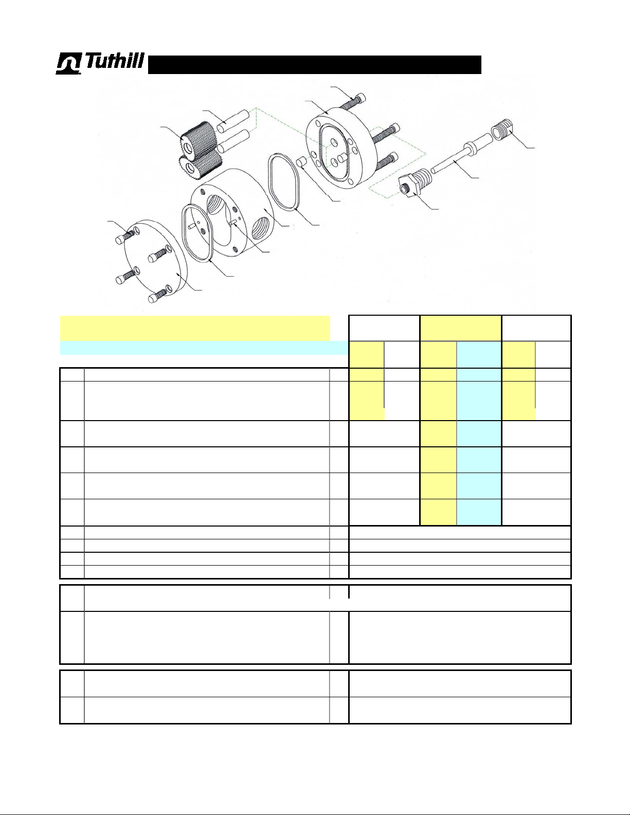
#12
A
TM06A, TM06C & TM06D Parts List
#6
#4
#4a
#9
#11
#2
#3
#8
#5
#10
#7
#5
#1
:
2009
400 PSI (28 B AR) version being p hased out
:
2010
303SS/1500 PSI versi on b eing phased out
303SS/2500 PSI special production, availability subject t o min. qty.
REF Description QTY 28 BAR 103 BAR 103 BAR 173 BAR 28 BAR 103 BAR
1.
Meter c over plate 1 CP2502 CP2508 CP9415 CP8404HP CP9404 CP9415
2.
Screw , cover plate (1/4-20 x 1/2 SHCS) 4 FS9812 FS9812
Screw , cover plate (1/4-20 x 5/8 SHCS) 4 FS1802 FS1802 FS1802
8FS1901
3.
Meter body , 3/4" NPT ports 1 MB8400 MB8400HP
Meter body , 3/4" BSP ports MB8401 MB8401HP
Post plate assy (must be replaced as a set),
4.
consists of Post plate (NSS) & 2 Posts (NSS)
5.
O-ring, cov er & post plate, Viton 2 na na
O-ring, cov er & post plate, Teflon SL2138 SL2138
6.
Screw , post plate (1/4-20 x 1.00 SHCS) 4 FS9832
8FS1901
7.
Dow el pin, cover plate/meter body 2
8.
Dow el pin, post plate/meter body 2
9.
Lock nut 1
10.
Sensor w ell 1
TM06A
nod. Aluminum303 Stls. Ste el
400 PSI 1500 PSI 1500 PSI 2500 PSI 400 PSI 1500 PSI
MB2600
MB2601
CP260111
SL1138 (std.)
SL2138 (opt.)
FS2800
TM06 C TM06D
CP84081
CP8402HP1
MS2001
MS902118-8
MP2541
MP8550
316 Stls . Ste e l
MB9401
MB9402
CP96011
na
SL2138
FS9832
Hall Effect s ensor (pulser).
11.
When used with non-FPP electronics, a PIA-300 signal conditioner is often required.
12.
Low Viscosity/Temperature Nom. 405 PPG (107 ppl) 1 GS550RC380 (std. 2009+)
Gear Nom. 203 PPG (53.5 ppl) GS550RC190 (std. pre-2009)
Set High Temperature ( or high viscos ity) Nom. 405 PPG (107 ppl) GS550RC380-MV (optional)
Nom. 203 PPG (53.5 ppl) GS550RC190-MV (optional)
11.
Reed Sw itch sensor (pulser),
For use with FPP battery powered electronic register
12.
Low Viscosity/Temperature Nom. 101 PPG (27 ppl) 1 GS550RC95 (optional)
High Temperature (or high viscosity) GS550RC95-MV (optional)
K Factor (pulse resolution) is nominal
subject to up to 3-4% shift on liquids w ith viscos ity > 100 cSt.
. Individual flow meters vary, and are
1 EL5581-HPHE
1
2 . 4
EL5581-HPRS
(optional)
M M 06P 2009-11
Page 21
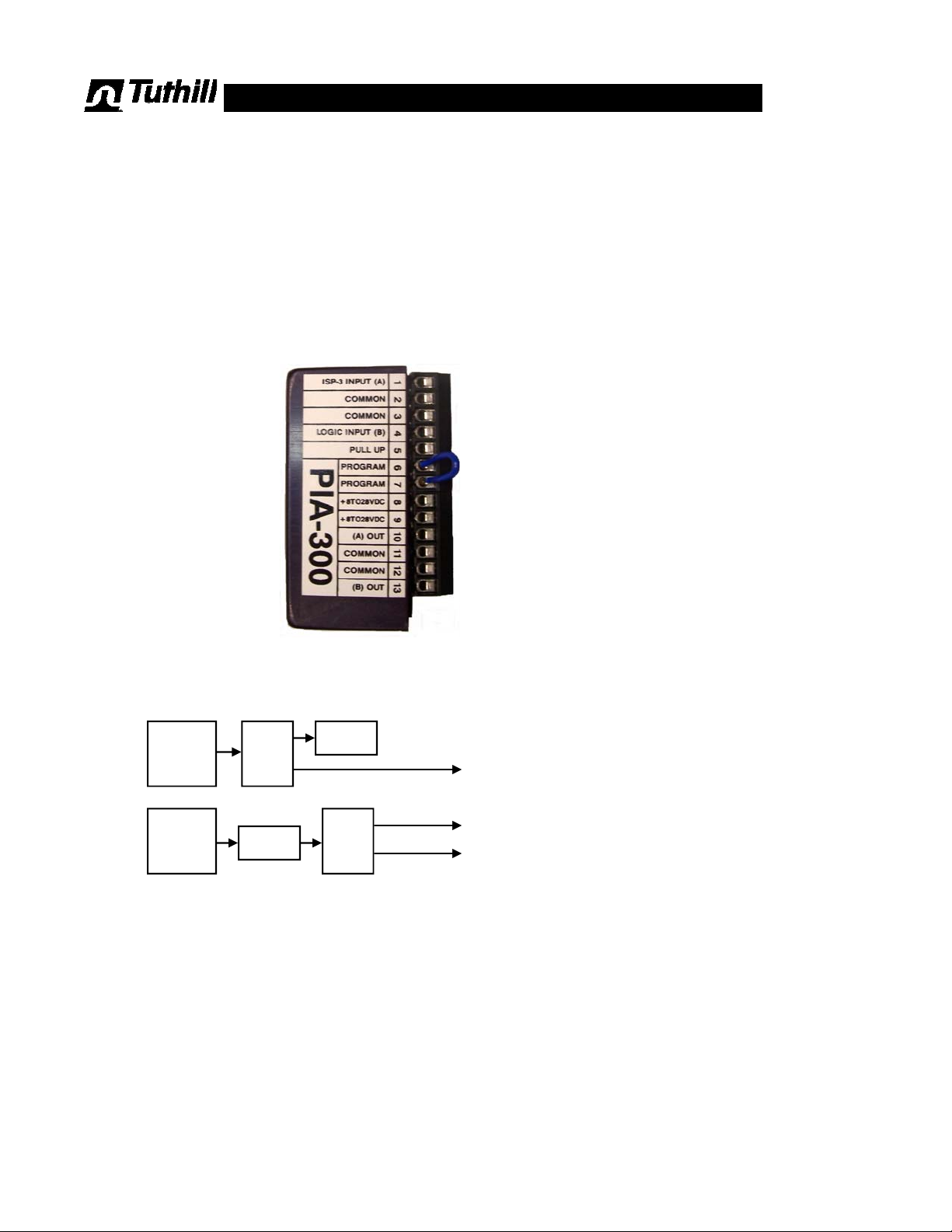
PIA-300 Pulse Isolator, Amplifier & Splitter (optional component)
The purpose of the PIA-300 is to provide:
Protection and properly interface the signal from the Hall
Effect sensor (pulser) to customer supplied electronics
(totalizer, register, PLC, etc.).
Supply SOURCE signal in place of standard sink.
Amplification of output signal, so it can be transmitted
over greater distances.
Two identical output signals, which can be sent to two
different destinations.
This component can be supplied either unmounted (as an
encapsulated circuit pack), or installed in a variety of optional enclosures. In some cases it can be mounted internally in
the remote receiving instrument.
1 ISP-3 INPUT (A)
2 COMMON
3 COMMON
4 LOGIC INPUT (B)
5 PULL UP
6 PROGRAM
7 PROGRAM
8 +8 TO 28VDC
9 +8 TO 28VDC
10 (A) OUT
11 COMMON
12 COMMON
13 (B) OUT
The PIA-300 is often used in conjunction with PC58 or
PCDT58 to provide a pulse signal. In those systems, the
PIA-300 can be wired in one of two positions:
A:
B:
A = High frequency, non-scaled pulse signal to the remote
instrument (raw meter signal).
B = Low frequency (max. 8 Hz), scaled pulse signal from
the register/totalizer to the remote instrument.
HE
PULSER
HE
PULSER
PIA
300
PC58
PC58
PIA
300
P/No. EL6630
Specifications
Input Signal Device : Hall Effect sensor (pulser)
Max. input frequency : 0 to 5,000 Hz
Power Supply Range : Filtered DC power required,
8-28 VDC maximum
Customer supplied, 250 mA
Idle Current Draw : 0.10 Amps @ 28 VDC
Max. Current Draw,
Both Channels : 200 mA
Output Signal : 100 mA per channel into
a 0.1
750’ (230 m) 18-20 AWG wire
μf load, sink or source
Connections : 2.4 mm screwdriver terminals
(wire sizes 14-20 AWG)
Temperature : -40ºF/+158ºF (-40ºC/+70ºC)
Dimensions : 2.10” x 0.98” x 0.38”
52.5 x 24.9 x 9.5 mm
Enclosure options : Local NEMA 3R
Local or remote NEMA 4X
Local or remote NEMA 7/4X
3 . 1
Page 22

This page left blank intentionally
3 . 2
Page 23
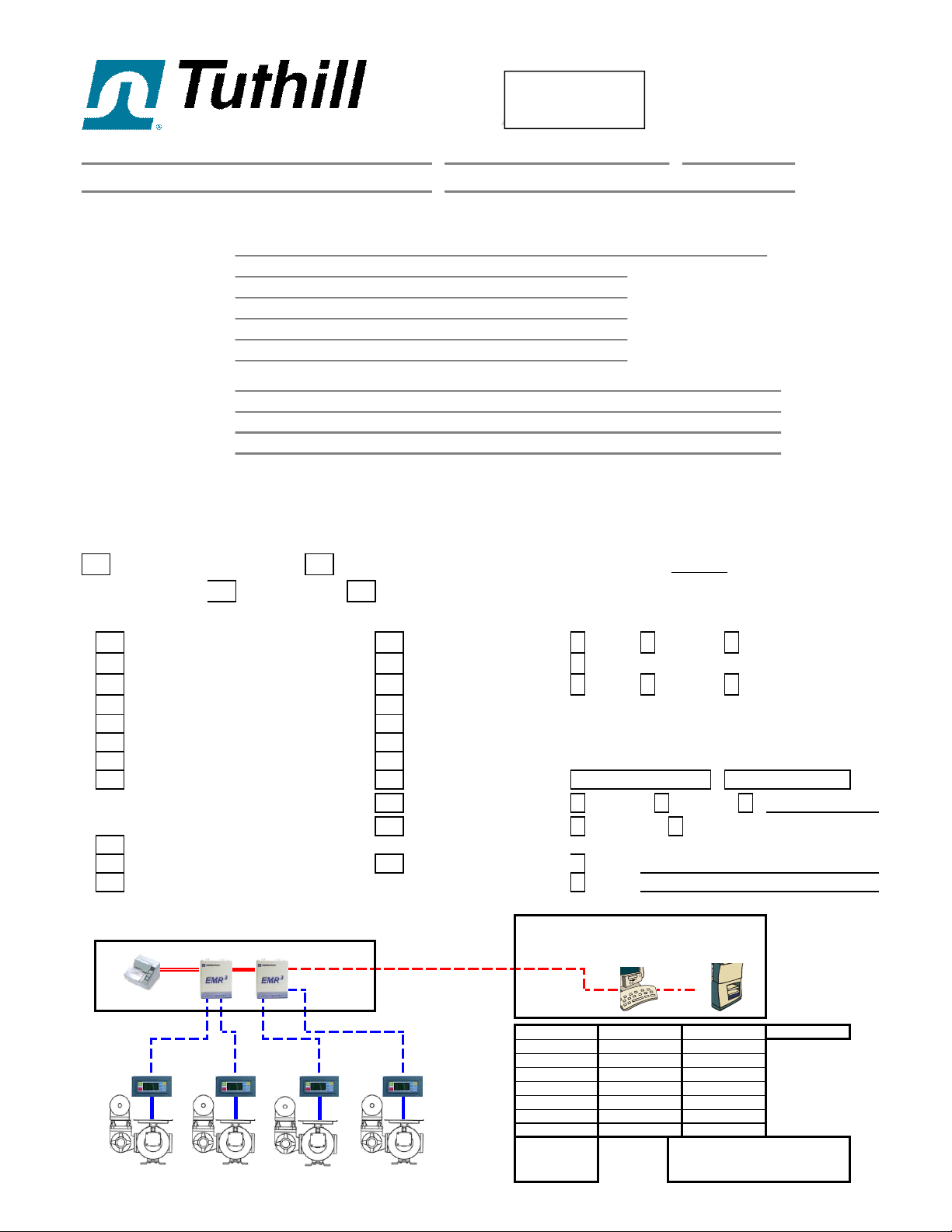
Phn: 260-747-9060
%
r
N
Print
US: 888-578-3258
www.t uth il l. c o m FP P We bInquiries@ tut hill.co m
Name Phone Date
Co mpany E-mail
Fax: 800-866-4861
To ensure correct selection of flow meter and possible accessories, please provide the following details:
Liquid(s) to be metered:
FLOW RATE:
TEMPERATURE:
PRESSURE:
VISCOSITY:
NORM AL M IN: M AX:
MIN: MAX:
NORM AL M IN: M AX:
@ NORM Te m p : @ M IN T e m p :
TYPE of PUMP:
Type of ope ration:
Please describe the
system (such as: Retail
tank truck, rail road
fueling in depot, etc.)
When making a choice betw een mechanical & electronic register , consider that the electr onic system has lower maintenance requirements,
and it is alw ay s more accurate than the equivalent mechanical system due to less drag on the flow meter.
For a single flow meter, the mechanical register is usually the low er initial cost. For 2-3 flow meters in one system/installation, the cost is
usually comparable (w ithin 5-10%). For 4 or more f low meters in one system, the electronic s olution is usually the low er initial cost.
GPM GP H LPM LP H M3/H
°F °C
PSI BAR kg2/cm kP a P a M pa
SS U cS t m m2/ s cP mP a ●S
Circle units used
Custody Transfer service Non-custody transfer, specify accuracy required : +/-
Area class ification: Non-Hazardous Hazardous . Dist ance to ne ar est no n-hazardous location: __________
Accessorie s: Registration, Functions & Communications:
Strainer Register Local Remote Local & Remote
Strainer/Air Eliminator Preset/Batching
Hi gh Capacity Strain er/Air Elim i nato
Pri nter L ocal Rem ote Local & Rem ote
Backpressure Valve R ate o f Flow dis play per MIN HOUR DAY
Air Check Valve Temperature/Volume comp.
Preset Valve, mechanical Currency function
2-stage electronic preset valve Remote operation
1-stage system security valve Pulse signal
Analog signal 4-20 mA 0-20 mA
Flanges:
Transaction data to PC Serial Port Wireless
Threaded companion flanges
Welding companion flanges
without r egister
, specify: Model:
15 0# RF ANSI flang e ad apto rs Voltage:
In mul t i-meter systems wi t h EMR3 regi st er, speci f y d istances:
on-Hazardous & Indoor location
Offic e/Company computer & printer
D
er
with pump control
Resolution/unit: Distance:
other:
b2
b1
a1 a2 a3
IIIIIIIV
b3
b4
a4
etc.
a1 :
a2 :
a4 :
a5 :
a6 :
a7 : b7 :
a8 : b8 :
if regis ter
= 0
is installed o n
flow meter
b1 :
b2 :
b3 :
b4 :
b5 :
b6 :
c1 :
c2 :
c3 :a3 :
c4 :
c5 :
c6 :
c7 :
c8 :
When B OT H lo c al & r emo t e reg ist er,
= the distance fro m interc onnect
C
box to remo te regist er
D :
Page 24
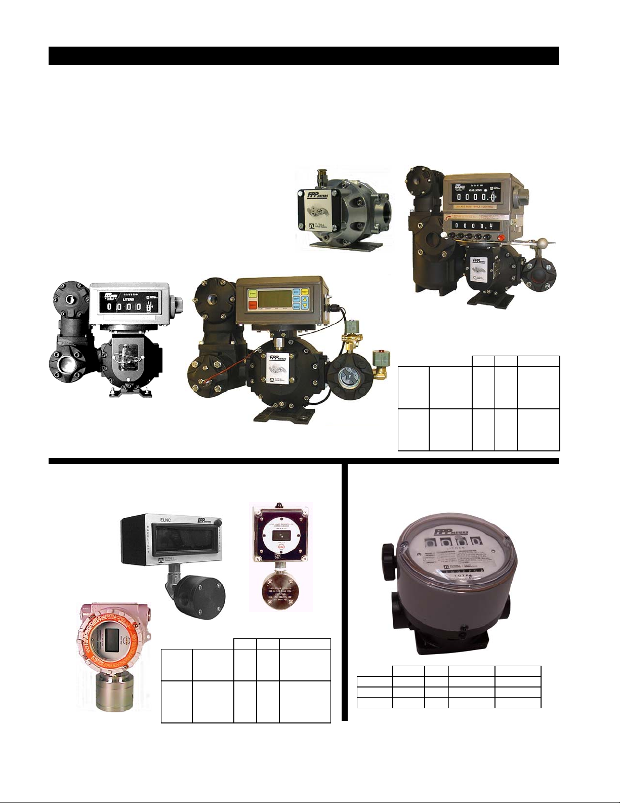
Other TTS Flow Meter Products
Lower Cost of Ownership!
TS20A V06 AL
Also available with mechanical
preset/valve and/or ticket printer
TS Series,
Custody Transfer accuracy,
refined fuels, LPG, heavy fuel oils, glycols, lube oils & petrochemicals
V●● = Mechanical flow meter with mechanical register
F●● = Electronic flow meter with ELNC, EMR³ or for other register
W●● = Gland-less flow sensor (without display)
TS15C W04
TS20A F63 AA2UAS428
Temperature compensated,
with optional solenoid valve
Positive Displacement, oval gear principle
for use on
TS20A V13 ATCBMXAH4
with high capacity strainer,
air eliminator & mechanical preset valve
SIZE GP M PSI
TS10A 1"
TS15A 1½"
TS20A 2"
TS30A 3"
Hardcoat
Anodized
Aluminum
TS10C 1"
TS15C 1½"
TS20C 2"
316SS
TS30C 3"
40 150 & 400
60 150 & 400
150 150 & 400
200+ 150 & 400
40 150 & 400
60 150 & 400
150 150 & 400
200+ 150 & 290
TM Series,
Positive Displacement, oval gear principle, 1/4” - 3/4”
Linearity: ±0.5% with 10:1 turn-down.
TM06A
with ELNC
register
TM04D with
CC56 in NEMA 4X
SIZE GP M PSI
TM06D
with
CC56 in
NEMA 7/4X
TM03A
TM04A
TM06A
Hardcoat
Anodized
Aluminum
TM02D 1/4"
TM03D 3/8"
TM04D 1/2"
316SS
TM06D 3/4"
3/8"
31500
1/2"
10 1 5 0 0
3/4"
20 1500
0.3 1500
3 1500 & 2500
10 1500 & 2500
20 1500
3 . 4
TN Series,
Positive Displacement, nutating disc principle.
The economical alternative with moderate accuracy.
SIZE PSI Viscosity Capacity
TN740A 1"
TN760A 1.1/2"
TN860A 1.1/2"
10 0 0 15 0 + c S t 10 G P M
400 150+ cSt 15 GPM
150 0.7-15 cSt 60 GP M
 Loading...