

Page 1
®
Owner's ManualOwner's Manual
Owner's Manual
Owner's ManualOwner's Manual
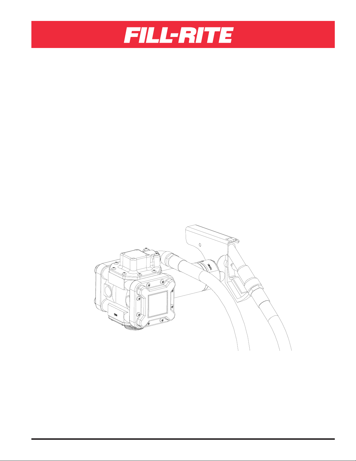
SERIES FR400 DIAPHRAGM
PUMP
For Industrial Fluid Transfer
For models:For models:
For models:
For models:For models:
FR405, FR410, FR412, FR205, FR210, FR212 (DC)FR405, FR410, FR412, FR205, FR210, FR212 (DC)
FR405, FR410, FR412, FR205, FR210, FR212 (DC)
FR405, FR410, FR412, FR205, FR210, FR212 (DC)FR405, FR410, FR412, FR205, FR210, FR212 (DC)
& FR450, FR450E, FR452 (AC)& FR450, FR450E, FR452 (AC)
& FR450, FR450E, FR452 (AC)
& FR450, FR450E, FR452 (AC)& FR450, FR450E, FR452 (AC)
Model FR410
Patent #5,219,274
Page 2
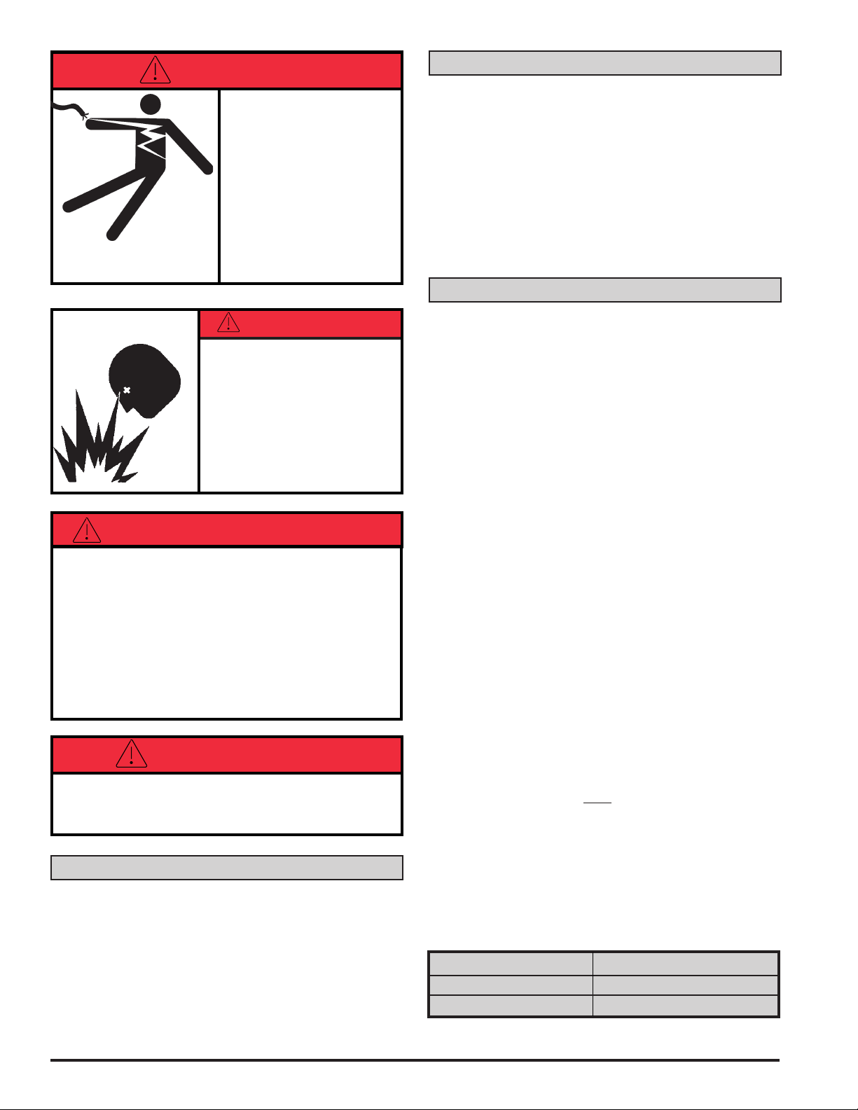
DANGER
EXPLOSION PROOF MOTOR
OPTION: Electrical wiring
should be done by a licensed
electrician in accordance
with approved electrical
codes. Motor should be properly grounded and a rigid conduit should be used when installing electrical wiring. Improper use or installation of
this product can cause serious bodily injury or death.
DANGER
Not for use with fluids thatNot for use with fluids that
Not for use with fluids that
Not for use with fluids thatNot for use with fluids that
have a flash point below 100°Fhave a flash point below 100°F
have a flash point below 100°F
have a flash point below 100°Fhave a flash point below 100°F
(37.8°C, ie: gasoline, alcohol).(37.8°C, ie: gasoline, alcohol).
(37.8°C, ie: gasoline, alcohol).
(37.8°C, ie: gasoline, alcohol).(37.8°C, ie: gasoline, alcohol).
Refer to NFPA 325M (FireRefer to NFPA 325M (Fire
Refer to NFPA 325M (Fire
Refer to NFPA 325M (FireRefer to NFPA 325M (Fire
Hazard Properties of Flam-Hazard Properties of Flam-
Hazard Properties of Flam-
Hazard Properties of Flam-Hazard Properties of Flammable Liquids, Gases, andmable Liquids, Gases, and
mable Liquids, Gases, and
mable Liquids, Gases, andmable Liquids, Gases, and
Volatile Solids) for flashVolatile Solids) for flash
Volatile Solids) for flash
Volatile Solids) for flashVolatile Solids) for flash
points of common liquids.points of common liquids.
points of common liquids.
points of common liquids.points of common liquids.
Static electricity buildup andStatic electricity buildup and
Static electricity buildup and
Static electricity buildup andStatic electricity buildup and
discharge could result in arcdischarge could result in arc
discharge could result in arc
discharge could result in arcdischarge could result in arc
and explosion.and explosion.
and explosion.
and explosion.and explosion.
SAFETY INSTRUCTIONS
1. Use Teflon® tape to seal all joints to avoid leakage
of fluids being pumped. Leaking of caustic and/or hazardous
fluids could result in severe injuries.
2. Never disassemble YOKE ASSEMBLY (see item 12).
This is under extreme pressure and injury could result.
3. Tank or barrel should be anchored to prevent tipping in
both the full and empty conditions.
4. The pump motor is equipped with thermal overload protection. If overheated, it will shut itself off without any
damage to the windings. Be sure to turn off the pump
power if this occurs. As the motor cools, it will start without
warning if power is on.
OPTIONS
•1" polypropylene ball valve/nozzle
•Buna-N or EPDM hose
•Telescoping steel suction tube
• 820 electronic digital meter (for thin or thick
viscosities)
•2" NPT or 2" buttress inlet bung adapter
•1" FNPT straight and 90o inlet/outlet fittings available
•Wraparound tubular mounting frame
•Santoprene diaphragms
•12 VDC, 24 VDC, 115 VAC/60 Hz, 230 VAC/50 Hz
available
TECHNICAL INFORMATION
Design Features
•1" FNPT straight inlet and 90o outlet standard
•15 PSIG maximum outlet pressure
•2600 RPM, 1/4 HP motor:
•12 VDC, rated at 20 amps
•24 VDC, rated at 10amps
•115 VAC/60 Hz rated at 2.0 amps
•230 VAC/50 Hz rated at 1.1 amps
•Thermal overload protection of the motor
•Positive displacement/self-priming design
•Unaffected by particulate materials up to 0.100"
diameter in the pumped fluids
•Flow easily controlled by outlet throttling from
maximum to zero
•Pump may run dry without damage
•Handles viscosities from 1.0 CPS to 3000 CPS
(SAE 140 gear oil at 68
•Minimum shear (agitation) of pumped fluids
•Does not include inlet strainer
•Minimum operating temperature: -10ºF (-23ºC)
•Maximum operating temperature: 130ºF (54ºC)
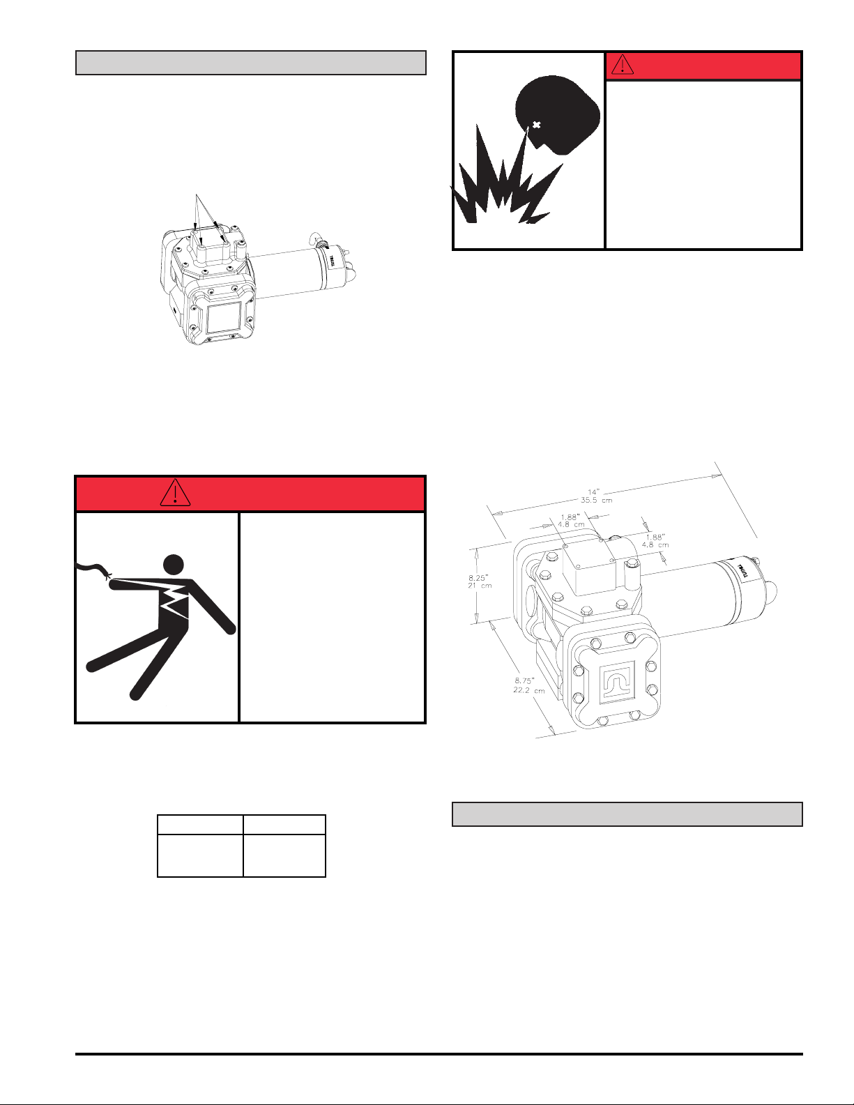
•Overall dimensions: 14" (35.6 cm) long x 8.25" (21cm)
high x 8.75" (22.2 cm) deep
•30 minute duty cycle, not for continuous operation
o
F)
WARNING
This pump should not be used to fuel aircraft. This pump
is not suited for use with fluids for human consumption.
GENERAL DESCRIPTION
The Fill-Rite Series FR400 is a double action diaphragm pump,
using a patented, spring-driven, positive displacement
mechanism. The flow rate with low viscosity material is up to
13 GPM/49 LPM. The ultimate in chemical handling capability
is provided with stainless steel, polypropylene, polyester and
fluorocarbon wetted parts.
Fluid Compatibility
The FR400 Series pump is compatible with the following fluids:
• Ethylene Glycol, Hydraulic Oil, Motor Oil, Water
The FR400 Series pump is
fluids:
NOTNOT
NOT compatible with the following
NOTNOT
• Acetone, Ammonia, Gasoline, Bleach, Chlorine, Hydro-
chloric Acid, Ink, MEK
If in doubt about compatibility of a specific fluid, contact the
supplier of the fluid to check for any adverse reactions to the
wetted materials shown in the parts list.
Fluorocarbon Polypropylene
TM
FilCon
Stainless Steel
Buna-N
2
Page 3
INSTALLATION
The basic pump is furnished with 1" NPT threaded openings in
the inlet and outlet flanges. Flanges are available as a straight
outlet or a 90o angle design, which can be rotated four ways to
accommodate different installation needs. Both inlet and
outlet flanges include four 1/4-20 threaded holes, spaced
1 7/8" between centers, for secure mounting.
Mounting Holes
Adapters are available to fit the pump to a 2" bung and a
selection of standard bung fittings common in the petroleum,
chemical and agricultural markets.
Use pipe compound or Teflon® tape on all threaded fittings
(except 2" bung threads if present).
Electrical Installation
DANGER
Not for use with fluids thatNot for use with fluids that
Not for use with fluids that
Not for use with fluids thatNot for use with fluids that
have a flash point belowhave a flash point below
have a flash point below
have a flash point belowhave a flash point below
100°F (37.8°C, ie: gasoline,100°F (37.8°C, ie: gasoline,
100°F (37.8°C, ie: gasoline,
100°F (37.8°C, ie: gasoline,100°F (37.8°C, ie: gasoline,
alcohol). Refer to NFPAalcohol). Refer to NFPA
alcohol). Refer to NFPA
alcohol). Refer to NFPAalcohol). Refer to NFPA
325M (Fire Hazard Proper-325M (Fire Hazard Proper-
325M (Fire Hazard Proper-
325M (Fire Hazard Proper-325M (Fire Hazard Properties of Flammable Liquids,ties of Flammable Liquids,
ties of Flammable Liquids,
ties of Flammable Liquids,ties of Flammable Liquids,
Gases, and Volatile Solids)Gases, and Volatile Solids)
Gases, and Volatile Solids)
Gases, and Volatile Solids)Gases, and Volatile Solids)
for flash points of commonfor flash points of common
for flash points of common
for flash points of commonfor flash points of common
liquids. Static electricityliquids. Static electricity
liquids. Static electricity
liquids. Static electricityliquids. Static electricity
buildup and discharge couldbuildup and discharge could
buildup and discharge could
buildup and discharge couldbuildup and discharge could
result in arc and explosion.result in arc and explosion.
result in arc and explosion.
result in arc and explosion.result in arc and explosion.
Circuit Breakers (AC only)
Power to the unit should be supplied from a dedicated
circuit breaker. No other equipment should be powered
from this breaker. Provision must be made to break both
legs of any AC circuit.
Dimensions
DANGER
EXPLOSION PROOF MOTOR
OPTION: Electrical wiring
should be done by a licensed
electrician in accordance
with approved electrical
codes. Motor should be properly grounded and a rigid conduit should be used when installing electrical wiring. Improper use or installation of
this product can cause serious bodily injury or death.
DC ONLY: DC ONLY:
DC ONLY: Connect cable to 12 volt DC power supply as
DC ONLY: DC ONLY:
follows, paying special attention to wire colors:
Pump Cable
Positive Red
Negative Black
CALIBRATION
If a meter is used, calibrate according to the instructions in
the meter’s Owner's Operation & Safety Manual.
If pump is to be mounted on a vehicle, it is recommended
that permanent wiring and connections be made to vehicle
power system which includes a 30 amp slow blow fuse.
3
Page 4
ASSEMBLY/DISASSEMBLY
NOTE: Pump should be thoroughly flushed prior to disassembly.
Motor/Gear Assembly Removal (Refer to exploded
view of pump)
1. If possible, position pump with sight caps (item 30) down.
2. Remove four screws (item 20) and lift out motor/gear
assembly.
3. Drain oil from pump if additional maintenance to pump
is required.
Gear Assembly Replacement
1. Remove six screws (item 25) and pull gear assembly
(item 24) from motor.
2. Pull drive gear (item 27) and key (item 28) from motor
shaft.
7. Install motor (item 1) and gear assembly (item 24). Be
sure gasket (item 26) is in place. Rotate motor until drive
shaft slips in hole in gear assembly. Tighten screws (item
20) to 50 in. lbs. of torque.
8 Fill with approximately 16 ounces of automotive grade
SAE 30W oil through one of the holes for sight caps (item
30).
To further disassemble pump.
9 Remove motor and drain oil, if complete disassembly is
required.
10.Remove four screws (item 19) and lockwashers (item 21)
holding bearing plate (item 17).
11.Remove bearing plate (item 17) and thrust plate (item 16).
12.Remove drive shaft (item 13), bearing (item 14), bearing
ring (15) and yoke assembly (item 12).
Assemble in reverse order. See step #4 through step #8
above for additional assembly instructions.
tighten screws to 50 in. lbs.
Hand start and
DO NOT DISASSEMBLE GEAR ASSEMBLY.DO NOT DISASSEMBLE GEAR ASSEMBLY.
DO NOT DISASSEMBLE GEAR ASSEMBLY. Planet
DO NOT DISASSEMBLE GEAR ASSEMBLY.DO NOT DISASSEMBLE GEAR ASSEMBLY.
gears and ring gear are marked for proper assembly and must
not be altered.
Diaphragm Assembly/
Check Valve Replacement
NOTE: Diaphragm and check valve assemblies can be serviced without removing motor and oil from pump body by
removing one at a time with diaphragm facing up. Care must
be taken not to contaminate oil.
1. Loosen cover (item 4) screws (item 20) slightly and drain
fluid trapped in the pumping chamber. Then remove
screws and covers.
2. Remove retainer screws (item 11) and o-rings (item 42).
3. Remove diaphragm assemblies (items 7, 8, 9 and 10) by
pulling check valves out of pump body, starting with outlet
valves first (item 9 at top of pump).
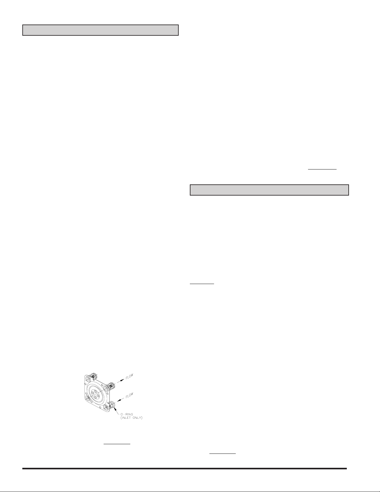
4. Install new diaphragm/check valve assembly, noting ball
location in relation to flow. O-rings are on inlet valves at
bottom of pump. Lubricate O-rings before inserting into
pump body. See Figure #1.
Figure #1
5. Insert four screws (item 11) and o-rings (item 42) into
diaphragm as shown and tighten to 35 in. lbs. of torque.
6. Install pump covers (item 4). Hand start and tighten screws
(item 20) to 50 in. lbs.
MAINTENANCE
To keep pump running at its best, periodically perform the
following procedures. (Refer to exploded view drawing of
pump)
Chemical Applications
Do not allow chemical to remain in the pump for any extended
period of time, whereby the chemicals are allowed to “dry out.”
Thoroughly rinse pump and meter by flushing the pump with
water or appropriate flushing fluid.
DO NOT USE PRESSURIZED WATER OR PRESSURIZED
AIR
to flush your pump. Damage to the equipment can occur
if flush water pressure exceeds 15psi (1 bar). Instead, submerge the suction tube or inlet adapter in clean water and
dispense water by operating the pump. Dispose of the flush
water properly. After flushing, pump air to remove as much
water as possible.
All Applications on annual basis or as needed.
1. Tighten all external screws to 50 in. lbs. (items 19, 20, & 23).
NOTE: NEVER EXCEED 50 IN. LB. TORQUE WHEN
TIGHTENING SCREWS.
2. Drain oil through sight caps and replace oil with
approximately 16 ounces of automotive grade SAE 30W
through one of the sight cap holes. The oil level should be
level with the bottom edge of the sight caps (item 30)
located on the front of the pump body.
NOTE: Always check oil level when the pump is level.
3. Check the four #10-24 x 1/2" machine screws (item 11)
holding the diaphragm in place. If loose, tighten screws to
35 in. lbs. to prevent internal leakage.
NOTE: If external screws (items 19, 20, & 23) are removed,
hand start and tighten to 50 in. lbs.
4
Page 5
REPAIR
Pumps being returned for service must be triple-rinsed
and accompanied by an MSDS sheet indicating the
chemicals/fluids which have been pumped. Pumps not
adhering to these specifications may be refused service
at either the repair shop or the factory.
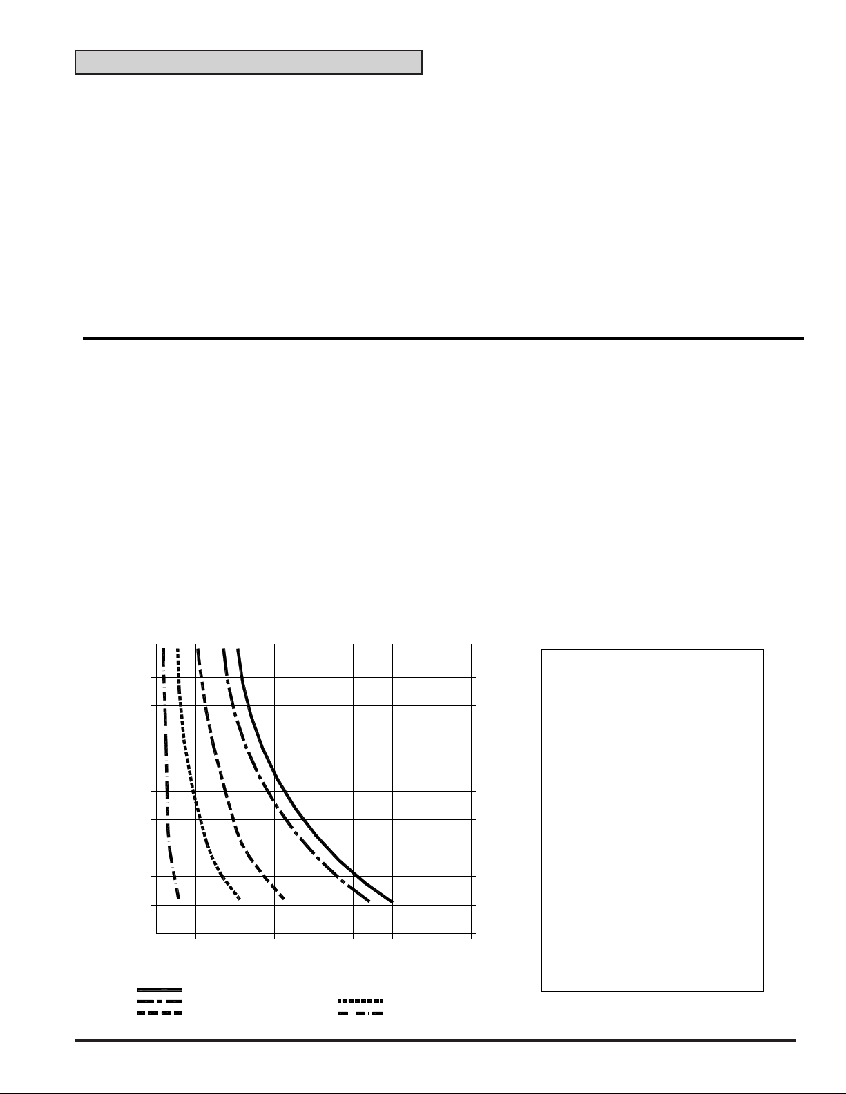
Performance
•Maximum of 30 minute duty cycle, not for continuous operation
•9 inches of mercury dry vacuum
•Suction lift: 10' for water. The lift in feet is equivalent to the vertical distance from the surface of the fluid in the tank.
to the inlet of the pump, PLUS the friction losses through the vertical and horizontal runs of pipe, all elbows and other fittings.
Systems should be designed to require a minimum amount of suction lift.
SERIES 400 DIAPHRAGM PUMP
TYPICAL FLOW RATE FOR VARIOUS VISCOSITIES
FLOW in LITERS PER MINUTE (lpm)
7.6 15.1
0
50
45
)
T
E
E
40
F
(
E
S
35
O
H
E
30
G
R
A
25
H
C
S
I
D
20
D
I
"
1
15
F
O
H
10
T
G
N
5
E
L
0
4 6 8 10121416
2
0
FLOW in GALLONS PER MINUTE (gpm)
225 cps (30 wt Oi l @ 78° F)
308 cps (30 wt Oi l @ 69° F)
560 cps (30 wt Oil @ 56° F)
30.3 37.9 45.4 53 60.6
22.7
15.2
13.7
12.2
10.7
9.1
7.6
665 cps (30 wt Oil @ 49° F)
2420 cps (30 wt Oil @ 22° F)
4.6
1.5
6.1
NOTES:
)
S
1. SUCTION LOSSES.
R
E
T
E
M
(
E
S
O
H
E
G
R
A
H
C
S
I
D
D
I
"
1
F
O
3
H
T
G
N
E
L
0
Test pump was mounted on a 55
gallon drum of oil, 1/2 full. A
SOTERA 1" suction pipe was used.
FILL-RITE
A longer or smaller diameter inlet
pipe will lower the flow rate.
2. VERTICAL HEAD LOSSES.
Test hose was horizontal with
pump. Add 3 feet of hose for each
1 foot of vertical rise.
3. OTHER LOSSES.
Elbows, quick-disconnects,
swivels, and check valves
in outlet or inlet hoses
will restrict the flow.
Add the estimated length of hose
for each component used.
1" SureStop + 0.5 feet
Other 1" disconnects + 13.0 feet
1" Check Valves + 8.7 feet
1" Elbow + 2.6 feet
5
Page 6
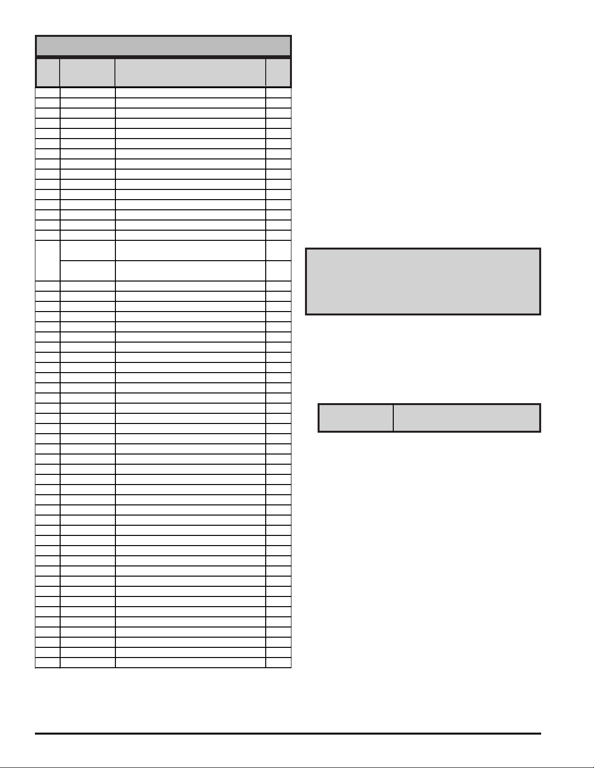
SERIES 400 PUMP PARTS LIST
s
s
F
F
A
ITM. PART
NO. NO. DESCRIPTION QTY.
1a 400G9453 12 VDC Motor no gear
1b 400G9734 12 VDC Motor with gears Opt.
1c 400G9486 115 VAC 60 Hz Motor no gear
1d 400G9735 115 VAC 60 Hz Motor with gears Opt.
2a 400F6846 Motor Assembly - 12 VDC EXP PROO
2b 200G7237 Motor Assembly - 24 VDC EXP PROO
2c 400F7351 Motor Assembly - 115 VAC EXP PROOF Opt.
2d 400G7186 Motor Assembly - 230 VAC EX P PROOF O pt.
3 400F6567 Pump Body 1
4 400F6568 Pump Cover 2
5 400F6569 Flange, straight 1
6 400F6924 Gasket Inlet Flange 2
7 400F6571 Check Valve - Inlet 4
8 35F6588 O-ring (-117) (Included w/Item 7) 4
9 400F6589 Check Valve - Outlet 4
10 400F7238 Diaphragm Assembly - FilCon™ 2
(Includes Items 7, 8, 9)
400F6917 Diaphragm Assembly - Santoprene™ Opt.
(Includes Items 7, 8, 9)
11 400F6795 #10-24 x 1/2 THMS 8
12 400F6781 Yoke Assembly 1
13 400F6800 Drive Shaft 1
14 400F6819 Eccentric Bushing 1
15 400F6827 Bearing Ring 1
16 400F6880 Thrust Plate 1
17 400F6579 Bearing Plate 1
18 400F6693 Shaft Bushing 2
20 400F0267 1/4-20 x 3/4 PHMS 30
21 6U100 Nozzle, Aluminum 1
22 400F6679 90° Flange with brass inserts 1
23 400F6817 1/4-20 x 2-1/4 HHMS 2
24 400F6557 Gear Assembly (Included w/Item 1 or 2) 1
25 400G7494 #6-32 x 1/2 FHMS (Incl. w/Item 1 or 2) 6
26 400F6692 Gasket Motor Flange 1
27 400F6563 Drive Gear (Included w/Item 1 or 2) 1
28 1200F6440 Drive Key (Included w/Item 1 or 2) 1
29 400G9104 Shaft Seal (Included w/Item 1 or 2) 1
30 400F6818 Sight Cap, Polypropylene 2
31 400F6813 O-ring (-022) 2
32 400F8517 Nameplate 1
33 400F6758 Logo Plate 2
34 1200F7207 Cable 20 feet (DC Only) 20 FT
35a 400G9736 Nozzle Holder, Aluminum Nozzle Opt.
35b 400G9737 Nozzle Holder, Poly Nozzle Opt.
36 400F6566 Gear Housing (Included w/Item 1 or 2) 1
37 400G7006 Ball Valve Nozzle, 1", Poly Nozzle Opt.
39 700F3123 1" x 12' EPDM Hose Opt.
400F3140 1" x 12' Nyall Hose Opt.
40 700F6748 Nozzle Cover (Explosive Proof motor) Opt.
41 600F2220 5/16-18 x 3/4 HHCS Opt.
42 400G8887 O-Ring (007) 8
43a 400G9140 Bung Adapter - NPT Opt.
43b 400F6528 Bung Adap ter - Buttress O pt.
44 400F0237
400F7320 Power Cord (115 VAC Only) (Not Shown) Opt.
650G7185 Power Cord (230 VAC Only) (Not Shown) Opt.
400F1855 Suction Pipe, Polypropylene (Not Shown) Opt.
nti-Dr ip Sp out Op t.
1
Opt.
Opt.
Opt.
WHEN ORDERING REPAIR PARTS, BE SURE TO GIVE
REPLACEMENT PART NUMBER, DATE OF MANUFACTURE AND PUMP MODEL NUMBER. THIS WILL
ENSURE THAT THE CORRECT REPLACEMENT PART
IS SUPPLIED.
400KTF6862 Series, 400 Repair Kit
(Includes Items 6-11, 24-28, & 42)
6
Page 7
32
30
DATE STAMP
20
22
3
23
6
13
15
14
16
18
17
5
44
37
39
1b 1d
35a
35b
21
22
31
12
9
10
42
11
4
20
8
7
20
33
EXPLOSION PROOF
MOTOR OPTION
21
43b
43a
19
19
2
12V, 24V, 115V, 230
WITH GEARS
26
25
24
27
28
29
40
41
36
1a
1c
34
20
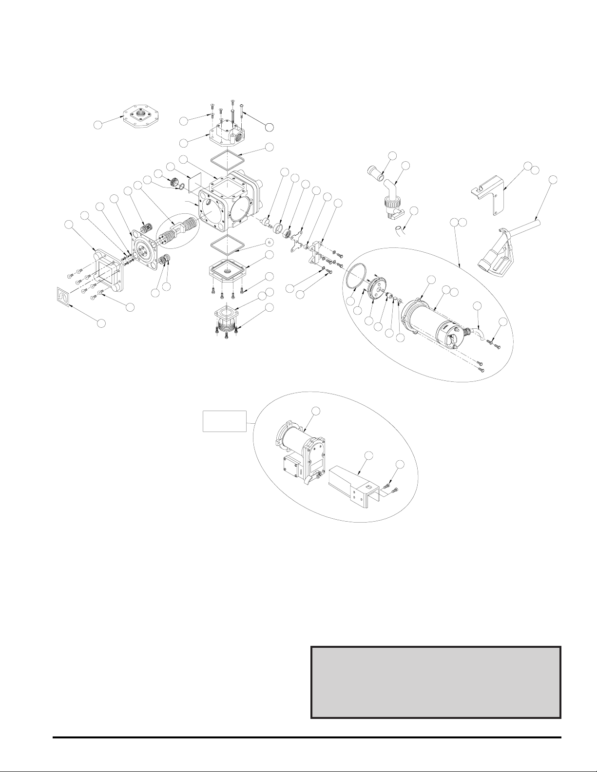
CAUTION:
NEVER disassemble Yoke Assembly.
This is under extreme spring tension
and injury could result.
WHEN ORDERING REPAIR PARTS, BE SURE TO GIVE REPLACEMENT PART NUMBER, DATE OF MANUFACTURE
AND PUMP SERIES NUMBER. THIS WILL ENSURE THAT
THE CORRECT REPLACEMENT PART IS SUPPLIED.
TOLL FREE CUSTOMER CARE NUMBER
800 634 2695
7
Page 8
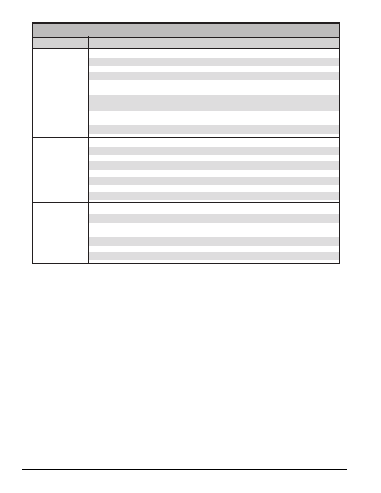
TROUBLESHOOTING GUIDE
PROBLEM POSSIBLE CAUSE SOLUTION
Pump won’t prime •Suction line problem •Check for leaks in suction line.
•Leaky check valves •Check for dirt or damaged check valves and replace.
•Check valves improperly installed •Check for proper installation.
•Outlet plugged •Check for blockage and clear.
•Motor not operating •Check power source.
•Repair or replace motor.
•Stripped or damaged gears •Check gear assembly and drive gear for damage.
Replace complete assembly if necessary.
Pump hums but will •Motor faulty •Replace motor.
not operate •Gear mechanism jammed •Check for free rotation of the gears.
Low pump capacity •Low voltage •Check power source.
•Leaky suction line •Repair leaks.
•Dirt in check valves •Dismantle and clean.
•Faulty check valves •Install repair kit.
•One or both diaphragms leaking •Install repair kit.
•One piston screw loose •Install new yoke assembly.
•Piston retainer screws loose •Install new yoke assembly.
•Debris ingested •Add inlet screen.
Motor overheats •Pumping hot fluids •Shorten duty cycle.
•Motor faulty •Replace motor.
Fluid leakage •Faulty or missing gaskets •Install all gaskets specified in parts list.
•Loose bolts •Torque all bolts to 50 in. lbs.
•Cracked component •Replace defective component.
•Piston retainer screws loose •Install new yoke assembly.
8
Page 9

NOTES
9
Page 10
PRODUCT WARRANTY
Tuthill Transfer Systems (“Manufacturer”) warrants to each
consumer buyer of its Fill-Rite products (the “Buyer”), from the date
of invoice or sales receipt, that goods of its manufacture (“Goods”)
will be free from defects of material and workmanship. Duration of
this warranty is as follows:
• Heavy Duty Products - Two years
• Standard Duty Products – One year
• Economy Duty Products – One year
• Cabinet pumps, Parts, and Accessories - One year
Manufacturer’s sole obligation under the foregoing warranties will
be limited to either, at Manufacturers’ option, replacing or repairing
defective Goods (subject to limitations hereinafter provided) or
refunding the purchase price for such Goods theretofore paid by
the Buyer, and Buyer’s exclusive remedy for breach of any such
warranties will be enforcement of such obligations of Manufacturer.
If Manufacturer so requests the return of the Goods, the Goods will
be redelivered to Manufacturer in accordance with Manufacturer’s
®
instructions F.O.B. Factory. The remedies contained herein shall
constitute the sole recourse of the Buyer against Manufacturer for
breach of warranty. IN NO EVENT SHALL MANUFACTURER’S
LIABILITY ON ANY CLAIM FOR DAMAGES ARISING OUT OF THE
MANUFACTURE, SALE, DELIVERY, OR USE OF THE GOODS EXCEED
THE PURCHASE PRICE OF THE GOODS. The foregoing warranties
will not extend to Goods subjected to misuse, neglect, accident or
improper installation or maintenance, or which have been altered or
repaired by anyone other than Manufacturer or its authorized
representative. THE FOREGOING WARRANTIES ARE EXCLUSIVE
AND IN LIEU OF ALL OTHER WARRANTIES OF MERCHANTABILITY,
FITNESS FOR PURPOSE OF ANY OTHER TYPE, WHETHER EXPRESS
OR IMPLIED. No person may vary the foregoing warranties and
remedies except in writing signed by a duly authorized officer of
Manufacturer. Warranties or remedies that differ from the foregoing
shall not otherwise be binding on Manufacturer. The Buyer’s
acceptance of delivery of the Goods constitutes acceptance of the
foregoing warranties and remedies, and all conditions and limitations
thereof.
400F3394 REV. 8
www. tuthill.com
8825 Aviation Drive
Fort Wayne, In diana USA 46809
Tel 260 747-7524 Fax 260 747-3159
 Loading...