

Page 1

SPL2
Product Manual
Page 2

Page 3

Package Contents
IQ SPL2 Set
1 SPL2 Joint
1 SPC Joint
1 Satellite and Cable
1 Inner Hexagonal Wrench
2 Stickers
2 Cable Clamps
2 Nyloplex Stud with Header
1 Manual
IQ SPL2 Joint
1 SPL2 Joint
1 Inner Hexagonal Wrench
2 Stickers
2 Cable Clamps
2 Nyloplex Stud with Header
1 Manual
IQ SPL2 Unilateral
1 SPL2 Joint
1 Satellite and Cable
1 Inner Hexagonal Wrench
2 Stickers
2 Cable Clamps
2 Nyloplex Stud with Header
1 Manual
IQ SPC Joint
1 SPC Joint
1 Inner Hexagonal Wrench
1 Manual
IQ Satellite
1 Satellite and Cable 1 Manual
3
Page 4
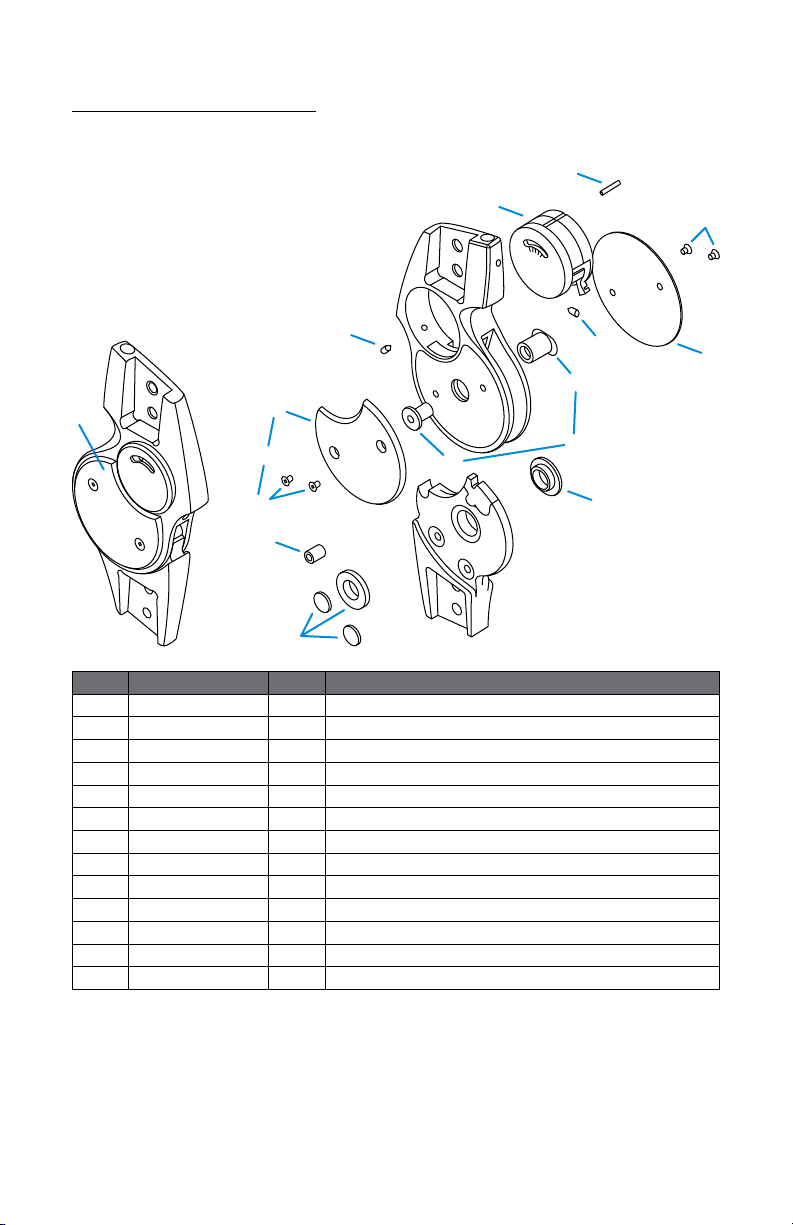
Overview Parts
SPL2 Joint Parts
G
D
3
A
Fig. Part Number Unit Description
A IQ210L or R 1x Swing Phase Lock 2 Joint
B IQ110/03 1x Joint Cover Plate Set
1
B
2
B
3
B
IQ110/03/01 4x Cover Plate Screws
IQ110/03/02 1x Medial Cover Plate
IQ110/03/03 1x Lateral Cover Plate
C IQ110/04 1x Joint Screw and Nut Kit
1
C
2
C
IQ110/04/01 1x Joint Nut
IQ110/04/02 1x Joint Screw
D IQ110/05 1x Set Screw
E IQ210/07 1x Bumper
F IQ110/08 1x Teon Bushing Set
G IQ130L or R 1x Function Unit
H IQ130/01 1x Function Unit Spring Pin
B
B
1
B
2
C
E
F
H
1
B
D
1
C
2
B
C
F
4
Page 5
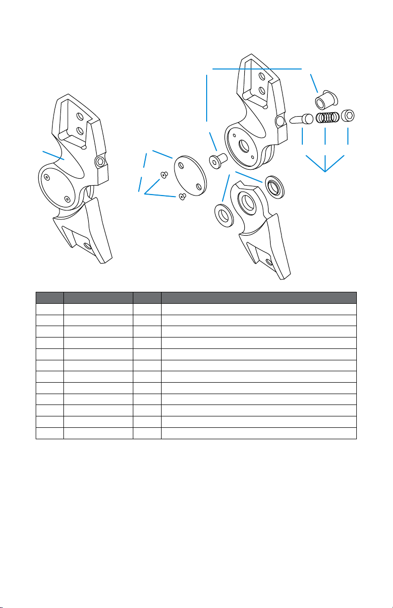
SPC Joint Parts
1
C
2
C
C
2
A
B
B
1
B
D
Fig. Part Number Unit Description
A IQ120L/R 1x Swing Phase Control Joint
B IQ120/03 1x Joint Cover Plate Set
1
B
2
B
IQ110/03/01 2x Cover Plate Screws
IQ120/03/02 1x Lateral Cover Plate
C IQ120/04 1x Joint Screw and Nut Kit
1
C
2
C
IQ120/04/01 1x Joint Nut
IQ120/04/02 1x Joint Screw
D IQ120/08 1x Teon Bushing Set
E IQ120/09 1x Flexion Control Set
1
E
2
E
3
E
IQ120/09/01 1x Flexion Control Bumper Pin
IQ120/09/02 1x Flexion Control Spring Nut
IQ120/09/03 1x Flexion Control Spring
E1E
2
3
E
E
5
Page 6
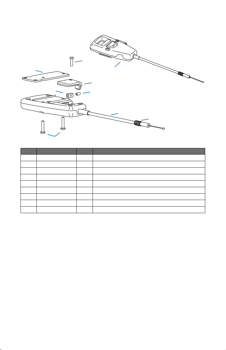
Satellite Parts
D
F
B
A
C
G
H
E
Fig. Part Number Unit Description
A IQ141 1x IQ SPL Satellite Complete
B IQ141/01 1x IQ SPL Satellite Service Hatch Screw 2.2 x 8 mm
C IQ141/02 1x IQ SPL Satellite Service Hatch
D IQ141/03 1x IQ SPL Satellite Mounting Bracket
E IQ141/04 1x IQ SPL Satellite Mounting Plate Screws 2.5 x 12 mm
F IQ140/04 1x IQ SPL Satellite Cable End Block
G IQ140/12 1x IQ Satellite Set Screw for Cable End Block
H IQ141/05 1x IQ SPL Satellite Cable Set
I IQ140/06 1x IQ SPL Satellite Set Screw
I
6
Page 7

Product Specications
Usage of the SPL2 knee joint system provides optimum care for patients
with paresis/paralyses (e.g. polio) and contributes to a successful therapeutic
treatment. This articulating system is meant to compensate weakened or
complete failure of the knee extension function. The joint is available in two
dierent versions: a.unilateral joint or b.bilateral joint.
Indications
SPL2 Orthotic Knee Joint Bilateral and Unilateral
• Apoplexy (CVA) (ICD10: I64)
• Multiple sclerosis (ICD10: G35)
• Myopathy (ICD10: G72.9)
• Paralysis (ICD10: G83.9)
• Paresis (peripheral)
(ICD10: G83.9)
• Poliomyelitis (ICD10: A80)
Contraindications
SPL2 Orthotic Knee Joint
Bilateral
• Flexion Contracture > 10º
(ICD10: M24.59)
• Spasm
• Hip Contracture
• Weight bearing Orthosis (e.g.
quad brim)
SPL2 Orthotic Knee Joint
Unilateral
• Patient weight > 100 kg
• Varus > 10°
(ICD10: M21.10/Q74.9)
• Valgus >10°
(ICD10: M21.00/Q74.9)
• Flexion Contracture > 5º
• Spasm
• Hip Contracture
• Weight bearing Orthosis
Warranty Period
12 months from date of patient tting
Note: The satellite/remote control is not covered under warranty. The warrant y will be
void if the item has been fabricated or installed outside Fillauer ’s recommendations, if
the item has been exposed to a corrosive environment, or if the item has been used in
extremely abusive activities that could result in injury.
7
Page 8

Important Terms and Usages
The SPL2 joint oers knee stability during stance and oers free movement
of the knee during swing. This feature is fully automatically activated with
each step. It is prohibited to be used in water or exposed to temperatures
exceeding 122°F (50°C).
Correct application, in combination with the satellite in the orthosis, is
mandatory. The joint system has been designed only as a non-weight bearing
joint (KAFO/KO) and should not be used in any weight bearing orthoses. Nonobservance of these regulations excludes any liability claims.
Important: The patient must be well informed concerning the functions and possibilities
of the knee joint system, including the satellite/remote control.
Function
SPL2 Technical Features
The technique of the SPL2 (Swing Phase Lock) joint is based on a simple
internal pendulum mechanism, which locks and unlocks the knee depending
on the angle of the knee joint in the sagittal plane. During gait, the device
locks at the end of swing phase, just prior to heel strike, and unlocks the
knee at heel o in preparation for swing. The joint cannot be unlocked if it is
loaded in exion.
SPC Technical Features
The technique of the SPC (Swing Phase Control) joint uses friction to regulate
or inuence excessive knee exion. The moment to full exion is somewhat
shortened and slightly variable.
The SPC joint is always to be mounted on the medial side and is suitable for
¾in. (19 mm) uprights. The joint weight is 6.7oz. (190 grams).
8
Page 9

Satellite Technical Features
The SPL2 joint is controlled by a proximal
remote push-button switch. The satellite is
mounted to the thigh part of the orthosis
with the mounting bracket that is supplied
in the packaging.
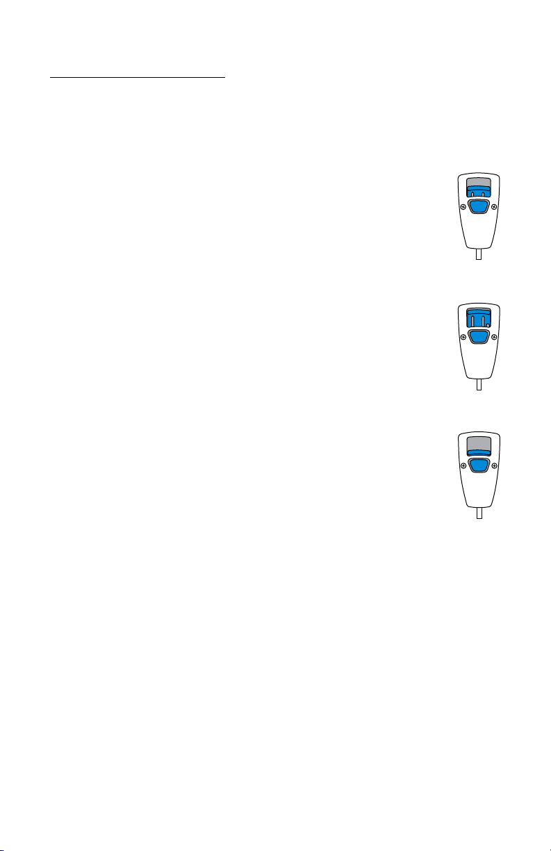
The three modes to manually control the SPL2 joint are:
1. Automatic locking/unlocking
2. Permanent unlocking/free motion
3. Permanent locking
By deactivating the permanent unlocking/free motion mode the satellite
switches into the permanent locking mode and needs to be raised into the
automatic function (Mode 1).
1. 2. 3.
Cleaning & Disinfection Instructions
The SPL2 joint may not be greased, oiled, or lubricated in any way. To clean,
use naphtha or similar cleaning uid or compressed air. Do not use acetone,
dilutions or turpentine, etc.
Maintenance Instructions
Maintenance cycles depend strongly on the patient’s activity level. At a
moderate activity level, the joints must be checked or serviced every six
months. When doing this, attention must be paid to wear and tear, joint play,
and damages. If the joint is no longer working freely, a thorough service is
recommended.
If the joint has been heavily loaded in a exed position, e.g. with stumbling,
tripping, or walking (falling) down the staircase, the joint has to be inspected
by the orthotist. If the patient walks constantly with a slightly exed knee or
regularly uses the safety stops, adjustment of the extension position towards
exion is absolutely necessary.
9
Page 10

Casting and Fabrication Instructions
Component Construction
SPL2 Joint: Housing: stainless steel
Function unit: brass
Cover plates: ABS plastic
SPC Joint: Housing: stainless steel
Cover plates and bumper pin: ABS plastic
Satellite: Housing: ABS, POM plastic
Cable: Teon
Measuring
Casting must be done with a fully neutral extended leg. Stretching, however,
should be possible without too much eort to allow full extension (needed to
unlock the joint) once the orthosis is worn.
When the alignment unit is used (IQ150) to construct the orthosis, make sure
the square with the T-bar is placed horizontal in the frontal plane to keep
the axis straight. Alignment should be based on the plumb line to create a
neutral baseline for the function unit.
Orthosis Construction
Any type of construction is suitable, as long as sucient torsion rigidity and
possibility of changing the exion position during the initial tting is taken
into account.
When the joint is used in a carbon ber-reinforced construction, the SPL2
should be disassembled by removing the satellite. Disconnect the cable
within the function unit (G) and loosen the IQ set screws (D), loosen the
adjustment screw, and gently pull the cable from the housing. Now the
function unit (G) can be pushed inside and removed.
The SPC exion Control Unit must be removed (E) and sealed with stick wax
to prevent improper resin ow. In this case, the upright spacer (029860) can
be used and aligned, allowing the Joints to be mounted in a later stage.
10
Page 11
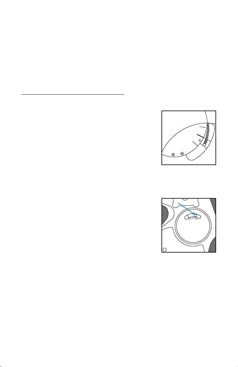
Joint Alignment
The alignment unit must be parallel to the plumb line. The SPC joint should
not be aligned in full extension. If the joint is aligned without using the unit,
the cover plates (B) may be removed allowing the joint axis to be used for
parallel alignment.
Dynamic Initial Fitting
Function Check
Prior to the initial tting, the proper setting of
the joint needs to be checked.
• The slotted arm of the function unit (G) must
be set in neutral 0 position (Fig. A) when the
satellite is in Mode 1. Adjust the proximal
adjustment screw (F) on the SPL2 as necessary.
• Check to see if the SPL2 joint lock after swing
with the satellite in Mode 1. If it cannot lock,…
Adjusting Locking and Unlocking
Timing settings to lock or unlock can be read or
adjusted by moving the pendulum weight of the
function unit.
Figure A
• Moving the pendulum ANTERIOR (forward),
DECREASES the tendency to lock, because its
weight is shifted forward.
• Moving the pendulum POSTERIOR (backward),
INCREASES the tendency to lock because its
weight is shifted backward.
Figure B
11
Page 12
Satellite Control
The patient needs to be instructed on functionality and how to operate
thesatellite.
Mode 1—Automatic Locking and Unlocking
The slider on the satellite is positioned in the middle. This is
the normal position by which the SPL2 joint automatically locks
and unlocks during walking. In this mode, the joint can also be
unlocked once, by slightly pushing the switch upwards. The
automatic mode is activated again when the joint is fully extended.
Mode 2—Permanently Unlocked
The slider on the satellite is slid upward from the center. In this
mode the SPL2 joint is permanently unlocked. NOTE: When
deactivating the permanent unlocking (by pushing the central
button), the satellite automatically shifts into the permanent
locking mode and thus needs to be slid up into the automatic
locking/unlocking mode.
Mode 3—Permanently Locked
For this purpose the central button on the satellite is to be pressed
for the slider to slid fully down. This is a safety mode in which the
SPL2 joint is constantly locked when in full extension (e.g. at home,
making many turns,etc.).
1.
2.
3.
12
Page 13
Shortening the Satellite Cable
First determine the position where the satellite will
be mounted on the thigh cu of the orthosis in
order to establish the correct cable length. Bear in
mind that the cable should have a slight S-shape.
1. Position the joint in full extension and set the
satellite in Mode 3 by pressing the button on
the satellite. Make sure the joint is indeed
locked.
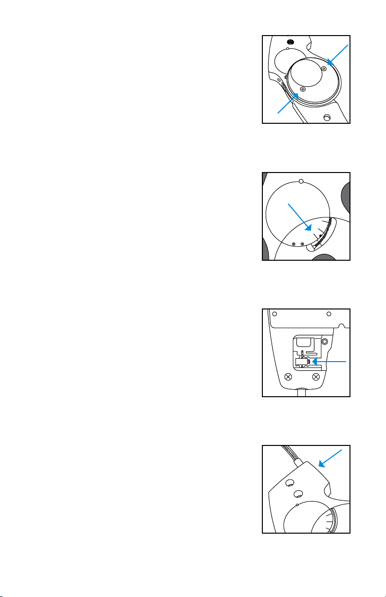
2. Use the supplied hex screwdriver to loosen
the two screws on the medial (stainless steel)
cover plate and remove it (see Fig.1).
3. After removal of the cover plate check if
the upper side of the lever arm (holding the
satellite cable) is parallel to the lower of the
three markers on the function unit (see Fig.2).
4. Using a Phillips screwdriver, loosen the screw
of the service hatch at the back of the satellite
and remove the cover and screw.
5. Use the hex screwdriver to loosen the cone
point safety screw two to three turns and
slide the cable end block o the inner cable
(see Fig.3).
6. Twist the Teon outer cable from the swivel
connector at the bottom of the satellite. Place
the swivel in one hand between your thumb
and forenger and the Teon outer cable
in the other hand between the thumb and
forenger and unscrew (counterclockwise)
the outer cable from the Swivel Connector.
Retract the inner cable outwards through the
swivel.
7. Loosen the cone point safety screw on the
side of the joint two turns (see Fig.4). Do not
remove the screw from the joint.
8. Turn the satellite set screw (which connects
the Teon cable to the joint) completely in
the joint, followed by two complete turns
up again. Trim the Teon outer cable with a
sharp knife to the desired length and remove
DO NOT:
• TAMPER
• GREASE
• OIL
• LUBRICATE
Figure 1
Figure 2
Figure 3
Figure 4
13
Page 14
the excess outer cable. The inner steel cable
will be shortened in step 13.
9. Now slide the inner cable through the bottom
of the swivel connector into the satellite
housing and screw the Teon outer cable
onto the swivel. Place the swivel in one hand
between your thumb and forenger and
the Teon cable in the other hand between
the thumb and forenger. Press and turn
(clockwise) the two parts rmly together (the
swivel is self-tapping).
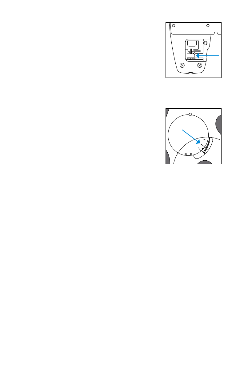
10. Slide the cable end block back over the steel
inner cable and position the end block back
into the corresponding slot in the satellite
(see Fig.5).
11. Recheck the correct position (Mode 3) of the
lever arm in the function unit of the joint (see
Fig.2).
12. Tighten the cone point safety screw of the
cable end block rmly on the inner cable.
13. Use wire cutters to cut o the excess inner
cable at ± 5 mm above the cable end block.
14. Install the service hatch back on the back of
the satellite and reattach the screw.
15. Slide the satellite switch into the automatic
position (Mode 1) and check within the
functional unit of the joint if the top of the
lever arm has moved and now is parallel with
the center marker (see Fig.6).
16. Use the satellite set screw (which connects
the Teon cable to the joint) to ne tune and
adjust the position described in step 16.
17. Tighten the cone point Safety screw back in
the joint (see Fig.4).
18. Mount the medial cover plate back onto the
joint and tighten the screws.
19. Loosen both screws on the front side of the
satellite housing and remove the mounting
bracket.
Figure 5
Figure 6
14
Page 15

20. Determine the exact position where the satellite is to be mounted
on the thigh cu and contour the bracket if necessary. Mount the
mounting bracket on the brace and reattach the satellite using the
screws at the front again.
21. Use the provided cable clamps to attach the satellite cable in order to
ensure an optimal, at resting cable run against the thigh cu of the
orthosis.
Once all the adjustments are done, the opening on the function unit must
be resealed using the IQ sticker. This reduces the likelihood of dirt and
clothing bers getting in.
Checking All Functions
All functions must be checked once again.
1. Do all three modes on the satellite switch reliably?
2. Can reliable locking be achieved with free swing, and is the locking
sucient (is the cable to the satellite on the right length, is the inner
cable in a neutral position, in the 0 position)?
3. Does the joint unlock reliably after the posterior swing?
4. Are the stops all again in position, and does the joint run without play
and smoothly?
15
Page 16

Fillauer LLC
2710 Amnicola Highway
Chattanooga, TN 37406
423.624.0946
Fax 423.629.7936www.llauer.com
M025/09-02-15/01-30-19
© 2018 Fillauer LLC
 Loading...