

Fike SRX, SRL, Axius, ATLAS, AGT SRX Installation And Maintenance Instructions Manual
...
INSTALLATION AND MAINTENANCE INSTRUCTIONS
06-251-1
Reverse Acting Rupture Disc Assemblies
Rupture Disc Models: SRX, SRL, Axius, ATLAS, AGT
Holder Models: SRX, SRL/SRLO, XL/XLO, ATLAS/ATLAS-LO
WARNING
• Read these instructions carefully and completely before
attempting to unpack, install or service the rupture disc
and holder.
• Do not vent a rupture disc assembly to an area where it
would endanger personnel.
• Install the rupture disc assembly in such a way that
equipment in the area will not prevent rupture disc from
opening or be damaged by system discharge.
• A baffle plate on the outlet end of vent piping does NOT
necessarily prevent potentially dangerous discharge.
• Piping should be braced to absorb shock when the rupture
disc ruptures.
• Install the enclosed DANGER sign in a conspicuous
location near the zone of potential danger.
• 1” (DN25) Axius is not suitable for liquid systems at burst
pressures less than 20 PSIG (1.38 BARG) with an inlet
piping length greater than 10 IN (25 cm)
• ¾” (DN20) Axius is not suitable for liquid systems at burst
pressures less than 30 PISG (2.07 BARG) with an inlet
piping length greater than 8 IN (20 cm)
• ATLAS not suitable for liquid systems in sizes 14” and
larger.
• Spiral wound gaskets are not suitable for the following
sizes and flange ratings:
• 1” (DN20 & DN25) – All flange ratings
• 1.5” (DN40) – 900-2500 ANSI and JIS 40k, 63k
• 2” (DN50) – 900-2500 ANSI and JIS 30k, 40k, 63k
• 3” (DN80) – JIS 30k, 40k, 63k
• 4” (DN100) – JIS 30k, 40k, 63k
• If the rupture disc features a fluoropolymer liner, do not
remove this component.
NOTE: Rupture disc specifications and year of manufacture
can be found on the rupture disc tag.
TABLE 1 - DISC/HOLDER MODEL COMPATIBILITY
Disc
Model
SRX
SRL
Axius **
ATLAS
AGT
*1.5" SRL disc not compatible with 1.5” XL/XLO holder
**1.5" Axius disc not compatible with 1.5” SRL/SRLO holder
INSPECTION/PREPARATION
A. NEW RUPTURE DISCS
WARNING: Always handle the rupture disc with extreme
caution. Nicks, dents, scratches or foreign material may result
in leakage or affect the burst pressure. Read the rupture disc
tag completely before installing to confirm that the size and
type are correct for your system.
1. Carefully remove the rupture disc from its packaging
container.
SRX SRL/
Holder Model
XL/
SRLO
XLO
ATLAS-LO
*
ATLAS/
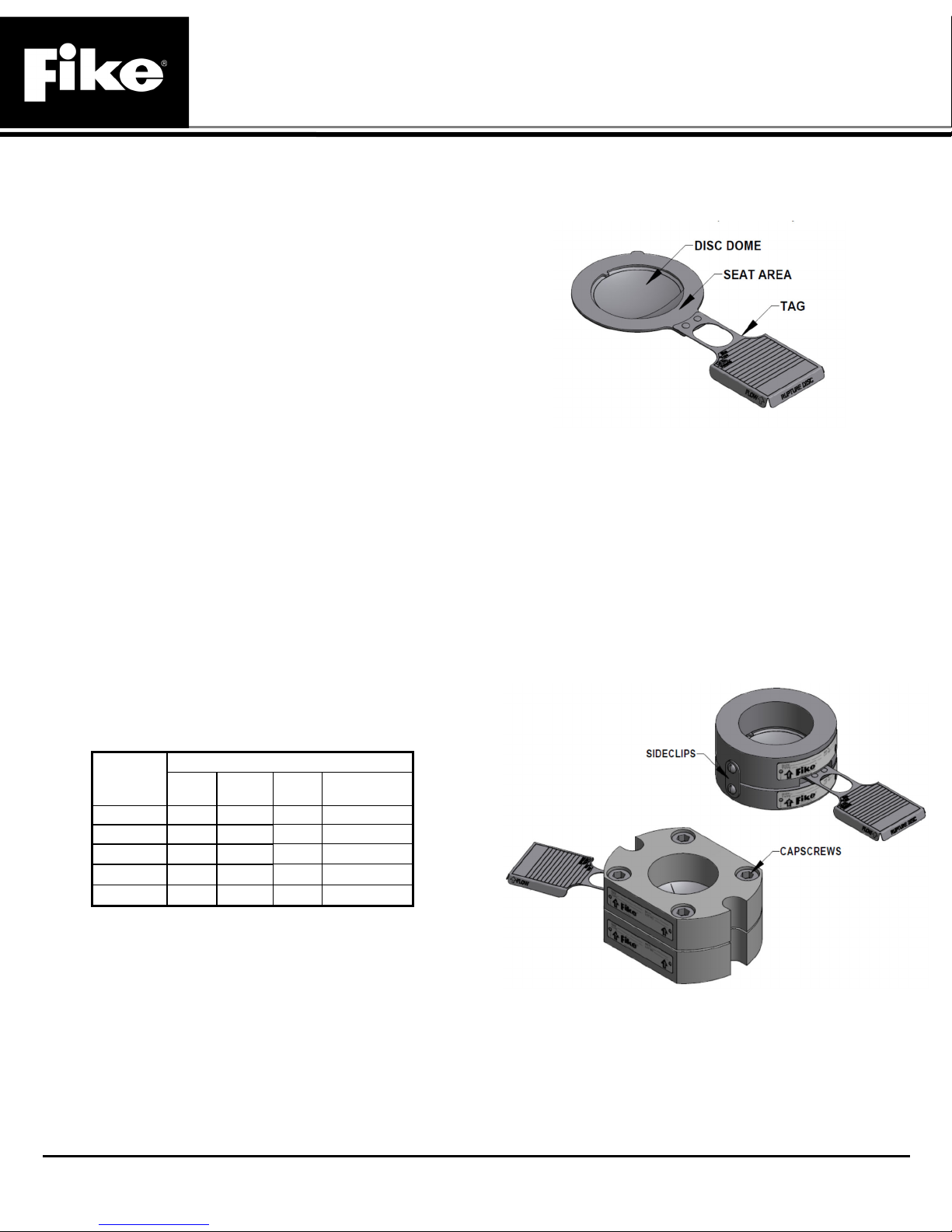
2. Inspect the rupture disc for damage. Look for dents,
scratches or dings in the seat area or dents in the dome of
the rupture disc (See Figure 1).
3. If foreign material is present, carefully clean the rupture
disc with a solvent that is compatible with your media.
Figure 1 - Check for Damage
NOTE: Handle rupture disc holders with care. Damage to
the rupture disc holder could affect the performance of the
rupture disc. Do not install or use a rupture disc that has
been damaged!
B. NEW HOLDER
1. Carefully take the rupture disc holder apart by removing
the sideclips or capscrews and discard the white shipping
protector (See Figure 2).
2. Inspect the seat area for scratches, dents, nicks or dirt.
Flaws may adversely affect sealing and burst pressure.
3. If necessary, clean dust or dirt on the seat area with a
solvent that is compatible with your media.
Figure 2 - Insert Holder (Top) and Pre-torqueable Holder
C. EXISTING HOLDER
1. For insert style holders, carefully remove the rupture disc
assembly from piping.
2. Separate rupture disc holder components.
3. Remove old rupture disc.
4. Inspect the seat area of the rupture disc holder. Look for
scratches, nicks, corrosion or deposits left from the media.
704 SW 10th Street · P.O. Box 610 · Blue Springs, Missouri 64013-0610 U.S.A. · (816) 229-3405 · www.fike.com
Page 1
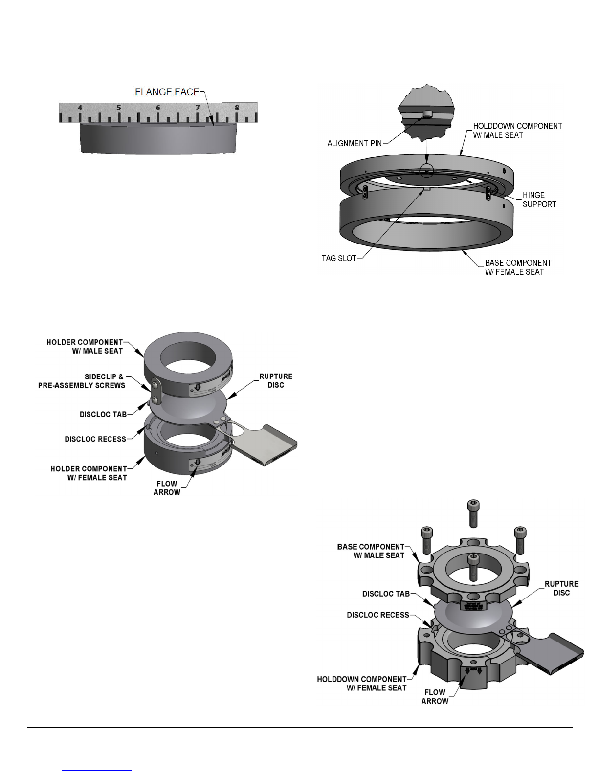
5. Check to make sure the gasket faces of the assembly are
flat by placing a straight edge across the face. If faces are
not flat, holder is not suitable for use (See Figure 3).
CAUTION: Be careful to not allow the male seat
component to strike or damage the dome of the rupture
disc!
Figure 3 - Measuring for Flatness
6. If necessary, clean the seat area with a solvent that is
compatible with your media. If this does not remove dirt,
hand polish the seat area with Scotch Brite fine emery
cloth or #0000 steel wool. DO NOT MACHINE THE
RUPTURE DISC HOLDER! If scratches, nicks, corrosion,
or deposits cannot be removed by hand, contact the
factory.
ASSEMBLY
WARNING: Before attempting to assemble the rupture disc
and rupture disc holder, confirm that the seat area of the
rupture disc is designed to fit the rupture disc holder.
1. Place holder component with female seat on a work
surface (See Figures 4, 5, & 6).
Figure 4 - Insert Holder
2. If the holder was supplied with an optional o-ring groove,
install an o-ring into the groove of the component with the
female seat. Note: Use of an o-ring is for improved sealing
and is not required for proper function of the rupture disc
assembly. Do not install an o-ring unless the holder is
designed to accept these components by Fike!
3. Place rupture disc into holder component with female seat
with flow arrow on tag pointing in the same direction as
holder component with female seat flow arrow.
DiscLocTM tab, if present, must seat properly in recess.
4. If the holder was supplied with an optional o-ring groove,
install an o-ring into the groove of the component with the
male seat. Note: Use of an o-ring is for improved sealing
and is not required for proper function of the rupture disc
assembly. Do not install an o-ring unless the holder is
designed to accept these components by Fike!
5. Carefully align and place holder component with male seat
onto rupture disc with flow arrow in the same direction as
disc and holder component with female seat flow arrows.
Figure 5 – Alignment pin fitting in tag slot. (ATLAS sizes
14” and larger”)
WARNING: For ATLAS sizes 14” and larger, ensure that
the alignment pin in the holddown fits into the tag slot of
base (see Figure 5) and check the gap (see Figure 7).
Fragmentation or leaking can occur if this feature is not
aligned properly.
6. Rotate component with male seat to align sideclip holes.
7. If holder configuration is Insert, install sideclips and tighten
securely.
8. If holder configuration is TQ, turn assembly over to access
capscrew holes (depending on design).
Note: It may be beneficial to move/tilt or support the
holder to first install a few capscrews evenly around the
perimeter before turning the assembly over.
9. If holder configuration is TQ or TQ+, lubricate uncoated
capscrews with a light oil such as SAE grade 20. Lubricate
both the threads and the underside of the head. Install
lubricated capscrews and tighten until recessed and snug
in the holder (see Figure 6).
704 SW 10th Street · P.O. Box 610 · Blue Springs, Missouri 64013-0610 U.S.A. · (816) 229-3405 · www.fike.com
Page 2
 Loading...