

Fike TWINFLEX SRP Engineering And Commissioning Manual

®
TWINFLEX
SRP
Fire Suppression System
Remote Status Indicator (RSI)
(Suitable for TWINFLEX® SRP Control Panel from V01.000)
Engineering and Commissioning Manual
(TO BE RETAINED BY THE COMMISSIONING ENGINEER)
26-1362-01

TWINFLEX® SRP Remote Status Indicator Engineering and Commissioning Manual
Fike’s policy is one of continual improvement and the right to change a specification at any time without notice is reserved. Whilst every
care has been taken to ensure that the contents of this document are correct at time of publication, Fike shall be under no liability
whatsoever in respect of such contents.
Due to the complexity and inherent importance of a life risk type system, training on this equipment is essential and commissioning should
only be carried out by competent persons.
Fike cannot guarantee the operation of any equipment unless all documented instructions are complied with, without variation.
E&OE.
TWINFLEX, Mulitpoint, Fike and Fike Corporation are registered trademarks of Fike Corporation and its subsidiaries. All other trademarks,
trade names or company names referenced herein are the property of their respective owners.
Fike equipment is protected by one or more of the following patent numbers: GB2426367, GB2370670, EP1158472, PT1035528T,
GB2346758, EP0917121, GB2329056, EP0980056, GB2325018, GB2305284, EP1174835, EP0856828, GB2327752, GB2313690
© 2016 Fike Safety Technology Ltd. All rights reserved. Document issued January 2016.
2

TWINFLEX® SRP Remote Status Indicator Engineering and Commissioning Manual
Contents
Introduction ........................................................................................................................................................... 5
System Design ...................................................................................................................................................... 5
Equipment Guarantee .................................................................................................................................. 5
Anti-Static Handling Guidelines .................................................................................................................... 5
Warning ........................................................................................................................................................ 5
EMC .............................................................................................................................................................. 6
The TWINFLEX® SRP System ............................................................................................................................. 6
Remote Status Indicator (RSI) ............................................................................................................................. 6
Mounting the RSI .................................................................................................................................................. 7
Physical Dimensions .................................................................................................................................. 10
General Assembly .............................................................................................................................................. 10
Ribbon Cable Connection .......................................................................................................................... 11
Fixing Front Panel To Back Box ................................................................................................................. 11
Installation and Commissioning ....................................................................................................................... 12
Topology & Cabling .................................................................................................................................... 12
Maximum Cable Lengths ............................................................................................................................ 12
Power Supply & Connections ..................................................................................................................... 13
Power Connection Table .................................................................................................................. 13
Current Drawn by Single Remote Status Indicator @ 24.0V DC ..................................................... 13
Separate Power Supply Requirements ............................................................................................ 13
Remote Status Indicator Back Board Power Supply Connections .................................................. 13
Peripheral Bus Connections ....................................................................................................................... 14
SRP Control Panel Connector Board Peripheral Bus Connections ................................................. 14
Remote Status Indicator Back Board Peripheral Bus Connections ................................................. 14
Ext Switches SW1 and SW2 Connection Examples .................................................................................. 15
RSI With External Switch Connections ............................................................................................ 15
RSI Without External Switch Connections. EOL must be present. ................................................. 15
SRP Control Panel Peripheral Bus Settings .............................................................................................. 16
RSI Panel Settings ..................................................................................................................................... 16
Setting RSI Address/Number ........................................................................................................... 16
RSI Buzzer ....................................................................................................................................... 16
LCD Contrast .............................................................................................................................................. 17
Powering Up ............................................................................................................................................... 17
Commissioning ........................................................................................................................................... 18
Fault finding ................................................................................................................................................ 18
General Operation of Remote Status Indicator ............................................................................................... 19
RSI Front Panel .......................................................................................................................................... 19
LED Indication ............................................................................................................................................ 19
Fire Alarm Controls..................................................................................................................................... 20
System Controls ......................................................................................................................................... 20
Extinguishant Release Controls ................................................................................................................. 20
Access Levels ............................................................................................................................................. 21
Access Level 1 (Normal) .................................................................................................................. 22
Access Level 2 (User): ..................................................................................................................... 23
End User Training ............................................................................................................................................... 25
Maintenance ........................................................................................................................................................ 25
Technical Data .................................................................................................................................................... 25
3

TWINFLEX® SRP Remote Status Indicator Engineering and Commissioning Manual
Remote Status Indicator Specification ....................................................................................................... 25
Fire Alarm System Notice .................................................................................................................................. 26
To Enable the Control Panel Keys ............................................................................................................. 26
To Manually Operate the Fire Alarm Sounders .......................................................................................... 26
Following a Fire Alarm Operation ............................................................................................................... 26
Following a Fault Condition ........................................................................................................................ 26
Important Notes .................................................................................................................................................. 27
Fire Alarm User Notice ....................................................................................................................................... 27
Engineers Notes ................................................................................................................................................. 29
Technical Support .............................................................................................................................................. 30
4
TWINFLEX® SRP Remote Status Indicator Engineering and Commissioning Manual
!
!
!
!
Introduction
This Manual is intended as a guide to the engineering and commissioning principles of the TWINFLEX®
SRP Remote Status Indicator and covers the system hardware information only.
Due to the complexity and inherent importance of a system covering a ‘Life Protection Risk’, training on
this equipment is essential and commissioning should only be carried out by competent and approved
persons. For further details of the availability of commissioning services, please contact your supplier.
System Design
This document does not cover Fire Alarm system design and a basic understanding is
assumed.
A knowledge of BS5839: Pt 1: 2002: Fire Detection and Alarm Systems for Buildings
is essential.
It is strongly recommended that a suitably qualified and competent person is consulted in
connection with the Fire Alarm System design and that the entire system is commissioned
in accordance with the current national standards and specifications.
Equipment Guarantee
The equipment carries no warranty unless the system is installed, commissioned and
serviced in accordance with this manual and the relevant standards by a suitably qualified
and competent person or organisation
Anti-Static Handling Guidelines
Immediately prior to handling any PCBs or other static sensitive devices, it is essential to
ensure that a personal connection to earth is made with an anti-static wrist-strap or
similar apparatus.
Always handle PCBs by their sides and avoid touching any components. PCBs should also
be stored in a clean dry place, which is free from vibration, dust and excessive heat and is
protected from mechanical damage.
Warning
Do not attempt to install this equipment until you have fully read and understood
this manual.
Failure to do so may result in damage to the equipment and could invalidate the warranty.
For technical support please contact your distributor. Do not call the Fike Safety
Technology support department unless your distributor has first given their advice and
attempted to rectify the issue.
Technical support will not be available if the instruction manual has not been read and
understood. Please have this instruction manual available whenever you call for technical
support.
5

TWINFLEX® SRP Remote Status Indicator Engineering and Commissioning Manual
!
EMC
This equipment when installed is subject to the EMC directive 2004/108/EC. It is also
subject to UK Statutory Instrument 2006 No. 3418.
To maintain EMC compliance, this system must be installed as defined within this manual.
Any deviation from this renders the installer liable for any EMC problems that may occur
either to the equipment or to any other equipment affected by the installation.
The TWINFLEX® SRP System
The TWINFLEX® SRP system is an intelligent ‘2-wire’ system utilising a conventional-type cabling
format.
The system is classed as ‘Analogue non-addressable’ due to the architecture used within the design. All
field devices including sounders can be connected to the zone via a common 2-core screened cable.
The devices communicate with the Control Panel using the TWINFLEX® data protocol.
Remote Status Indicator (RSI)
The TWINFLEX® Remote Status Indicator connects to a Control Panel and reports events that occur on
the system. It does not connect to any detection devices.
The TWINFLEX® RSI can also perform fire alarm system controls over the network (i.e. Silence Alarms,
Reset, Sound Alarms & Silence Buzzer). In addition, the RSI can put the system into the Manual
Release ONLY operation mode and it can activate a Manual Extinguishant Release.
A maximum of 8 RSI(s) can be connected to a single SRP Control Panel.
The maximum cable length from the SRP Control Panel to an RSI is 500 metres. If 8 RSIs are used,
they must all be within the maximum 500 metres cable length.
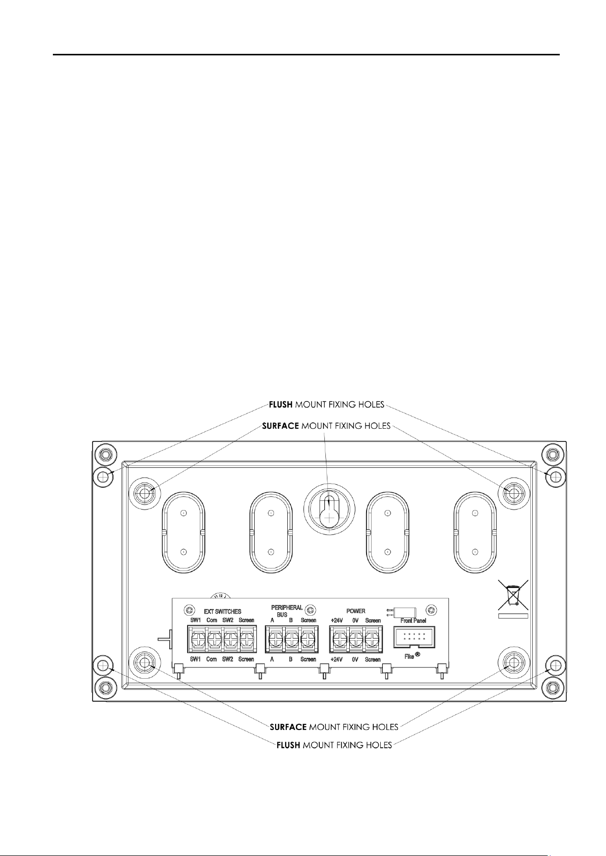
All external connections are made on the back board.
The Ext. Switches SW1 and SW2 are to be used for the external HOLD and RELEASE functions
respectively. SW1 must be a momentary Normally Open switch. SW2 must be a Normally Open
switch. If the Ext. Switches are not going to be implemented, then a 3.3KΩ EOL must be used for
termination.
6
TWINFLEX® SRP Remote Status Indicator Engineering and Commissioning Manual
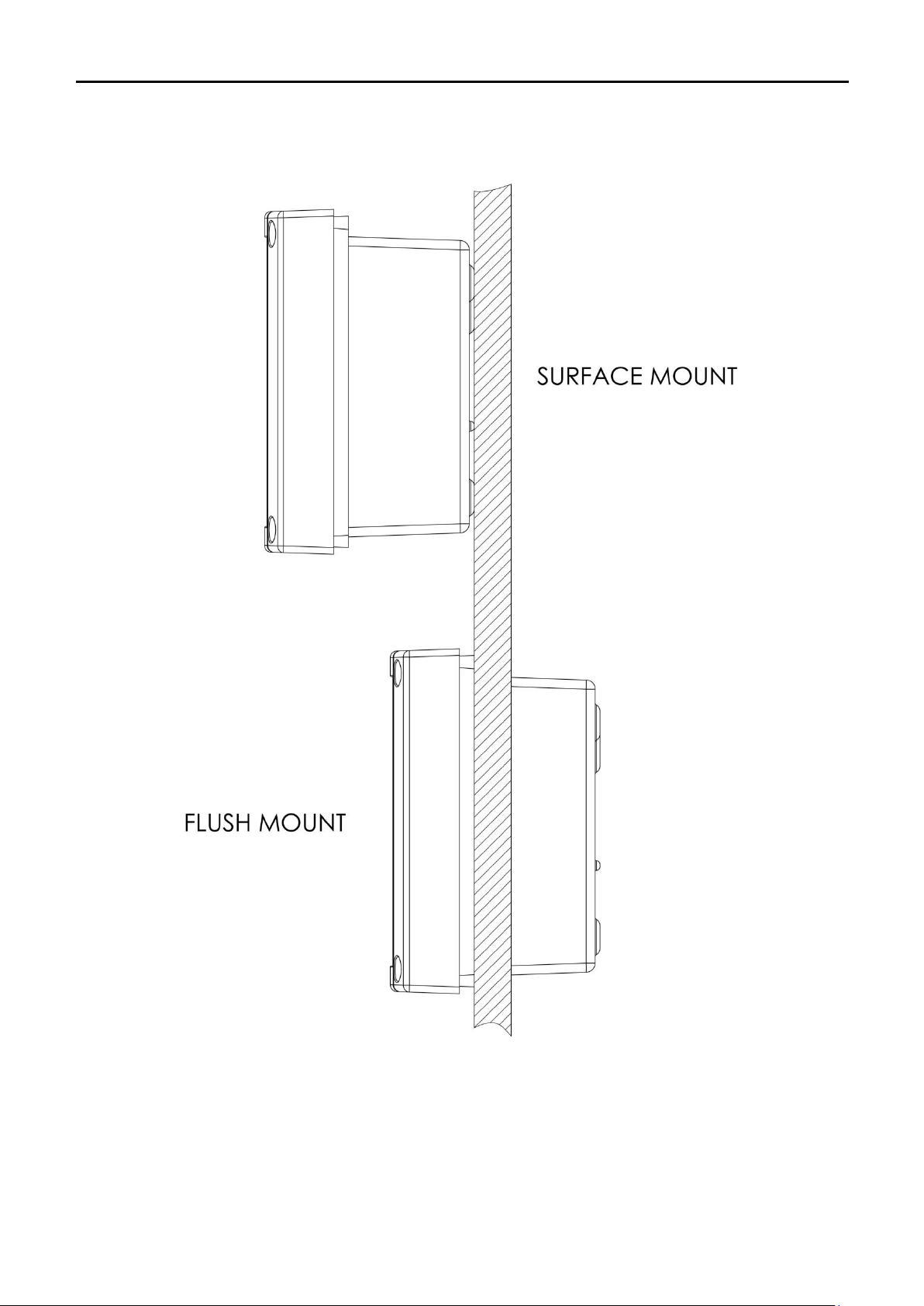
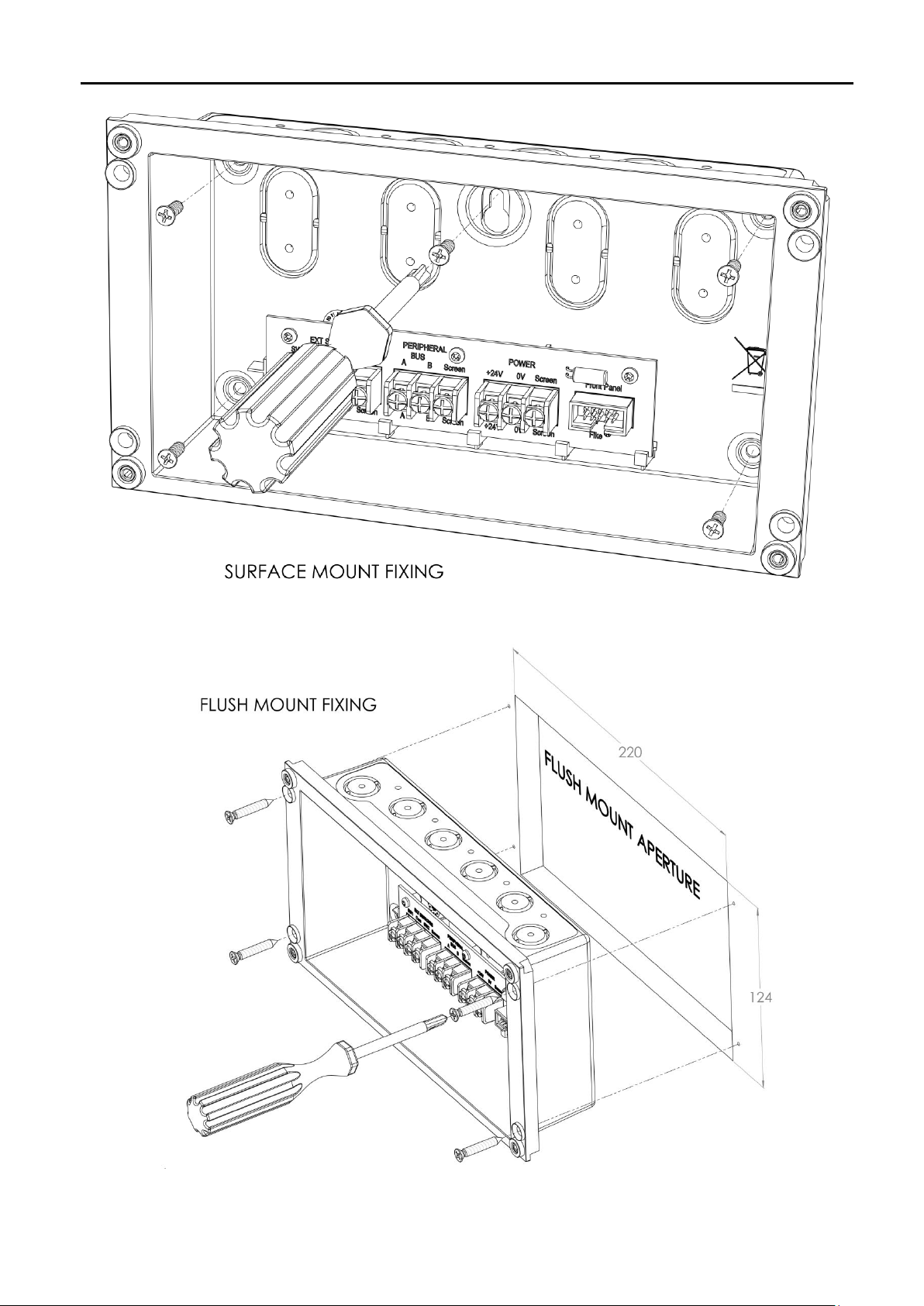
Mounting the RSI
First identify the proposed location for the RSI. Ensure that it will be easily accessible and that account
is taken of any subsequent work that may affect access.
The RSI should be located at an access point to a building which is not covered by the SRP Control
Panel. RSIs can also be located in other buildings which are connected to the SRP Control Panel. It
should be mounted on a flat, vertical wall at a height where the indicators may be seen without difficulty.
Do not locate the RSI at high level where stepladders or other access equipment may be
required, in spaces with restricted access, or in a position that may require access panels to be
removed.
Do not locate the RSI where extremes of temperature or humidity may occur i.e. close to a heat
source, or where there is any possibility of condensation or water ingress.
Like all electronic equipment, the RSI may be affected by extreme environmental conditions. The
position selected for its installation should therefore be clean and dry, not subjected to high levels of
vibration or shock and at least 2 metres away from any pager or radio transmitting equipment. Ambient
temperatures should be within the range given within the “Technical Data” section, e.g. not directly over
a radiator or heater.
In common with all microprocessor-controlled panels, the RSI may operate erratically or may be
damaged if subjected to lightning-induced transients. Proper earth/ground connections will greatly
reduce susceptibility to this problem.
7
TWINFLEX® SRP Remote Status Indicator Engineering and Commissioning Manual
8
TWINFLEX® SRP Remote Status Indicator Engineering and Commissioning Manual
9
 Loading...