

Fike TwinflexPro2 conventional Expansion Card, Twinflex pro 505-0006 Installation And Maintenance Instructions Manual
INSTALLATION AND MAINTEN ANCE
INSTRUCTIONS
Tw i n f l e x P r o ² c o n v e n t i o n a l E x p a n s i o n C a r d 505- 0007
General Description
The TwinflexPro² Conventional Expansion card will provide 4 conventional zones. Therefore a TwinflexPro²
panel fitted with a Conventional Expansion card would have zones 1 to 4 as Twinflex zones and zones 5 to 8 as
conventional zones. The card is only compatible with the 4-zone TwinflexPro² panel. It is not compatible with the
2-zone TwinflexPro² panel or with any earlier TwinflexPro or TWINFLEX® Checkpoint Plus panels.
Note: conventional zones cannot distinguish between smoke or MCP fire signals.
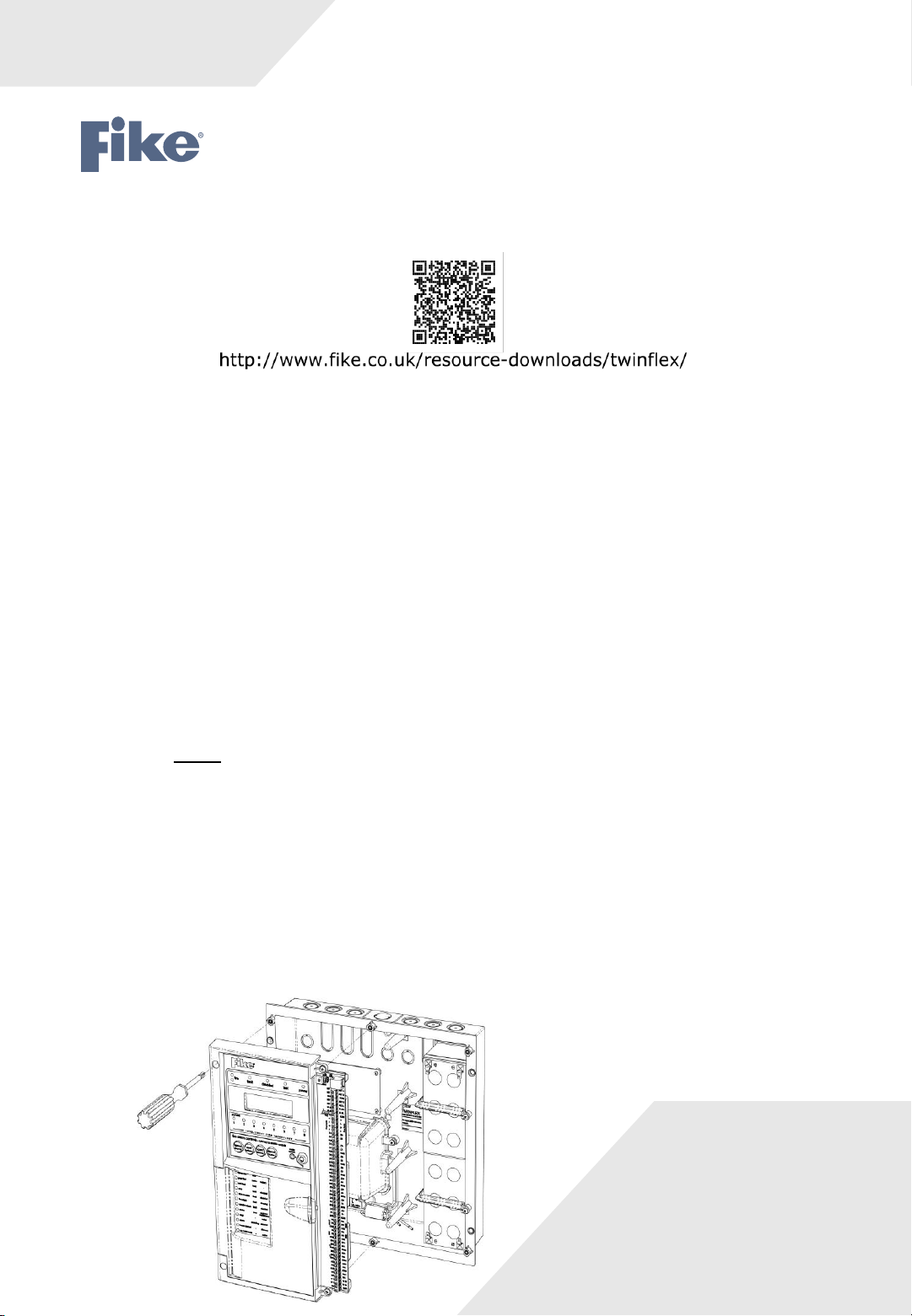
Installation
The panel must be completely powered down before this card is fitted.
1. Remove the right hand cover moulding from the unit by unscrewing the two fixing screws.
2. Next disconnect the battery by removing one of the push on battery leads at the battery. Always disconnect
the battery first before removing the mains power to the panel.
NOTE: Do not disconnect the battery by removing the wires from the terminals on the CIE circuit
board. Doing this may allow the batteries to short circuit.
3. Remove mains power from the panel by removing the fuse in the fused spur that supplies the panel or
switching off the circuit breaker. At this stage there should be no LEDs lit on the panel and the display
should be blank.
4. Disconnect all cabling from the CIE terminals. Make sure these cables are suitably labelled to facilitate
correct re-connection after fitting the Expansion Card.
5. Unscrew the four fixing screws that secure the left hand CIE assembly (Fig 1), then flip the assembly over
clockwise (Fig 2).
Fig 1
26-1509 Issue 2
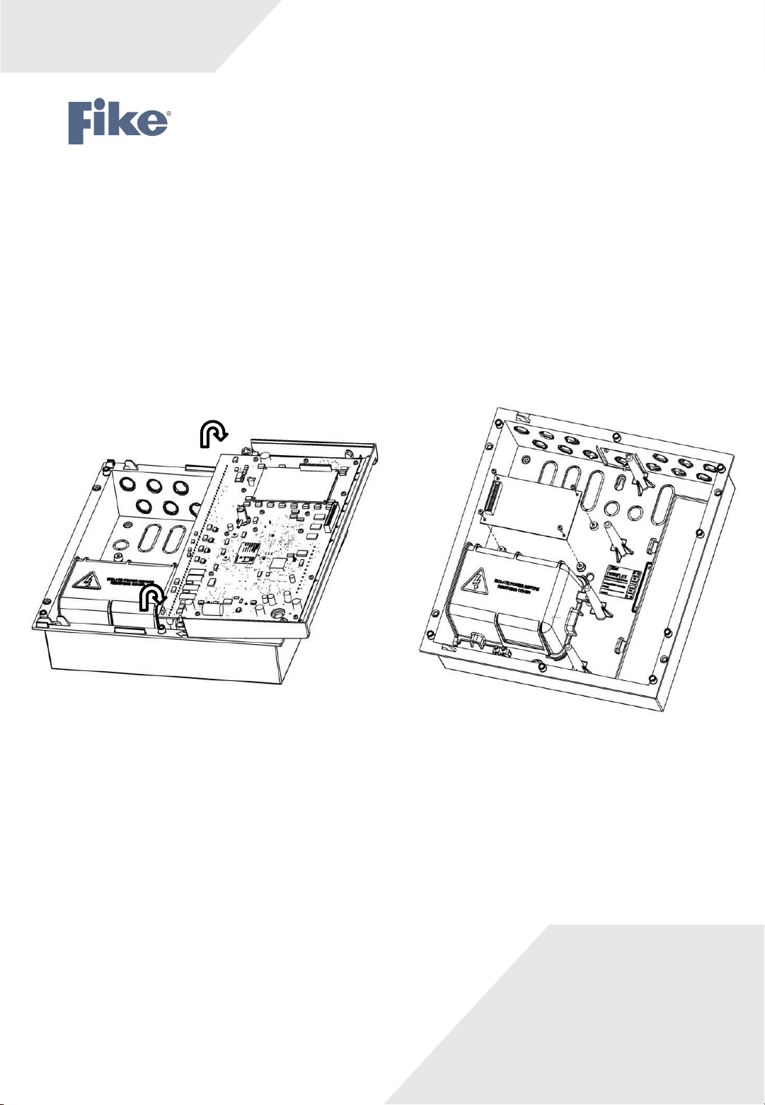
6. Secure the expansion card PCB to the unit’s base using the 4 off M3 x 6 screws supplied
(Fig 3). Please note the orientation of the expansion card PCB.
7. Plug one end of the ribbon cable assembly into the expansion card PCB (this will only fit one way).
8. Flip the left hand CIE assembly back over clockwise (reverse fig 2) and plug the other end of the ribbon
cable assembly into the connector marked (expansion connector) on the CIE PCB (again this will only
fit one way).
9. Secure the CIE assembly onto the base molding (Fig 1) (ensure that all cables ends are accessible for
termination) and secure into position.
Fig 3 Fig 2
10. Re-connect all existing cables to the appropriate terminals.
11. If the new additional zones are to be used straight away, connect the additional field wiring zone cables to
the relevant terminals on the TwinflexPro² panel CIE (they do not connect directly to the Expansion Card).
12. Re-connect the mains power to the panel (before connecting the battery) by refitting the fuse in the fused
spur that supplies the panel or switching on the circuit breaker.
13. Now re-connect the battery.
14. Refit the right hand cover (ensure the cover engages
properly into the CIE assembly moulding) and secure into position.
26-1509 Issue 2
 Loading...