

Page 1
T w i n f l e x P r o ²
R e p e a t e r P a n e l
Q u i c k S t a r t G u i d e
Do not attempt to install this equipment until you have fully read and understood the manual
A knowledge of BS5839: Pt 1: 2017: Fire Detection and Alarm Systems for Buildings is essential.
It is strongly recommended that a suitably qualified and competent person is consulted in connection with
the Fire Alarm System design and that the entire system is commissioned in accordance with the current
national standards and specifications.
Equipment Warranty
The equipment carries no warranty unless the system is installed, commissioned and serviced in accordance
with the manual and the relevant standards by a suitably qualified and competent person or organisation.
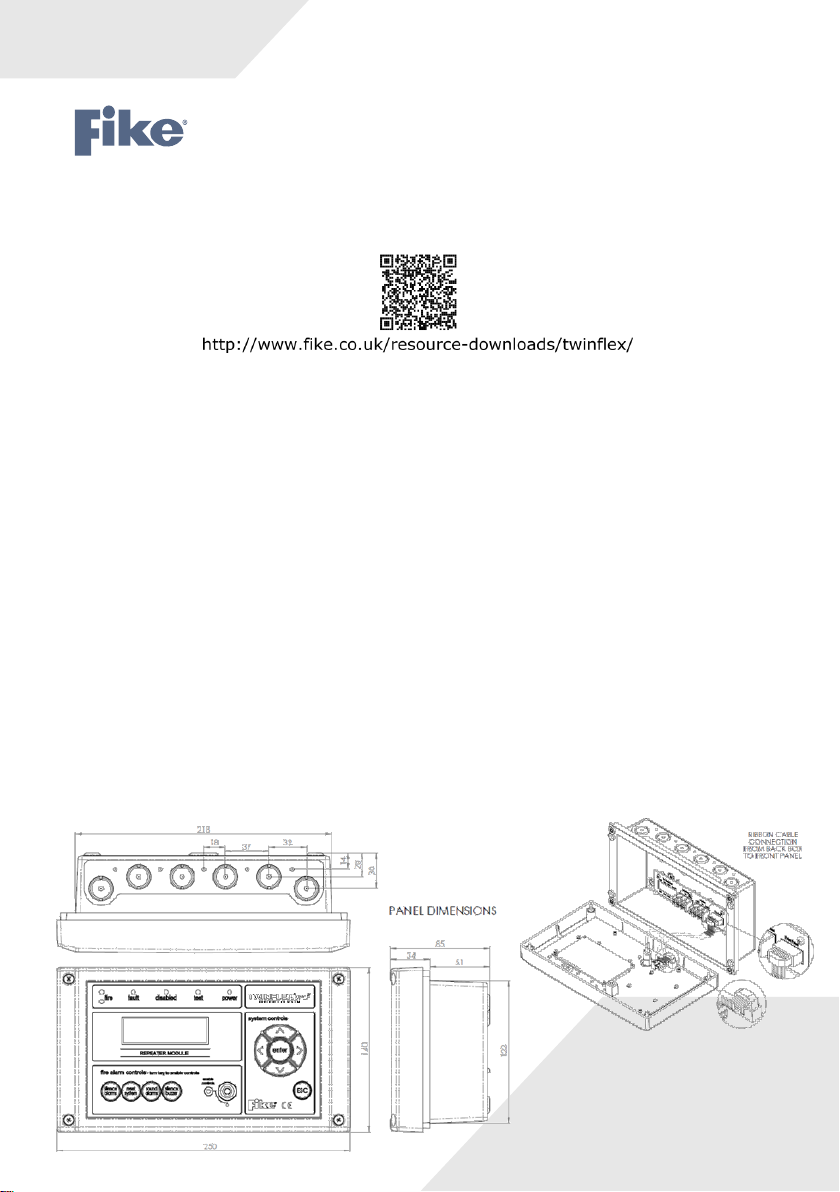
Repeater Panel, Remote Display Unit (RDU)
The TWINFLEX®Pro² repeater panel is smaller than the TWINFLEX®Pro² control panel.
It does not itself connect to or control detection devices. Instead, it connects to a control panel and reports
events which occur on the control panel.
It can also perform system controls over the network (i.e. Silence Alarms, Reset, Sound Alarms & Silence
Buzzer).
A maximum of 8 repeater panels can be connected to a single control panel.
The maximum cable length from the control panel to a repeater is 500 metres. If 8 repeaters are used they
must all be within the maximum 500 metres cable length.
All external connections are made on the back board. The Ext Switches on the back board are not currently
used and are for a future development.
which can be found on our website
26-1703 Issue 1
Page 2

Topology & Cabling
All system wiring should be installed to comply with BS 5839: and BS 7671 (wiring regulations) and any other standards
relevant to the area or type of installation. A cable complying with BS 5839: Pt 1: Category 1 (cables required to operate
for prolonged periods during fire conditions) is required. This must be a 2-core 1.5mm2 screened fire resistant cable (ie.
FP200, Firetuff, Firecell, Lifeline or equivalent).
The maximum total cable length from the control panel to a repeater is 500 metres.
Up to 8 repeaters can be used but they must all be within the maximum 500 metres cable length.
The cable screen must be connected to earth/ground at the control panel only.
The cable screen continuity must be maintained at every point of the circuit, using the terminals provided or a suitable
connection block.
Do not use a 4-core cable as a 24v supply and communications, due to the possibility of data corruption. It is essential
that two 2-core screened cables are used, one for the 24V DC supply and the other for communications.
Power Supply & Connections
24V DC Power is provided from the control panel via Aux+ and Aux-.
2-core 1.5mm2 screened fire resistant cable
When powering a repeater from the panel the extra current will reduce the battery backup run time and has to be
allowed for in the battery calculations.
Current Drawn by Single Repeater @ 24.0V DC
Separate Power Supply Requirements
The repeater can be powered by a separate 24v EN-54 power supply if required.
The repeater working voltage range is between 21V DC to 32V DC with a maximum current of 50.0mA.
Peripheral Bus Connections
Communications between the panel and repeater is via a multi-drop RS-485 Peripheral Bus.
2-core 1.5mm2 screened fire resistant cable ((i.e. FP200, FP200, Firetuff, Firecell, Lifeline or equivalent)
cable should be used for communications to the repeater and connected to the back board.
The peripheral bus must be run from the panel to the first repeater then the second repeater and so on; the peripheral
bus must not be spurred from one point.
26-1703 Issue 1
Page 3
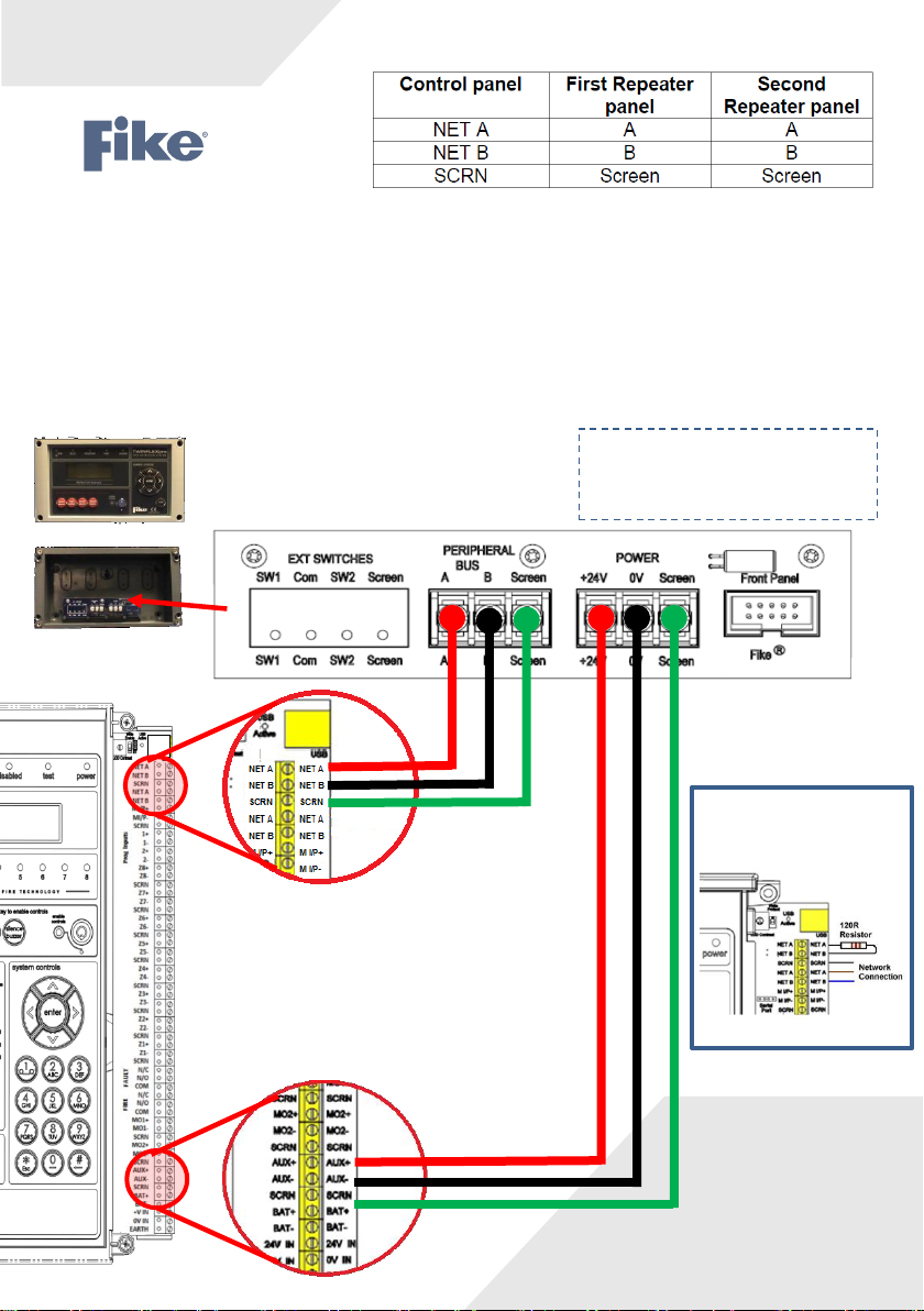
Peripheral Bus Connections
There are two sets of peripheral bus connections on the panel. These are linked in the panel so either set can be
used.
A 120Ω Smoothing resistor must also be fitted across NET A & NET B at the panel.
On the repeater a 120Ω Smoothing resistor must also be fitted across A and B but only on the last repeater on the
network.
Connections
A to A, B to B, Screen to Screen and so on up to the maximum of 8 repeaters.
• MAX CABLE LENGTH 500M
• UP TO 8 REPEATERS PER PANEL
• 120Ω
120Ω Smoothing resistor
may also need to be
fitted
26-1703 Issue 1
Page 4
Technical Data
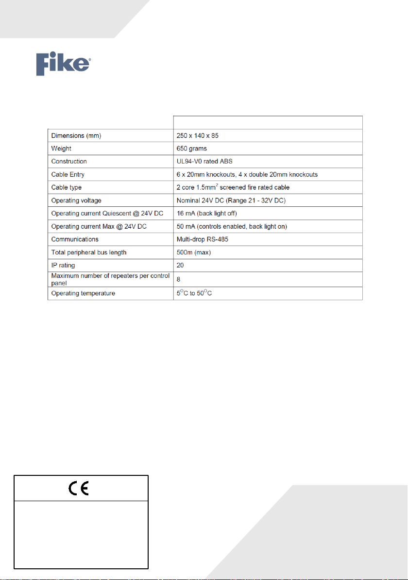
Repeater Panel Specification
Technical Data
For specifications of the TwinflexPro², please see the TwinflexPro² Engineering & Commissioning Manual.
Technical Support
Contact your supplier for technical support on this product.
Due to the complexity and inherent importance of a life risk type system, training on this equipment is essential, and commissioning
should only be carried out by competent persons. Fike cannot guarantee the operation of any equipment unless all documented
instructions are complied with, without variation. This unit complies with the EMC directive.
Fike’s policy is one of continual improvement and the right to change a specification at any time without notice is reserved. Whilst
every care has been taken to ensure that the contents of this document are correct at time of publication, Fike shall be under no
liability whatsoever in respect of such contents. E&OE.
TWINFLEX, Fike and Fike Corporation are registered trademarks of Fike Corporation and its subsidiaries. All other
trademarks, trade names or company names referenced herein are the property of their respective owners.
Fike Safety Technology Ltd
Unit 31, Springvale Ind. Est.
Torfaen, NP44 5BD
Tel: +44 (0) 1633 865 558
13
DoP-505-0010
 Loading...