

Fike Twinflex 302-0023 Installation And Maintenance Instructions Manual
INSTALLATION AND MAINTENANCE INSTRUCTIONS
302-0023 Twinflex
Flashpoint Weatherproof
General Description
The Twinflex Weatherproof Flashpoint device provides visual indication when
the system enters an alarm condition. This device is compatible with the
Twinflex 2-wire range of Fire Alarm equipment and comprises a 2-wire zonepowered visual indication beacon. This device may be installed on the same
zone as the Multipoint detector/sounder and associated Twinflex devices.
Before Installation
The Flashpoint must be installed in compliance with the control panel
installation manual. The installation must also meet the requirements of any
local authority. For maximum performance the Flashpoint should be installed
in compliance with BS5839 Pt1 : 2002 + A2 : 2008.
Spacing
Fike recommends spacing of sounders and strobes in accordance with BS5839 Pt1. For more specific information
regarding spacing, placement and special applications please refer to BS5839 Pt1 : 2002 + A2 : 2008.
Device Installation
Pre-drill a minimum of 2 fixing holes in the back box as required. Fix the back box in a suitable position,
remembering to allow enough space for the correct termination of the appropriate fire resistant cable. All wiring
must be installed in compliance with the recommendations laid out by BS5839 Pt1 : 2002 as well as any special
recommendations documented in the control panel installation manual.
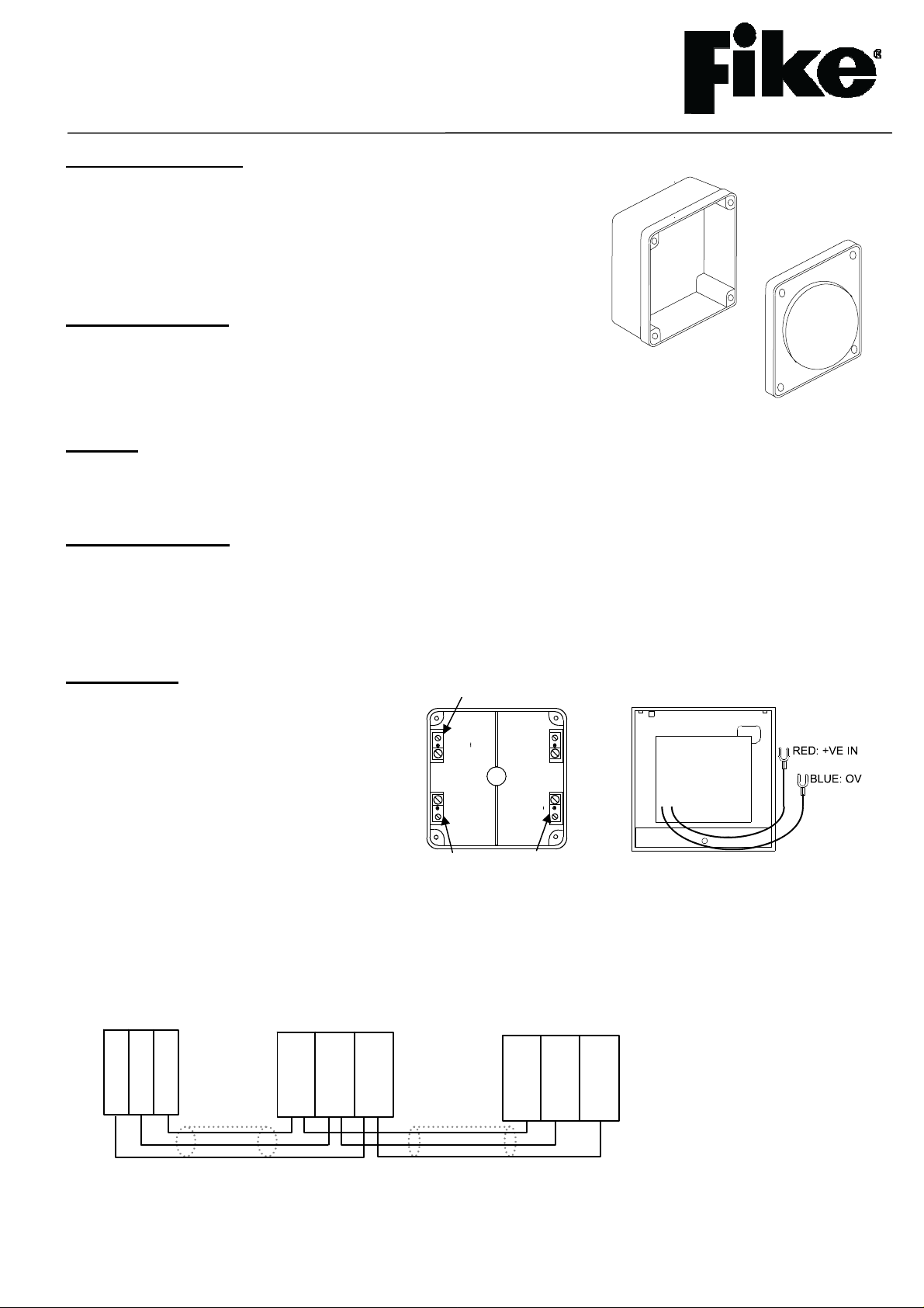
Connections
The cabling used should be 2-core 1.5mm
screened/earthed and fire resistant, of an
MICC or FP200 equivalent type and is to be in
the form of a 2-core radial circuit terminating at
the End of Line device. Cables may be
terminated into the connectors mounted in the
back box, as shown below. Also please ensure
that you use suitable cable glands for cable
entry in order to maintain the IP rating.
Care should be taken when terminating devices to ensure all cables are correctly sleeved and connections are
secure. Improper connections will prevent a system from responding properly in the event of a fire. Please
remember that all high voltage testing must be carried out before the installation of the Flashpoint front unit as this
may cause damage. It is important to maintain the screen continuity in order to protect against data corruption from
interference.
2
CONTROL PANEL
ZONE +VE
ZONE -VE
SCRN
TWINFLEX
FLASHPOINT
ZONE +VE
ZONE -VE
(BLUE)
(RED)
SCREEN
(SCRN)
SCRN
BLUE
RED
TWINFLEX
FLASHPOINT
ZONE +VE
ZONE -VE
(BLUE)
(RED)
(SCRN)
SCREEN
26-0693 Issue 3
Twinflex Flashpoints can be mixed on the same zone as other types of Twinflex device (eg. Twinflex Multipoint
Detectors). The above diagram shows how to make the zone positive, zone negative and screen connections
between the control panel and Twinflex Flashpoints. Refer to the instruction leaflets supplied with other Twinflex
devices for their equivalent wiring/terminal labelling details.
Please note that the SCRN terminal in the Flashpoint back boxes should only be connected to the zone cable
screen and NOT to the building earth. The cable screen is connected to earth at the panel end only, via the zone
“SCRN” terminal (or EARTH terminal on the Twinflex V3 2/4/8 Zone panels).
Once all testing has been carried out on the cabling and ‘continuity & integrity’ has been proven, the Flashpoint unit
may be assembled. The Flashpoint is installed by pushing the front unit gently home. The four fixing screws may
then be tightened as required.
Remember that the device at the end of the line must have its EOL signal activated using the
relevant DIL switch. Do not use a resistor or capacitor (or another manufacturer’s End of Line
device) as the end of line, as this may prevent correct operation of the zone.
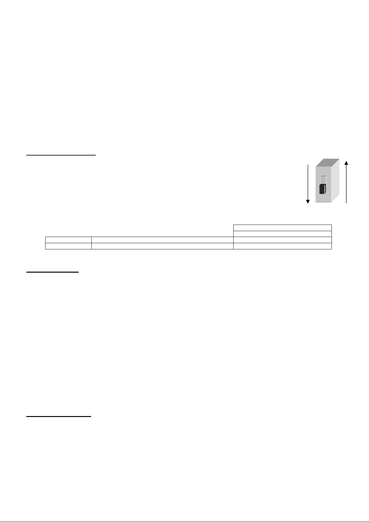
DIL Switch Settings
The device DIL switches may be used to program the operation of the Flashpoint Beacon.
They may be altered whilst the device is still powered or the system may be powered down
completely.
SWITCH ON
The last device on the circuit must have the EOL signal enabled (switch number 1 in the ‘ON’
position).
End of line
Enabled ON
Disabled OFF
DIL SWITCH SETTINGS
1
Technical Data
Dimensions . . . Width . . . 115mm
Height . . . 115mm
Depth . . 70mm
Operating temperature . . . . . . -10
o
C to +50oC.
Voltage Ranges . . . Mains Powered. . . 25.5 to 35V DC
Battery Powered . 20 to 26V DC
Operating Current . . Quiescent . . 428 uA (Typical)
Beacon . . . 5 mA
LED Operation . . . EOL indication . . 5 second interval
Beacon Operation . . Period . . . 1s
Flash Duration . . 15 ms
Loading Units (SLUs) . . Max per zone . . 27 SLU
Beacon . . 1 SLU
Flammability . . . . . . . UL94-V2
IP Rating . . . . . . . IP52
Part Code . . . . . . . 303 0023
Technical Support
Contact your supplier for technical support on this product.
Due to the complexity and inherent importance of a life risk type system, training on this equipment is essential and
commissioning should only be carried out by competent persons. Fike cannot guarantee the operation of any
equipment unless all documented instructions are complied with, without variation. This unit complies with the EMC
directive.
O N
SWITCH OFF
1
26-0693 Issue 3
 Loading...