

Fike Cheetah Xi, SHP-Pro Purge Application Manual
BECAUSE SO MUCH IS AT STAKE™
Application Guide
Cheetah® Xi and SHP-Pro® Purge Operation
The National Fire Protection Association (NFPA) standards associated with gaseous fire suppression systems (e.g.,
carbon dioxide and clean agent) stipulate that suitable steps and safeguards shall be taken to prevent injury or death
to personnel in areas whose atmospheres will be made hazardous by the discharge or thermal decomposition of the
agent. One of the recommended safeguards includes providing a means for prompt ventilation (purge) of the fire zone
after an event has occurred.
In the past, Fike offered a self-contained purge panel (P/N 10-045) that could be installed to meet this requirement;
however, the purge panel has been discontinued and is no longer available from Fike. This does not mean that Fike’s
releasing systems are no longer able to comply with the purge requirement. It simply means that an alternate method
must be used, as described in this application guide, to accomplish the purge requirement. There are two options that
can be used to perform the purge function with Fike’s suppression panels.
Option 1
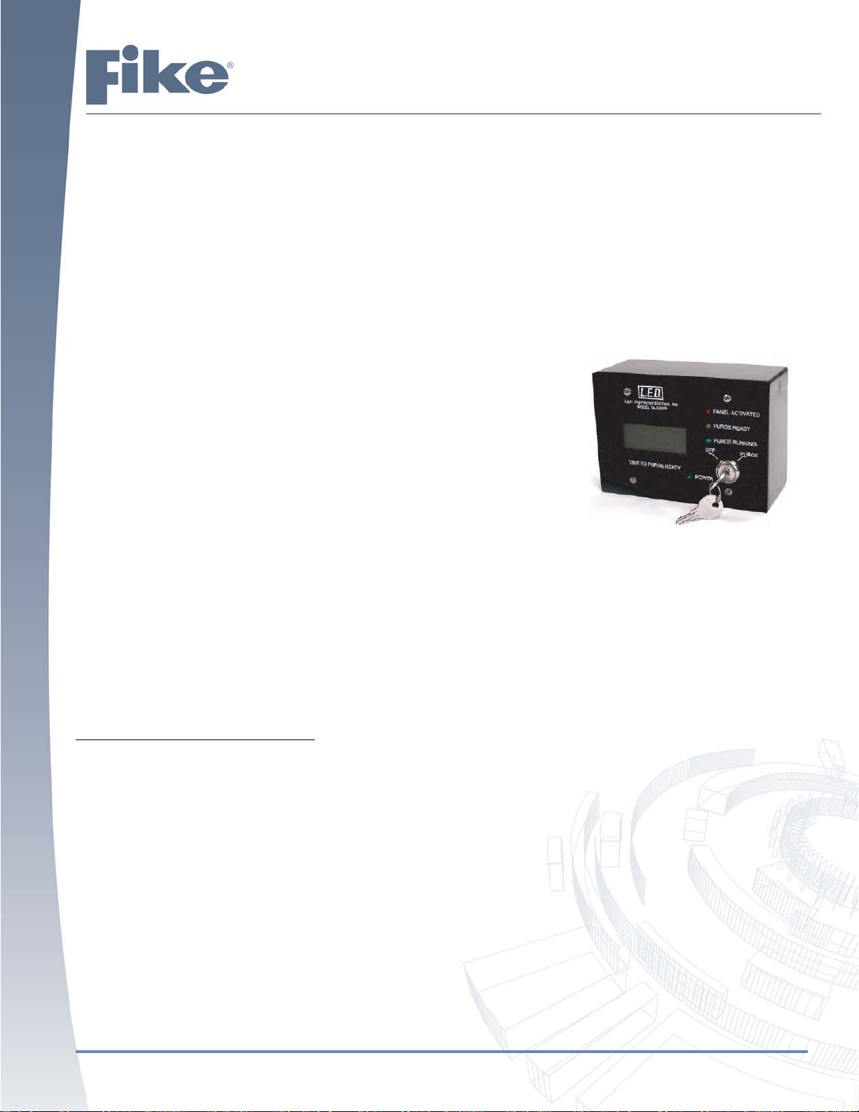
The first option is to purchase and install the Purge Panel Controller, model TA123PP, manufactured by Light Engineered Displays, Inc. (See Figure 1). One
controller must be purchased for each suppression zone and external field
relays must be installed to control the purge components. The L.E.D. purge
controller has been tested by Fike for compatibility and correct operation with
both the Cheetah Xi (including 50 point) and SHP-Pro panels. The purge
controller must be purchased directly from L.E.D. and not from Fike.
Note: This is the only option for performing purge with the SHP-Pro panel.
Option 2
The second option is to utilize the following Cheetah Xi components to accomplish the purge functionality.
2 ea. 55-043 relay module,
1 ea. 55-045 mini-monitor module,
1 ea. 20 Zone annunciator 10-2667,
1 ea. Key-Switch (non-latching capable)*
*The 10-1642 Keyed Abort or 10-2705 Solenoid Disconnect switches can be used for this purpose but would need to
re-label for purge functionality.
General Purge Sequence of Operation
Upon the suppression zone entering into the “Release State”, the following shall occur:
1. A relay module configured for “Release” for the active suppression zone will activate. The relay shall be
configured with a time delay (0 to 80 minutes) for “Purge Soak”.
2. An LED on a twenty-zone annunciator will illuminate to indicate the start of the “Purge Soak” period for the
suppression zone.
3. Upon completion of the “Purge Soak” timer, the relay module’s contacts (item 1) will transfer sending a
“Process” input to the panel via the modules feedback input. This input will be the first interlock required to
initiate purge operation.
Figure 1 - Model TA-123PP
4. An LED on a twenty-zone annunciator will illuminate to indicate the completion of the “Purge Soak” period and
the ready state of the purge system.
5. Upon activation of a purge key-switch (non-latching) configured for the suppression zone, a “Process” input
will be sent to the panel. This input will be the second interlock required to initiate purge operation.
Form No. 06-795, Rev. 0 (02/16)
Page 1 of 8

6. Relay modules assigned to purge operation for the suppression zone will activate and their relay contacts
shall transfer causing the purge system components (i.e., fans, dampers, etc.) for the suppression zone to
activate.
7. Upon activation of the relay modules assigned to purge operation (item 6), the relay module’s contacts will
transfer sending a “Process” input to the panel via the modules feedback input.
8. An LED on a twenty-zone annunciator will illuminate to indicate the active state of the purge system
component.
Panel Programming
The following example shows how to program the Cheetah Xi components to accomplish purge operation. For this
example, the purge operation shall be configured for Zone 1.
The first addressable relay module shall be utilized to initiate the “Purge Soak” period for Zone 1. For this example,
the module shall be assigned to Loop 1, Address 8. The relay module shall be programmed as follows (See Figures 2
and 3).
1. With the Common configuration tab for the relay module selected, assign the device trouble assignment to
Zone 1.
2. In the Miscellaneous Option section, select “Independent Dry Contact” option.
3. Set the State option for the independent dry contact to “Process”.
4. Remaining configuration options, other than the custom message, should be left at default settings.
Figure 2 - Relay Module Configured for “Purge Soak” Period
Page 2 of 8
Form No. 06-795, Rev. 0 (02/16)
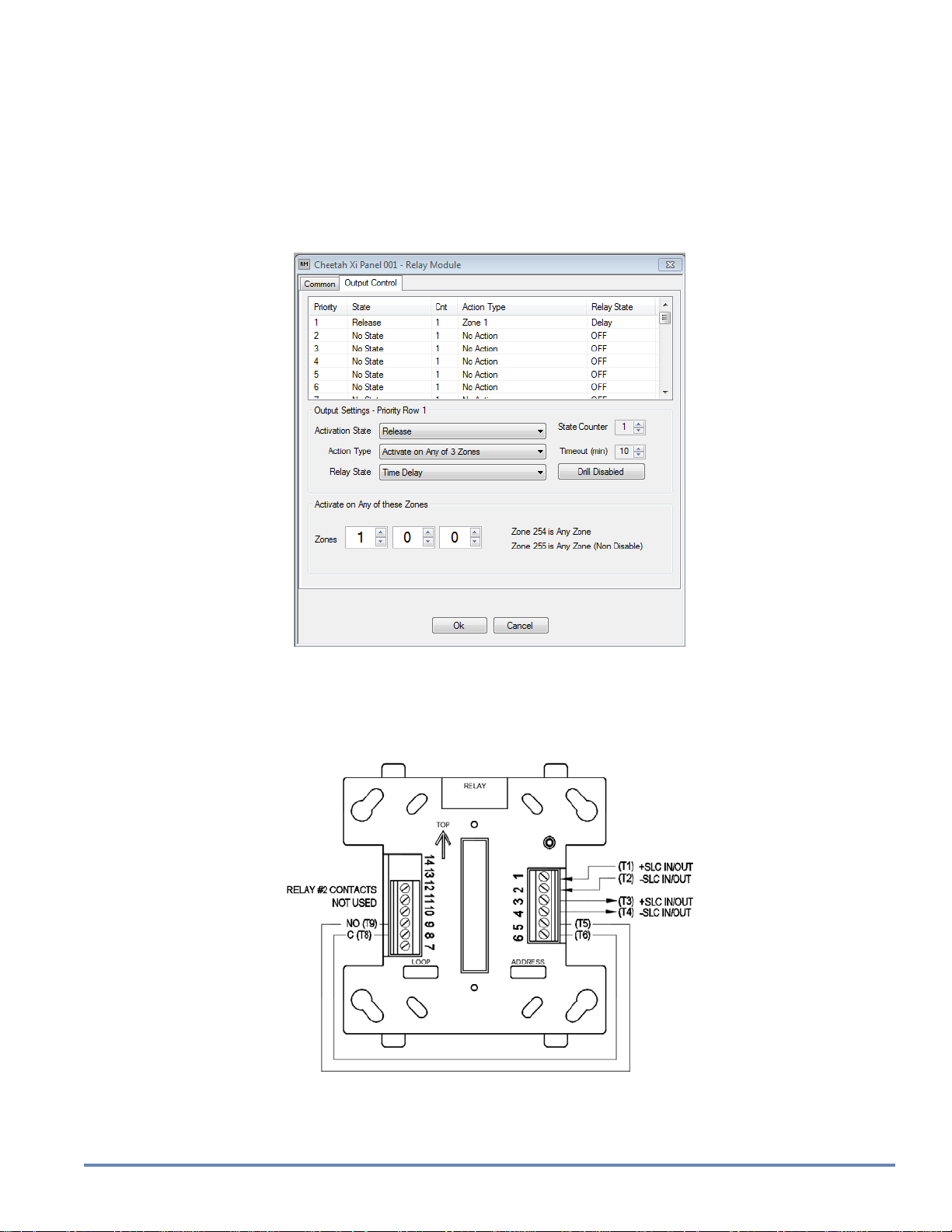
5. Select the Output Control configuration tab (See Figure 3).
6. Set the Activation State option to “Release”.
7. Set the Relay State option to “Time Delay”. A Timeout (min) field will appear. This field will allow you to set
the “Purge Soak” period accordingly. The time can be set in increments of 5 minutes and has a range of 0 to
80 minutes.
8. In the Activate on Any of these Zones fields, set the relay to activate for Zone 1.
9. Remaining configuration options should be left at default settings.
Figure 3 - Relay Module Configured for “Purge Soak” Period
One of the normally open relay contacts on the relay module must be wired to the feedback input on the module as
shown in Figure 4 below. Upon expiration of the relay’s internal timer, the modules relay contacts will transfer causing
activation of the modules feedback input. This will cause a process input for the module (Loop 1, Address 8) to be
received by the Cheetah Xi. This will indicate that the purge system is ready for operation.
Figure 4 - “Purge Soak” Relay Module Wiring
Note: This wiring configuration must be used for each relay used for purge operation.
Form No. 06-795, Rev. 0 (02/16)
Page 3 of 8
 Loading...