

Fike CyberCat 1016, CyberCat 254, CyberCat 50 10-070 Operation & Maintenance Manual
Operation & Maintenance Manual
10-064, CyberCat 1016
10-066, CyberCat 254
Addressable Fire Alarm Control System
P/N 06-326-2, Rev. 6
September 2015

transmit, transcribe, or any part of this manual without express, written
oprietary information intended for distribution to
Installation in accordance with this manual, applicable codes, and the
DEVELOPED BY
COPYRIGHT NOTICE
TRADEMARKS
QUALITY
Fike
704 SW 10
th
Street
P.O. Box 610
Blue Springs, Missouri 64013 U.S.A.
Phone: (800) 979-FIKE (3453)
(816) 229-3405
Fax: (816) 229-0314
Copyright 2016. All rights reserved.
Fike copyrights this m anual and products it describes. You may not reproduc e,
permission from Fike.
This manual contains pr
authorized persons or companies for the sole purpose of conducting business
with Fike. If you distribute any information contained in this manual to
unauthorized persons, you have violated all distributor agreements and we may
take legal action.
Fike is a registered trademark of Fike.
CyberCat
is a registered trademark of Fike.
Fike has maintained ISO 9001 certification since 1996. Prior to shipment, we
thoroughly test our pr oduc ts and r ev iew our d ocum entatio n to as sure t he hig hest
quality in all respects.
WARRANTY
Fike provides a one-year limited manufacturer’s warranty on this product. All
warranty returns m ust be returned from an authorized Fike Distributor . Contact
Fike’s Marketing department for further warranty information.
Fike maintains a repair department that is avail able to repair and return ex isting
electronic components or exchange/purchase previously repaired inventory
component (advance repla cem ent). All returns m ust be a ppro ved pri or to r eturn.
A Material Return Author ization (MRA) number must be indicated on the box of
the item being returned. Contact the appropriate Regional Sales Manager for
further information regarding product return procedures.
LIMITATIONS OF LIABILITY
instructions of the Authority Having Jurisdiction is mandatory. Fike cannot be
held liable for any incident al or consequential damages arising f rom the loss of
property or other damages or losses resulting from the use or misuse of Fike
products beyond the c ost of repair or replac ement of a ny defective com ponents.
Fike reserves the right to make product improvements and change product
specifications at any time.
While every precaution ha s been taken during the preparatio n of this manual to
ensure the accurac y of its content, Fike assumes no respons ibility for errors or
omissions.

TABLE OF CONTENTS
TABLE OF CONTENTS
SECTION DESCRIPTION PAGE
1.0 Introduction .................................................................................................................... 1-1
1.1 About This Manual ........................................................................................................... 1-1
1.2 Product Support ............................................................................................................... 1-1
1.3 Safety Information ........................................................................................................... 1-1
1.4 Related Documentation ................................................................................................... 1-1
1.5 Understanding CyberCat ................................................................................................. 1-2
1.5.1 System Controller ............................................................................................................ 1-2
1.5.2 Intelligent Addressable Devices ...................................................................................... 1-2
1.5.3 Peripheral Devices .......................................................................................................... 1-2
1.5.4 Emergency Communication System ............................................................................... 1-3
1.6 UL (90.23) Operational Limitations .................................................................................. 1-4
2.0 User Interface ................................................................................................................. 2-1
2.1 CyberCat Main Display .................................................................................................... 2-1
2.1.1 System Status LEDs ........................................................................................................ 2-2
2.1.2 History Navigation Buttons .............................................................................................. 2-3
2.1.3 Control Buttons ................................................................................................................ 2-3
2.1.4 Navigation and Function Buttons .................................................................................... 2-4
2.1.5 LCD Display ..................................................................................................................... 2-5
2.1.5.1 System Normal Display ................................................................................................... 2-5
2.1.5.2 System Event Display ...................................................................................................... 2-6
2.1.5.3 Top Level Menu ............................................................................................................... 2-7
2.2 Password Protection ........................................................................................................ 2-8
2.2.1 Logging onto the System ................................................................................................. 2-9
2.2.2 Changing the System Administrator Password ............................................................... 2-9
3.0 System Operation .......................................................................................................... 3-1
3.1 General Operation ........................................................................................................... 3-1
3.1.1 AC Trouble Delay ............................................................................................................ 3-1
3.1.2 Daylight Savings .............................................................................................................. 3-1
3.1.3 Silence Inhibit .................................................................................................................. 3-1
3.1.4 Silence Reminder ............................................................................................................ 3-2
3.1.5 State Counters ................................................................................................................. 3-2
3.1.6 Network Operation ........................................................................................................... 3-2
3.1.6.1 IP Network ....................................................................................................................... 3-2
3.1.7 Positive Alarm Sequence ................................................................................................ 3-3
3.1.8 Smoke Control Operation ................................................................................................ 3-3
3.1.9 Emergency Communication System ............................................................................... 3-3
3.1.9.1 Voice System Priorities .................................................................................................... 3-4
3.2 Panel Menu Structure ...................................................................................................... 3-5
3.3 Panel Operation by Event................................................................................................ 3-5
3.3.1 Power-Up Reset .............................................................................................................. 3-5
3.3.2 Normal State .................................................................................................................... 3-6
3.3.3 Alarm/Waterflow State ..................................................................................................... 3-7
3.3.4 Alarm Verification ............................................................................................................ 3-8
3.3.5 Summing Alarm State ...................................................................................................... 3-9
3.3.6 Trouble State ................................................................................................................. 3-10
3.3.7 Supervisory State .......................................................................................................... 3-11
3.3.8 Pre-Alarm State ............................................................................................................. 3-12
3.3.9 Process State ................................................................................................................ 3-13
3.3.10 Zone Disable State ........................................................................................................ 3-14
3.3.11 Drill State ....................................................................................................................... 3-15
3.3.12 Walk-Test Operation ...................................................................................................... 3-16
UL S2203 CyberCat 254/1016 Operation Manual i
FM P/N: 06-326-2 Rev 6, 09/2015

TABLE OF CONTENTS
SECTION DESCRIPTION PAGE
3.3.13 Fan Restart Operation ................................................................................................... 3-17
3.3.13.1 CRM4 Fan Restart Operation ........................................................................................ 3-17
3.3.13.2 Addressable Relay Fan Restart Operation .................................................................... 3-18
3.3.13.2.1 AHU Fire Key ................................................................................................................. 3-18
3.4 Intelligent Detector Features .......................................................................................... 3-19
3.4.1 Alarm Verification ........................................................................................................... 3-19
3.4.2 Pre-Alarm ....................................................................................................................... 3-19
3.4.3 Acclimate ........................................................................................................................ 3-20
3.4.4 Drift Compensation ........................................................................................................ 3-20
3.4.5 Day/Night/Holida y Settings ............................................................................................ 3-20
3.4.6 Flame Enhance .............................................................................................................. 3-20
3.4.7 Summing ........................................................................................................................ 3-21
3.4.8 Smolder .......................................................................................................................... 3-21
3.4.9 Walk-Test ....................................................................................................................... 3-21
4.0 System History ............................................................................................................... 4-1
4.1 Overview .......................................................................................................................... 4-1
4.2 Viewing History ................................................................................................................ 4-1
4.2.1 Alarm History .................................................................................................................... 4-3
4.2.2 Supervisory History .......................................................................................................... 4-3
4.2.3 Trouble History ................................................................................................................. 4-4
4.2.4 Events History .................................................................................................................. 4-4
4.2.5 Zone History ..................................................................................................................... 4-5
4.2.6 Erase History .................................................................................................................... 4-5
4.2.7 Viewing Additional Event In f ormation .............................................................................. 4-6
5.0 System Diagnostics ....................................................................................................... 5-1
5.1 Overview .......................................................................................................................... 5-1
5.2 Diagnosing Problems ....................................................................................................... 5-1
5.3 Removing or Replacing Panel Components .................................................................... 5-1
5.4 Diagnostic Menu 1 ........................................................................................................... 5-2
5.5.1 Device Diagnostic ............................................................................................................ 5-2
5.5.1.1 Device Type, Location and LED Diagnostics ................................................................... 5-3
5.5.1.2 Device Serial Number Diagnostic .................................................................................... 5-4
5.5.2 Value 1 Diagnostic ........................................................................................................... 5-5
5.5.3 Value 2 Diagnostic ........................................................................................................... 5-6
5.5.4 LED Test .......................................................................................................................... 5-7
5.5.5 CRC (Cyclic Redundanc y Count) .................................................................................... 5-7
5.6 Diagnostic Menu 2 ........................................................................................................... 5-7
5.6.1 Keypad Diagnostics ......................................................................................................... 5-8
5.6.2 VESDA 1 Diagnostics ...................................................................................................... 5-8
5.6.3 VESDA 2 Diagnostics ...................................................................................................... 5-9
5.6.4 Peripheral Diagnostics ..................................................................................................... 5-9
5.6.4.1 Fire-Phone Diagnostics .................................................................................................. 5-10
5.6.5 VESDAnet Communications .......................................................................................... 5-11
5.7 Diagnostic Menu 3 ......................................................................................................... 5-12
5.7.1 Network Diagnostic 1 ..................................................................................................... 5-12
5.7.2 Network Diagnostic 2 ..................................................................................................... 5-13
5.7.3 Network Diagnostic 3 ..................................................................................................... 5-14
5.7.4 Network Reset ................................................................................................................ 5-14
5.7.5 History Diagnostics ........................................................................................................ 5-15
5.7.6 Board Communication Diagnostics ................................................................................ 5-16
ii CyberCat 254/1016 Operation Manual UL S2203
Rev 6, 09/2015 P/N: 06-326-2 FM

TABLE OF CONTENTS
SECTION DESCRIPTION PAGE
5.8 Diagnostic Menu 4 ......................................................................................................... 5-16
5.8.1 Amplifier Status ............................................................................................................. 5-17
5.8.2 Peripheral Supervision Data .......................................................................................... 5-18
5.8.3 Voice Zones ................................................................................................................... 5-21
5.8.3.1 Voice Zones Status ....................................................................................................... 5-22
5.8.3.2 Voice Zones Priorities .................................................................................................... 5-22
5.8.4 Peripheral Firmware Version ......................................................................................... 5-23
5.9 Diagnostic Menu 5 ......................................................................................................... 5-24
5.9.1 Page Status ................................................................................................................... 5-24
5.9.2 Audio Priority Status ...................................................................................................... 5-25
5.9.3 Play Message ID Status ................................................................................................ 5-26
5.9.4 FAAST Detector Status ................................................................................................. 5-27
5.10 Voltages ......................................................................................................................... 5-28
6.0 System Maintenance ..................................................................................................... 6-1
6.1 Overview .......................................................................................................................... 6-1
6.2 Routine Maintenance ....................................................................................................... 6-1
6.3 Fuse Replacement .......................................................................................................... 6-2
6.4 Panel Maintenance Menus .............................................................................................. 6-3
6.4.1 Maintenance Menu 1 ....................................................................................................... 6-3
6.4.1.1 Device Read .................................................................................................................... 6-3
6.4.1.2 Device Address ............................................................................................................... 6-4
6.4.1.3 Device Replace ............................................................................................................... 6-5
6.4.1.4 Walk-Test......................................................................................................................... 6-7
A. Panel Walk-Test .............................................................................................................. 6-8
B. IR Tool Walk-Test ............................................................................................................ 6-9
6.4.1.5 Buzzer .............................................................................................................................. 6-9
6.4.2 Maintenance Menu 2 ..................................................................................................... 6-10
6.4.2.1 Mass Notification System Reset .................................................................................... 6-10
6.4.2.2 Mass Notification System Silence ................................................................................. 6-11
6.4.2.3 Switch Operation ........................................................................................................... 6-11
6.4.2.4 Device Configuration Read............................................................................................ 6-12
6.4.2.5 FAAST ........................................................................................................................... 6-13
6.4.2.6 AHU On ......................................................................................................................... 6-13
Appendix A
A.1 CyberCat Menu Structure (V7.00) ................................................................................... A-1
UL S2203 CyberCat 254/1016 Operation Manual iii
FM P/N: 06-326-2 Rev 6, 09/2015

TABLE OF CONTENTS
LIST OF EXHIBITS
EXHIBIT DESCRIPTION PAGE
1-1 Related Documentati on ................................................................................................... 1-1
1-2 thru 1-41 Programming Features .................................................................................... 1-4 thru 1-43
2-1 CyberCat Main Display .................................................................................................... 2-1
2-2 Status LEDs ..................................................................................................................... 2-2
2-3 Status LED Descriptions .................................................................................................. 2-2
2-4 System Normal Display .................................................................................................... 2-5
2-5 System Event Display ...................................................................................................... 2-6
2-6 Panel-Loop-Address Display ........................................................................................... 2-6
2-7 Expanded Custom Message Display ............................................................................... 2-6
2-8 Top Level Menu ............................................................................................................... 2-7
2-9 Password Access Levels ................................................................................................. 2-8
2-10 Password Entry Screen ................................................................................................... 2-9
2-11 Password Entry Screen ................................................................................................... 2-9
3-1 Record New Device Display ............................................................................................ 3-5
3-2 Power-Up Reset Display .................................................................................................. 3-6
3-3 System Normal Display .................................................................................................... 3-6
3-4 Alarm Display ................................................................................................................... 3-7
3-5 Alarm Verification Display ................................................................................................ 3-8
3-6 Summing Alarm Display ................................................................................................... 3-9
3-7 Trouble Display .............................................................................................................. 3-10
3-8 Supervisory Display ....................................................................................................... 3-11
3-9 Pre-Alarm Display .......................................................................................................... 3-12
3-10 Process Display ............................................................................................................. 3-13
3-11 Zone Disable Display ..................................................................................................... 3-14
3-12 Drill Display .................................................................................................................... 3-15
3-13 Walk-Test Display .......................................................................................................... 3-16
3-14 Automatic Fan Restart Display ...................................................................................... 3-17
3-15 Manual Fan Restart Display ........................................................................................... 3-18
3-16 Detector Programming Features .................................................................................... 3-19
4-1 Current Events Screen ..................................................................................................... 4-1
4-2 Old Events Screen ........................................................................................................... 4-1
4-3 Top Level Menu ............................................................................................................... 4-2
4-4 History Menu .................................................................................................................... 4-2
4-5 Alarm History Screen ....................................................................................................... 4-3
4-6 Supervisory History Screen ............................................................................................. 4-3
4-7 Trouble History Screen .................................................................................................... 4-4
4-8 Events History Screen...................................................................................................... 4-4
4-9 3,200 Events History Screen ........................................................................................... 4-4
4-10 Zone History Screen ........................................................................................................ 4-5
4-11 Erase History Screen ....................................................................................................... 4-5
4-12 Erase History Status ........................................................................................................ 4-5
4-13 Additional Information Screen .......................................................................................... 4-6
4-14 Custom Message Screen ................................................................................................. 4-6
5-1 Diagnostic Menu 1 ........................................................................................................... 5-2
5-2 Device Diagnostic Menu .................................................................................................. 5-2
5-3 Device Type Diagnostic Screen ....................................................................................... 5-3
5-4 Device S/N Diagnostic Screen ......................................................................................... 5-4
5-5 Value 1 Diagnostic Screen ............................................................................................... 5-5
5-6 Value 2 Diagnostic Screen ............................................................................................... 5-6
5-7 LED Test Screen .............................................................................................................. 5-7
5-8 CRC Diagnostic Screen ................................................................................................... 5-7
5-9 Diagnostic Menu 2 ........................................................................................................... 5-7
iv CyberCat 254/1016 Operation Manual UL S2203
Rev 6, 09/2015 P/N: 06-326-2 FM

TABLE OF CONTENTS
EXHIBIT DESCRIPTION PAGE
5-10 Keypad Diagnostics Screen ............................................................................................ 5-8
5-11 VESDA 1 Diagnostics Screen ......................................................................................... 5-8
5-12 VESDA 2 Diagnostics Screen ......................................................................................... 5-9
5-13 Peripheral Diagnostics Screen ........................................................................................ 5-9
5-14 Fire-Phone Diagnostics Screen ..................................................................................... 5-10
5-15 System Sensor Loop Diagnostics Screen ..................................................................... 5-10
5-16 Auxiliary Switch Cards Diagnostics Screen ................................................................... 5-11
5-17 VESDAnet Communication Screen ............................................................................... 5-11
5-18 Diagnostic Menu 3 ......................................................................................................... 5-12
5-19 Network Diagnostics 1 Screen ...................................................................................... 5-12
5-20 Network Diagnostics 2 Screen ...................................................................................... 5-13
5-21 Network Diagnostics 3 Screen ...................................................................................... 5-14
5-22 Network Reset Screen ................................................................................................... 5-14
5-23 History Diagnostics Screen ........................................................................................... 5-15
5-24 Board Comm Diagnostic Screen ................................................................................... 5-16
5-25 Diagnostic Menu 4 ......................................................................................................... 5-16
5-26 Amplifier Operation Status Scr een ................................................................................ 5-17
5-27 Peripheral Supervision Data Screen ............................................................................. 5-18
5-28 Voice Zones Screen ...................................................................................................... 5-21
5-29 Voice Zones Status Screen ........................................................................................... 5-22
5-30 Voice Zones Priorities Screen ....................................................................................... 5-22
5-31 Firmware Version Screen .............................................................................................. 5-23
5-32 Diagnostic Menu 5 ......................................................................................................... 5-24
5-33 Page Status Screen ....................................................................................................... 5-24
5-34 Audio Priority Status Screen.......................................................................................... 5-25
5-35 Play Message ID Status Screen .................................................................................... 5-26
5-36 FAAST Detector Selec tio n Scr een ................................................................................ 5-27
5-37 FAAST Detector Status Screen ..................................................................................... 5-27
5-38 Control Board Test Points ............................................................................................. 5-28
6-1 Controller Fuse Locations................................................................................................ 6-2
6-2 SPS Fuse Locations ........................................................................................................ 6-2
6-3 Maintenance Menu .......................................................................................................... 6-3
6-4 Device Read Screen ........................................................................................................ 6-3
6-5 Device Address Screen ................................................................................................... 6-4
6-6 Device Address Process Screen ..................................................................................... 6-4
6-7 Device Address/New Device Screen ............................................................................... 6-5
6-8 Device Address/Change Screen ..................................................................................... 6-5
6-9 Device Replace Menu ..................................................................................................... 6-5
6-10 Retrieving Configuration Sc reen ..................................................................................... 6-6
6-11 Device Replace Screen ................................................................................................... 6-6
6-12 Device Configuration Screen ........................................................................................... 6-6
6-13 Device Replace Success Screen .................................................................................... 6-6
6-14 Walk-Test Mode Screen .................................................................................................. 6-7
6-15 Walk-Test Mode Screen .................................................................................................. 6-7
6-16 Buzzer Screen ................................................................................................................. 6-9
6-17 Maintenance Menu 2 ..................................................................................................... 6-10
6-18 MNS Reset Screen ........................................................................................................ 6-10
6-19 MNS Silence Screen ..................................................................................................... 6-11
6-20 Switch Timeout Screen .................................................................................................. 6-11
6-21 Configuration Read Screen ........................................................................................... 6-12
6-22 System Normal Screen with Configuration Read Active Screen................................... 6-12
6-23 FAAST Screen ............................................................................................................... 6-13
6-24 AHU On Screen ............................................................................................................. 6-13
UL S2203 CyberCat 254/1016 Operation Manual v
FM P/N: 06-326-2 Rev 6, 09/2015
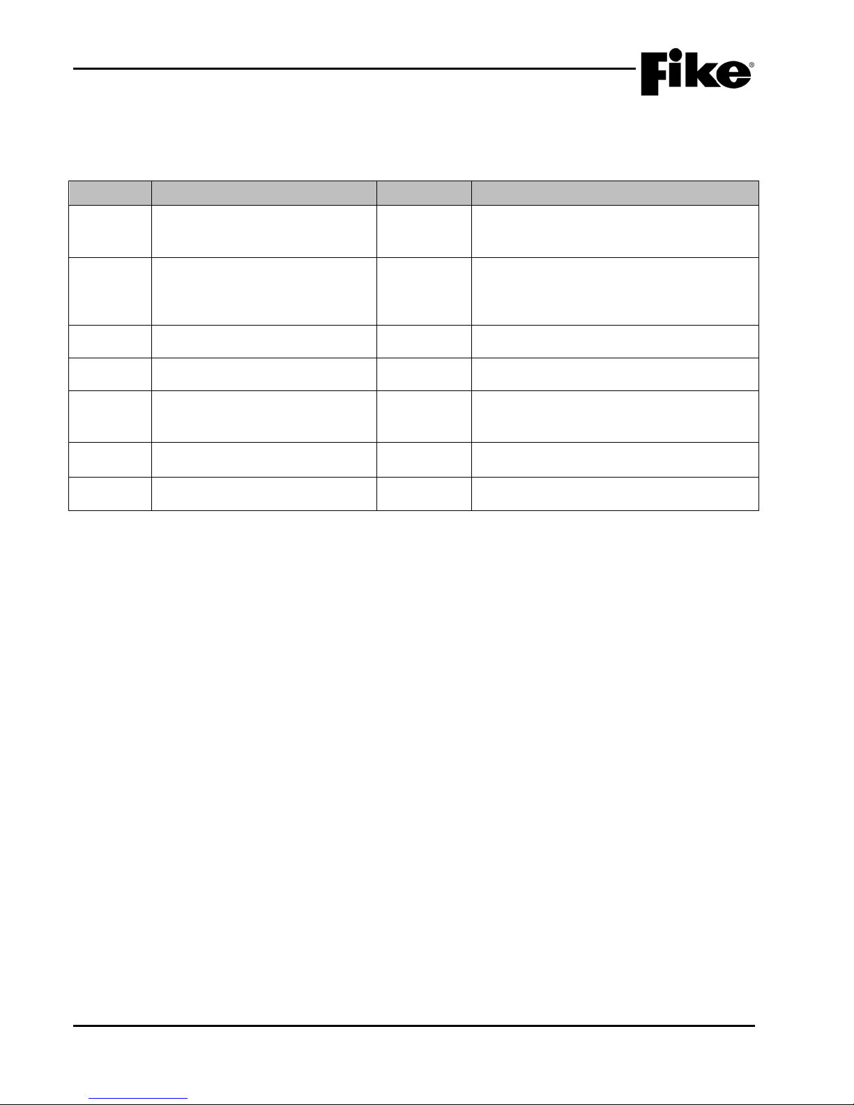
TABLE OF CONTENTS
Manuals
Exhibit 1-4.
Added programming features for AHU
SLC input modules.
Added FAAST XT
aspirating smoke detector
REVISION HISTORY
Document Title: CyberCat Addressable Fire Alarm System Operation and Maintenance Manual
Document Reorder Number: 06-326-2
Revision Section Date Reason for Change
Separated manual into separate
0 All Sections 01/2011
1 Section 1.4 and 1.5 06/2011
2 All Sections 12/2011 Added MNS features
3 Section 1, 3, 5, Appendix A 04/2012 Added FAAST detector and Voice Priorities
Installation, Operation and Programming
Changed CyberCat manual P/N
from 06-326-1 to 06-326 and added
peripheral bus programming feature to
4 Sections 1, 3, 6, and Appendix A 08/2013
restart, audio sync, and MNS activation via
5 All Sections 08/2014
6 All Sections 09/2015 Clarifications and General Updat es
vi CyberCat 254/1016 Operation Manual UL S2203
Rev 6, 09/2015 P/N: 06-326-2 FM

1.0 INTRODUCTION
I
CyberCat Addressable Fire Alarm Control System Installation Manual
06-326
CyberCat Addressable Fire Alarm Control System Programming Manual
06-539
1.1 ABOUT THIS MANUAL
The purpose of this manual is to enable p ersons responsible for the CyberCat system to operate, test and
perform maintenance of the system. It provides a detailed description of how the system operates in
response to different system events and recommended steps for res olution response to each event. Eac h
individual who will be r equired to interface with the panel during a syst em event should thoro ughly read and
understand the instructions contained within this manual.
1.2 PRODUCT SUPPORT
If you have a question or encount er a problem not covered in this m anual, you should first tr y to contact the
distributor that installed th e protection s ystem. Fike has a worldwide distrib ution network . Each distributor is
trained to properly sell , install, and service Fike equip ment. Look on the inside of the door, lef t side, there
should be a sticker with an indication of the distributor who sold the system. If you cannot locate the
distributor, please cal l Fike Customer Service for locating your nearest distribu tor, or go to our web-site at
www.fike.com
the system you can contact Fike Product Support at (800) 979-FIKE (3453) Option 21, Monday through
Friday, 8:00 AM to 4:30 PM CST.
. If you are unable to con tact your ins talling distr ibutor or you simply do n ot know who installed
1.3 SAFETY INFORMATION
Important safety adm onishments ar e used throughout this m anual to warn of possible hazards to persons or
equipment.
a WARNING
Warnings are used to indicate the presence of a hazard
which will or ma y cause personal injury or death, or loss of
service if safet y instructions are not followed or if the hazard
is not avoided.
Caution
Cautions are used to indicate the presence of a hazard
which will or ma y cause damage to the equipm ent if safety
instructions are not followed or if the hazard is not avoided.
Notes: Notes indicate the m essage is important, but is not
of a Warning or C aution category. These notes can be of
great benefit to the user and should be read.
1.4 RELATED DOCUMENTATION
To obtain a complete understanding of the specific features of the CyberCat or to become familiar with related
functions in general, refer to the documentation listed below. Please reference the most current version or
the version noted on the label located on the product.
Exhibit 1-1: Related Documentation
Document Title Part Number
UL S2203 CyberCat 254/1016 Operation Manual 1-1
FM P/N: 06-326-2 Rev 6, 09/2015

1.0 INTRODUCTION
1.5 UNDERSTANDING CYBERCAT
Many Fire Alarm s ystem s today use r elati vely s im ple input and output de vices th at are c onnec ted t o a ce ntral
controller. The central con troller typically polls the input de vices, either one at a time or in groups, and the
individual devices respond with some value. The controller then determines any action needed using the
preprogrammed logic that links the inputs with the appropriate output response.
Unlike the system s described above, the CyberCat is a peer -to-peer system. It utilizes intelligent detectors
and output devices tha t not only include all necessar y processing for decision m aking, but can also include
the control logic for system operation. The logic parameters, along with other device parameters are
downloaded to the devices during system configuration into nonvolatile memory. When an input device
determines that act ion should be taken using its do wnloaded parameters, it transmits a m essage onto the
system’s signaling line circuit (SLC). Output devices receive this message and use their downloaded
parameters to determine if they should take action. This direct communication between devices reduces
response time and reduces the amount of processing that must be performed by the CyberCat controller.
1.5.1 SYSTEM CONTROLLER
Even though the comm and and contr o l proc ess ing for the system is not performed by the CyberCat controller,
it is still an integral par t of the s ystem . Its pr im ary function is t o act as t he comm unicat ion hu b for the de vic es
connected to the systems signaling line circuits (SLC). This provides a path that allows each device to
transmit and receive device status information with one another and the controller. The controller is also
responsible for providing the user interface, performing system timing, delivery of power to field devices,
storing system history events, supervising SLC devices, storing device custom messages, communicating
system events to peripheral devices and providing the system programming interface point.
1.5.2 INTELLIGENT ADDRESSABLE DEVICES
The CyberCat system’s input and output devices are intelligent and maintain their own operating
configuration. The d evices are connected to th e CyberCat control ler’s signaling line circuits (SLC) and use
the SLCs to transmit and rec eive status information with o ne another and the control panel. Each SLC can
contain up to 254 de vices in any com bination. Each devic e must be assigned a unique address (1-254) fo r
proper supervision b y the control ler. W hen shipped f rom F ike, each device is a ddres sed as Loop 0, Address
0. The device address must be c hanged (pr ogrammed) into the device duri ng system installation using the I R
Tool (P/N 55-051) or Ha nd-Held Pr ogramm er (P/N 10-2648) . The panel can also auto-addres s a new de vice
(default loop 0, address 0) when wired to the loop and the Auto Address function is turned ON. It will
recognize the new device by record in g a DEV IC E NOT IN CONFIG trouble and automatically address it to the
first available empty address on the loop (if one exists).
1.5.3 PERIPHERAL DEVICES
The CyberCat system ’s RS485 perip heral bus pro vides an interfac e point that al lows you to c onnect u p to 31
optional peripheral d evices to the s ystem. These de vices are used pro vide remote annu nciation and contr ol
of system events an d to expand the s ystem operat ional cap abilities. I n a net work system, the peri pheral bus
allows all panels to report to a s ingle graphic panel for annunc iation purposes. The per ipheral bus transm its
both zone and panel status information. The same information is transm itted out the panels RS232 bus as
well.
1-2 CyberCat 254/1016 Operation Manual UL S2203
Rev 6, 09/2015 P/N: 06-326-2 FM

1.0 INTRODUCTION
1.5.4 EMERGENCY COMMUNICATION SYSTEM
Fike’s Emergency Communication System (ECS) is a combination system that consists of a variety of
components that have been designed to be seamlessly integrated into the CyberCat system in order to
provide t he following ECS functions: In-Building Fire Emer gency Voice/Alarm Comm unications (EVACS); InBuilding Mass Notification (MNS); Two-Way Emergency Communication; and Wide-Area Mass Notification
system interface. The primary ECS system components include the FCC Digital Paging Assembly, audio
amplifiers, and Local Operating Consoles (LOC) described belo w.
FIRE COMMAND CENTER (FCC) DIGITAL PAGING ASSEMBLY
The FCC Digital P ag ing As s em bl y (P/N 10-2751) is the primary aud io c omponent of the f ire c om mand center.
It provides the primar y connection point for the s ystems audio network riser, paging microphone, and firefighters telephone. The as sembly includes the FCC digital paging car d (P/N 10-2727), FCC paging control
card (P/N 10-2741), a nd FCC microphone housing (P/N 1 0-2757). A digital audio network riser (Class A),
originating from the Digital Paging Assembly, connects all system amplifiers and local operating consoles
together. This allows live audio mess ages (Pages) to be broadcast over the audi o network to the system
amplifiers. The page can originate from the fire command center paging microphone or from any local
operating console microphone.
AMPLIFIERS
The Amplifier Assembly (P/N 10-2773) is des igned to feed a single audio zone and provides an integra l 24
Vdc visual notification appliance circuit. The amplifie r card is capable of providing up to 50 watts of audio
output power to connecte d vo ice e vacuatio n speak ers . The am plifier c ard pro vide s four Class B audio outp ut
circuits that are compatible with 25 or 70 Vrms speakers. An optional Class A card (P/N 10-2746) can be
installed where redundant speaker circuit wiring is required. Each amplifier card can s tore up to 16 digitally
recorded voice mess ages , eac h of whic h may be up to 30 seconds long. User -defined custom mess ages c an
be recorded and downloaded to non-volatile mem ory on the amplifier using the contr ol panel’s programm ing
software (C-Linx). The amplifier card con nects to the digital audio network riser allowing d istribution of live
audio messages (Pages).
LOCAL OPERATING CONSOLES
The Local Operating Consoles (P/N 10-2800 and 10-2801) provides remote paging and voice control
capabilities from a location other than th e fir e comm and center (i.e., nurse stations , guard st ations, e tc.) . The
assembly includes the LOC digital pagi ng card (P/N 10-2816), LO C paging control car d (P/N 10-2798), an d
LOC microphone housing ( P/N 10-2813). The digit al paging card connects to th e digital audio network riser
which allows live audio messages (Pages) to be initiated from the LOC microphone.
Refer to Section 3.1.9 for further details.
UL S2203 CyberCat 254/1016 Operation Manual 1-3
FM P/N: 06-326-2 Rev 6, 09/2015

1.0 INTRODUCTION
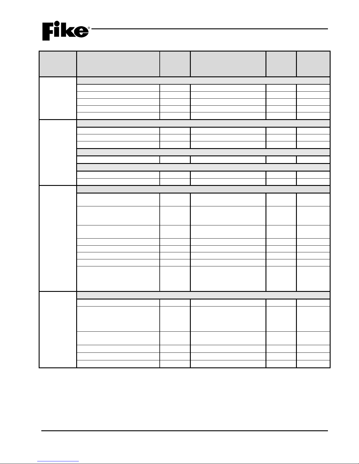
NOTICE TO USERS, INSTALLERS, AUTHORITIES HAVING JURI S DICTION, AND OTHER INVOLVED PARTIES
Fire Alarm Systems, UL 864, certain programming features or options must be limited to specific values or not used at all as indicated below.
Component
Program Feature or Option
Permitted
(Y/N)
(Defaults shown bold)
in UL 864
Notes
Main Board Configuration Options
MISC.
Miscellaneous Options
AC Trouble Delay
Y
0-30 hours, Default 2 hours
1–3
Voice Panel Priorities
• Alarm
Y
1-251, Default 4
4
• Test Alarm
Y
2-252, Default 5
4
• Supervisory
Y
3-253, Default 6
4
• Process
Y
4-254, Default 7
4
Voice City
Y
Standard / Boston / Chicago
/ New York
Standard
5
Voice States on Loop
Y
Enabled / Disabled
6 Fan Restart
Y
Automatic/Manual
Drill/Silence/Acknowledge
N
Enabled / Disabled
Enabled
1,2
Auto Message
Y
Enabled / Disabled
Walktest
Y
Enabled / Disabled
Display Latch of initial event
N
YES/NO
YES
8
Supervision Options
Transformer
Y
120VAC / 240VAC
Loop Style (SLC)
Y
4, 6, or 7 (Class B, A or X)
Ground Fault Level 1
N
Enabled / Disabled
Enabled
2
Ground Fault Level 2
N
Enabled / Disabled
Enabled
2
Main Battery
Y
Supervised / Unsupervised
Auxiliary Battery
Y
Supervised / Unsupervised
3
Auxiliary Loop Module Present
Y
Enabled/ Disabled
3
Auxiliary Power Module Present
Y
Enabled / Disabled
3 Eclipse Device Error is Trouble
Y
Enabled / Disabled
Enabled
7
AHU Restart
Enabled / Disabled
Battery Cutoff
Y
Loop # and Address #
(L: 1-4 Address: 0-254)
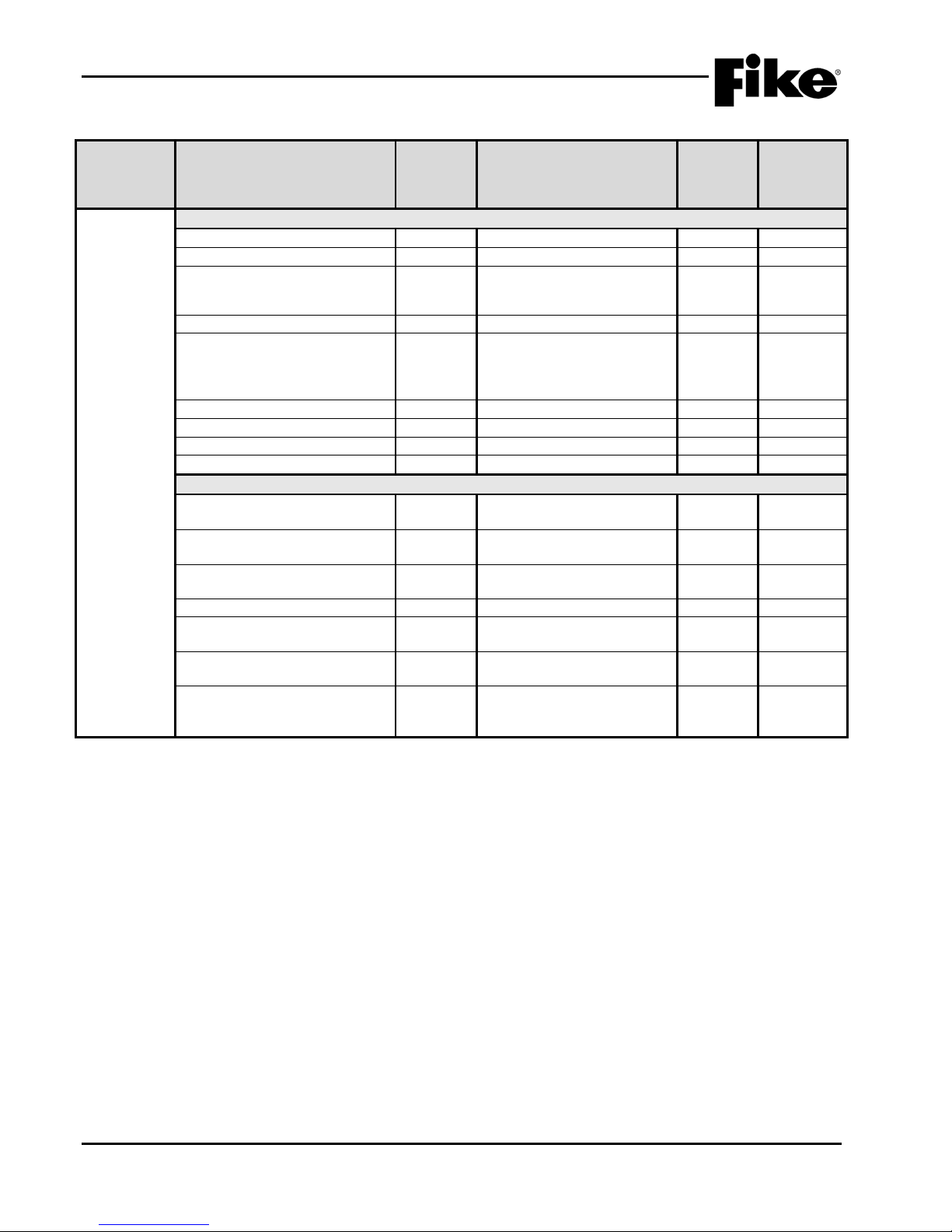
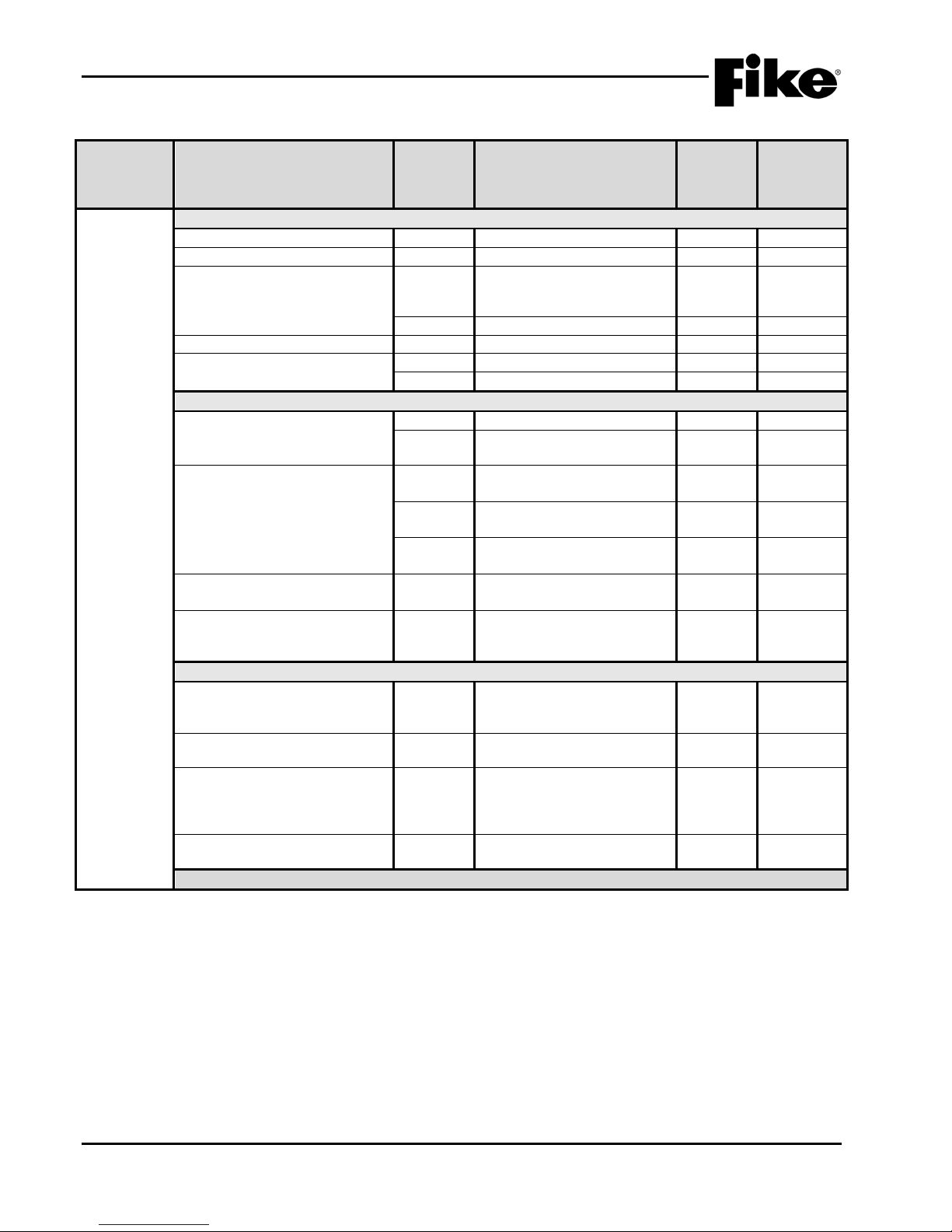
1.6 UL (90.23) OPERATIONAL LIMITATIONS
The following tables ident ify t he co nfigura ble f eatures that ca n be c hang ed b y using t he panel’s progr amm ing
software C-Linx. The tab le also i dentif ies f eatures th at ar e availab le, but are not perm itted to be us ed per the
CyberCat system’s UL listing.
Exhibit 1-2: Programming Features
This product incorporates field-programmable software. In order for the product to comply with the requirements in the Standard for Control Units and Accessories for
Circuit or
in UL
864?
Possible Settings
Settings
permitted
AHU Fire Dept Key Required for
Notes:
1. City of Chicago does not allow use of Drill, Silence and Acknowledge switches.
2. Can only be changed with Facto r y Lev el password.
3. Not used on the CyberCat 254 panel.
4. Voice Panel Priorities allows the user to program a priority scheme for Fire events and MNS events. 0 is used for systems where priority is not
required (0 = None; 1 = Highest and 254 = Lowest).
5. Locality setting is configured for operation of local jurisdiction requirements for Boston, C hicago and New York only. Outside of these
jurisdictions, the setting should be set to Standard.
6. Alert, Evac, Page and MNS Active ma nual activation events are broadcast to the SLC’s to activate or de-activate outputs connected to the SLC.
7. If device on SLC has an internal error the panel produces a trouble state (Yes) and does not just log the event into its history buffer (No). (i.e.
Checksum Error)
8. LCD display to latch on initial Trouble or Supervisory events (YES) or LCD to display current Trouble or Supervisory event (NO)
1-4 CyberCat 254/1016 Operation Manual UL S2203
Rev 6, 09/2015 P/N: 06-326-2 FM
Y
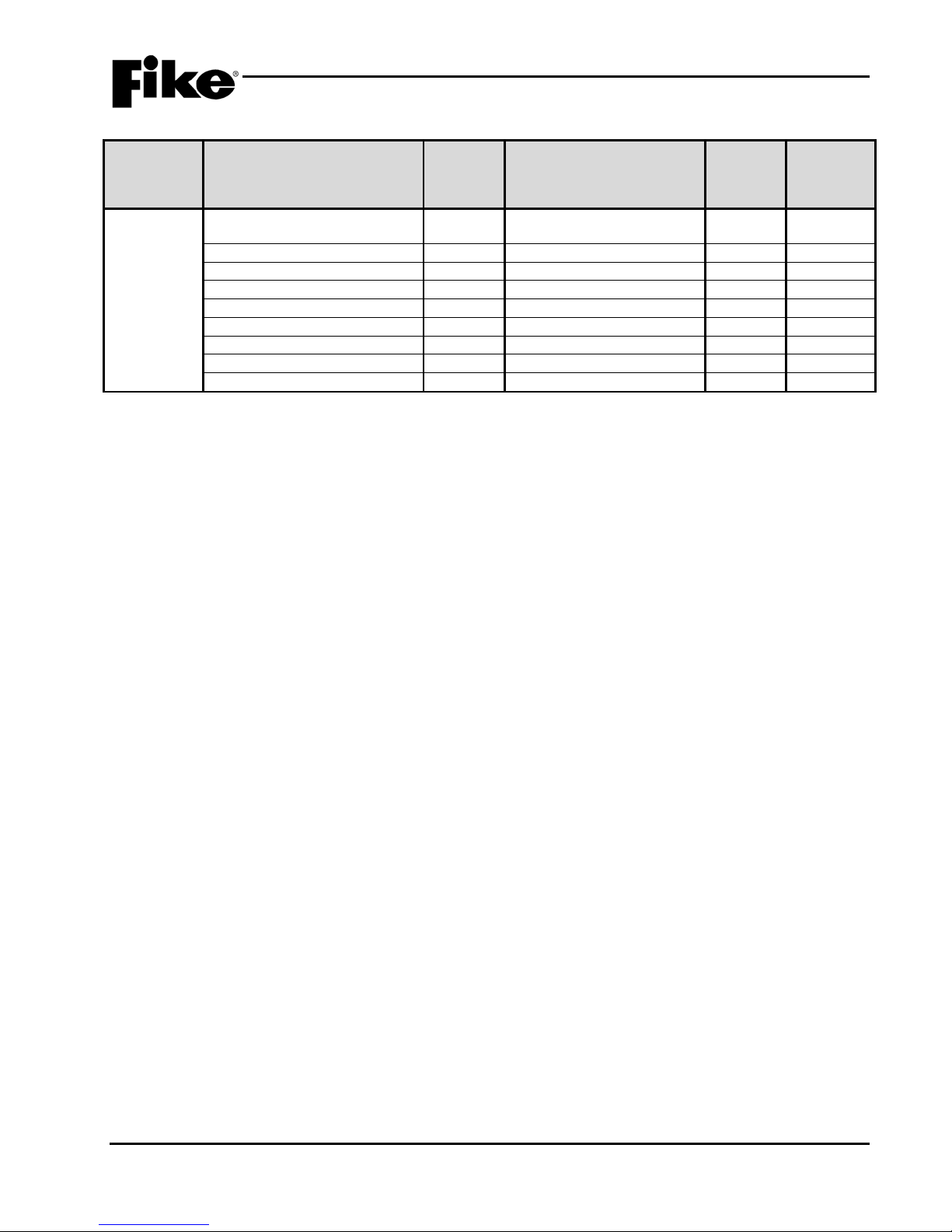
1.0 INTRODUCTION
Component
Program Feature or Option
Permitted
(Y/N)
(Defaults shown bold)
in UL 864
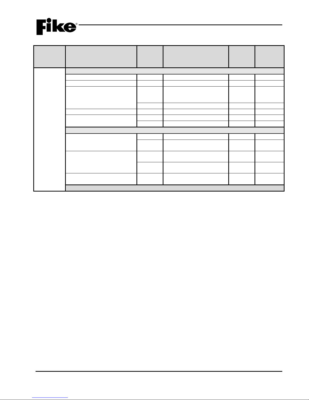
Notes
Silence Options
Unsilence Time
Y
1-24 hours
Silence Reminder
Y
Enabled / Disabled
Silence Inhibit
Y
Enabled / Disabled
Positive Alarm Sequence
Y
Enabled / Disabled
Silence Mode
Y
UL
1
Alarm Sensitivity Changes
Daytime Sensitivities start/stop
Y
12:00 AM – 12:00 AM
Days that use daytime sensitivity
Y
Sunday – Saturday
Use Daylight Savings Time
Y
Enabled / Disabled
Holiday Schedule
Night time sensitivity
Y
20 days total (mm/dd/yyyy)
4
DACT Auto Test
DACT Auto test start hour
Y
0 – 23 (2 default)
DACT Auto test period (hrs.)
Y
0 – 24 (0, 6, 12, 24 hrs.)
NAC
P10 and P11 (NAC 1 & NAC 2)
Sync Protocol
Y
NO / Gentex / System
Sensor /
2,3
State (Activation)
Y
Alarm / Pre-Alarm 1 / PreTrouble / Process
Silenceable
Y
Silenceable / Non
silenceable
Zone Assignment
Y
1 – 254
Circuit
Y
Enabled / Disabled
Drill
Y
Enabled / Disabled
Walktest
Y
Enabled / Disabled
Gentex / System Sensor/
Silence
P2 Main Board Relays
Relay Selection
Y
R1 / R2
5
State (Activation)
Y
Alarm / Pre -Alarm 1 / Pre-
Disable
Silenceable
Y
Non-Silenceable /
Silenceable
Zone Assignment
Y
1 – 254
Circuit
Y
Enabled / Disabled
Drill
Y
Enabled / Disabled
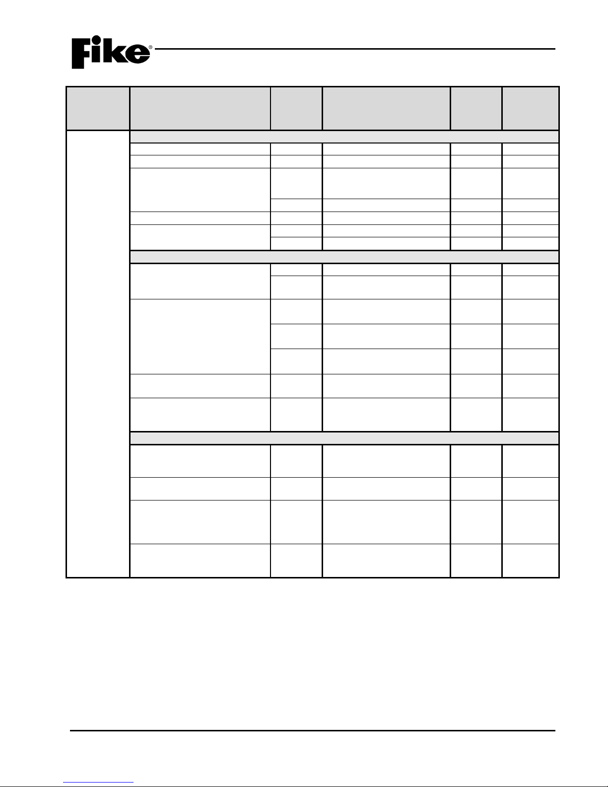
Exhibit 1-3: Programming Features Cont.
Circuit or
MISC.
Time
Functions
in UL
864?
Possible Settings
Alarm 2 / Supervisory /
Settings
permitted
Panel Sync Protocol Y
Relays
Notes:
1. An audible signal that has been silenced at the protected premises shall automatically resound and remain energized until silenced and
retransmitted the signal to any supervising station to which the original signal was transmitted, as applicable, at least once every 24 hours until
the condition is corrected and the product is restored to the normal supervisory condition.
2. If synchronization is selected, both NAC circuits will use the same sync protocol.
3. Refer to Fike document 06-186 for compatible sync protocol.
4. Only allows the installer to assign the night time sensitivity to a different obscuration level than during normal working hours. No other functions
are affected or disable d.
5. Allows on board relays to be configured from the default setting of Alarm for R1 and Supervisory for R2 to the states listed in State (Activation).
UL S2203 CyberCat 254/1016 Operation Manual 1-5
FM P/N: 06-326-2 Rev 6, 09/2015
Gentex – Visual Silence/
System Sensor – Visual
Alarm 2 / Supervisory /
Trouble / Process / Zone

1.0 INTRODUCTION
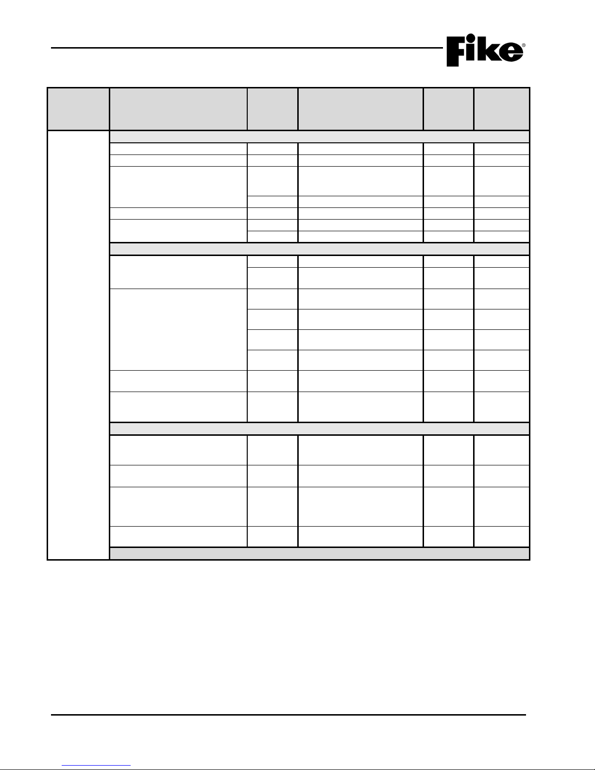
Component
Program Feature or Option
Permitted
(Y/N)
(Defaults shown bold)
in UL 864
Notes
P12
Relay Selection
Y
A / B / C / D
Module
Y
No Module Installed / CRM4 /
2) / Fire Communicator
State
Y
Alarm / Pre -Alarm 1 / Pre-
Disable
Restart Delay
Y
0, 40 – 250 (sec)
Non-Silenceable /
Silenceable
Zone Assignment
Y
1 – 254
Relay
Y
Enabled / Disabled
Drill
Y
Enabled / Disabled
P13
Relay Selection
Y
A / B / C / D
Module
Y
No Module Installed / CRM4 /
2) / Network Interface Card
Alarm / Pre -Alarm 1 / Pre-
Disable
Restart Delay
Y
0, 40 – 250 (sec)
Silenceable
Y
Non-Silenceable /
Silenceable
Zone Assignment
Y
1 – 254
Relay
Y
Enabled / Disabled
Drill
Y
Enabled / Disabled
Zones
Zones
Y
1 – 254
Type
Y
Alarm Zone
Custom Message
Y
20 character user defined
Voice EVAC Mapping
Y
Zones 1 - 254
Voice Alert Mapping
Y
Zones 1 - 254
Zone Enabled
Y
Enabled / Disabled
Zone Chimes
Y
Assign chime code to zone
Exhibit 1-4: Programming Features Cont.
Circuit or
Relays
in UL
864?
Silenceable Y
State Y
Possible Settings
CRPM (Opt 1) / CRPM (Opt
Alarm 2 / Supervisory /
Trouble / Process / Zone
CRPM (Opt 1) / CRPM (Opt
Alarm 2 / Supervisory /
Trouble / Process / Zone
Settings
permitted
1-6 CyberCat 254/1016 Operation Manual UL S2203
Rev 6, 09/2015 P/N: 06-326-2 FM
1.0 INTRODUCTION
Component
Program Feature or Option
Permitted
(Y/N)
(Defaults shown bold)
in UL 864
Notes
(PERIPHERAL ID 02)
Zone Assignment
Y
0 - 254
1
Supervision
Y
Unsupervised / Supervised
1 Voice
Y
No Voice / EVAX / Fike
Status
Y
STD / EXP
2 History Transmit
Y
Compact / Verbose
3
History Packing
Y
Unpacked / Packed
4 History Message
Y
STD / EXP
5
Dual Channel Voice
Y
Enabled / Disabled
Exhibit 1-5: Programming Features Cont.
in UL
Circuit or
864?
Possible Settings
Peripherals Message Y 20 character user defined
Notes:
1. Peripheral device must be added to the Peripherals list before these configuration options are available.
2. This command contains status for Alarm, Supervisory, Trouble and all other states. Peripheral devices that have firmware
version before 3.00 should set this variable to STD, which is the original CyberCat format. The ESP selection refers to an
“Expanded” format. Peripheral devices with 3.00 firmware or newer will used this command. The EXP setting speeds up
operation of the peripheral bus.
3. If set to COMPACT, a message filter within the panel is used to prevent transmission of certain history record events, including
the NEW DEVICE history messages. This is done so that the peripherals do not display messages that are not required. If set
to VERBOSE, a ll history messages are transmitted.
4. HISTORY PACKING refers to how many history records are transmitted back-to-back with minimum time in between. If set to
UNPACKED, history records are sent one at a time. If set to PACKED, up to 50 history records are sent back-to-back. This
will speed up transmission of large amounts of history data.
5. HISTORY MESSAGE refers to what kind of data is packed into the history command. If set to STD (standard), data is packed
as with previous versions. If set to EXP (expanded), both lines 1 and 2 of the history data as shown on the LCD of the panel is
packed into the history command.
Settings
permitted
1
UL S2203 CyberCat 254/1016 Operation Manual 1-7
FM P/N: 06-326-2 Rev 6, 09/2015
1.0 INTRODUCTION
Component
Program Feature or Option
Permitted
(Y/N)
(Defaults shown bold)
in UL 864
Notes
Network Settings
Network Address (Panel ID)
Y
1 - 128
Network Module Type
Y
None / First / Middle / Last
1
Network Panel Message
Y
20 character user defined
where ZZZ = zone number
Network Switch Operation
Y
Global / Local
2
Network Switch IDs
Y
1 – 128
switch commands from.
Network Zones
Y
1 – 254
3
Panel Supervision
Y
1 – 128
4 Wiring Style
Y
Style 4 / Style 7
History
Y
Single / Multiple
Ethernet Settings
000.000.000.000
User Defined
Destination IP Address
Y
000.000.000.000
User Defined
6 Supervision IP Address
Y
000.000.000.000
User Defined
7
Panel IP Supervision
Y
000.000.000.000
4
History Transmits
Y
1 – 10
(Fike recommends 2)
Supervision Timeout
Y
1 – 59 (Sec., Min., Hour)
4 min. default
IP Time Disabled
Send IP Time
Exhibit 1-6: Programming Features Cont.
Circuit or
Network
in UL
864?
Source IP Address Y
Possible Settings
(CUSTOM MSG PANEL 001)
Selects which network
devices the panel will receive
Settings
permitted
5
IP Time Y
8
Accept IP Time
Notes:
1. Defines the location of the panel with respect to others on the network.
2. Defines if the respective panel will react to Reset, Silence, Acknowledge, and Drill commands received from other networked
panels.
3. Defines which network zones will participate in the local panel zone(s).
4. Defines which network panel(s) the selected panel should supervise.
5. Defines the unique Internet Protocol (IP) address for the selected panel.
6. Defines the unique Internet Protocol (IP) address for the panel that is to receive history events from the selected panel.
7. Defines the unique Internet Protocol (IP) address for the panel that is to supervision responses from the selected panel.
8. Used to synchronize panel time over the network.
1-8 CyberCat 254/1016 Operation Manual UL S2203
Rev 6, 09/2015 P/N: 06-326-2 FM
1.0 INTRODUCTION
Component
Program Feature or Option
Permitted
(Y/N)
(Defaults shown bold)
in UL 864
Notes
Common
Loop Number of Device
Y
1 - 4
1 Address of Device
Y
1 – 254
Custom Message
Y
60 character user defined
Loop 1 - Address 001)
Y
Default / User Defined
Zone Assignments
Y
1 – 254
2
Alarm Verification
Y
Time: 0 – 60 seconds
Y
Enabled / Disabled
Sensitivity
Pre-Alarm 1 & 2 Levels
Y
Enabled / Disabled
Y
0.5%/ft. – 4.0%/ft.
(0.1%/ft. increments)
3
Alarm Levels
Y
4
Y
Y
(Warning/Trouble)
Warning 80%/Trouble 100%
Walktest
Y
Walktest at Alarm Level /
1.3%
Device Summing
Broadcast Thresholds for
N
Enabled / Disabled
0.1%/ft. increments)
(%OBS)
(0.5%/ft. increments)
Summing Broadcast State
No
Disabled / Alarm / Summing
Pre-Alarm 1 / Pre-Alarm 2
Summing Addresses
No
1 – 8 (Device addresses to
group)
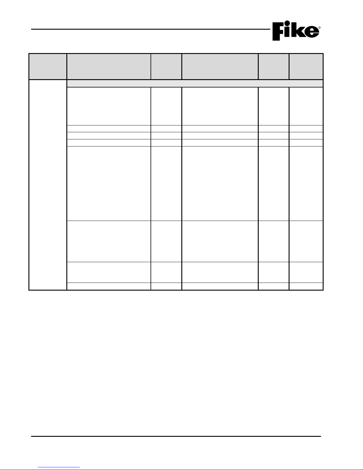
Exhibit 1-7: Programming Features Cont.
Circuit or
Defaults
(Photo
Detector)
Drift Compensation
in UL
864?
(1-001 PHOTO DETECT
Acclimate: 1.3%/ft. – 3.6%/ft.
(High 2.0% - Low 2.5%)
Day/Night: 1.3%/ft. – 3.6%/ft.
(Day 3.6% - Night 3.6%)
Alarm / Supervisory /
Supervisory NL
Y 50 – 100%
Possible Settings
Settings
permitted
5
Walktest with IR / Walktest at
Summing (%OBS)
Summing Activation Level
N 1.0 – 10%/ft.
(8 levels 0.5%/ft. – 4.0%/ft. in
Alarm / Supervisory Latching
/ Supervisory Non-Latch ing /
participate in summing
Notes:
1. CyberCat 254 has only one (1) addressable loop. CyberCat 1016 can have up to four (4) addressable loops.
2. Can be assigned to 4 discrete zones, 2 zone ranges or 1 range and 2 discrete zones.
3. Pre-Alarm 2 setting must always be set equal or higher than Pre-Alarm 1 setting.
4. High setting must be equal or lower obscuration setting than Low setting.
5. Can be set in 1% increments. Trouble must be higher % than Warning.
UL S2203 CyberCat 254/1016 Operation Manual 1-9
FM P/N: 06-326-2 Rev 6, 09/2015
1.0 INTRODUCTION
Component
Program Feature or Option
Permitted
(Y/N)
(Defaults shown bold)
in UL 864
Notes
Remote Annunciator
None / Remote LED –
Sounder Base / Relay Base
Silenceable
Y
Silenceable / Non- Silence
2
Positive Alarm Sequence (PAS)
Y
Disabled / Enabled
2 Output Settings – Priority Row
Y
1 – 8
1
No State / Alarm / Summing
Voice Play Message ID
Action Type
Y
No Action / Activate on
priority rows active
Output Pattern
Y
OFF / ON Continuous /
Walktest / Alert / Action
State Counter
Y
1 – 16
Exhibit 1-8: Programming Features Cont.
Circuit or
Defaults
(Photo
Detector)
in UL
864?
Annunciator Type Y
Activation State Y
Possible Settings
Follows Red / Remote LED –
Follows Green / Remote LED
– Follows Amber / Remote
LED – Independent /
Alarm / Test Alarm / Alarm
Verification ON / Pre-Alarm 1
/ Pre-Alarm 2 / Supervisory /
Trouble / Open Circuit
Trouble / Short Circuit
Trouble / Low Power Trouble
/ Maintenance Trouble /
Process / Zone Disable
Switch / Voice Alert / Voice
Evacuate / Voice Page /
Any of 3 zones / Activate
on All of 3 zones / Activate
on Specific Device /
Activate on multiple
Settings
permitted
1,2
Notes:
1. If annunciator type is set to Independent Operation, Sounder Base, or Relay Base an 8-row priority table will be displayed.
Table values are set using the Output Settings fields.
2. If annunciator type is set to Sounder Base, Silence and Positive Alarm Sequence (PAS) options will be displayed.
1-10 CyberCat 254/1016 Operation Manual UL S2203
Rev 6, 09/2015 P/N: 06-326-2 FM
Slow / Fast / Temporal /
1.0 INTRODUCTION
Component
Program Feature or Option
Permitted
(Y/N)
(Defaults shown bold)
in UL 864
Notes
Common
Loop Number of Device
Y
1 - 4
1 Address of Device
Y
1 – 254
Custom Message
Y
60 character user defined
Loop 1 - Address 001)
Y
Default / User Defined
Zone Assignments
Y
1 – 254
2
Y
Time: 0 – 60 seconds
Y
Enabled / Disabled
Sensitivity
Y
0.5%/ft. – 4.0%/ft.
(0.1%/ft. inc rements)
3
Alarm Levels
Y
(High 2.0% - Low 2.5%)
4 Y
Y
Flame Enhance
N
ON / OFF
Drift Compensation
(Warning/Trouble)
Y
50 – 100%
Warning 80%/Trouble 100%
5
Walktest at Alarm Level /
1.3%
Device Summing
Broadcast Thresholds for
N
Enabled / Disabled
0.1%/ft. increments)
Summing Activation Level
(%OBS)
N
1.0 – 10%/ft.
(0.5%/ft. inc rements)
Summing Broadcast State
N
Disabled / Alarm / Summing
Pre-Alarm 1 / Pre-Alarm 2
Summing Addresses
N
1 – 8 (Device address es to
participate i n summing group)
Remote Annunciator (See Exhibit 1-8 for programming features)
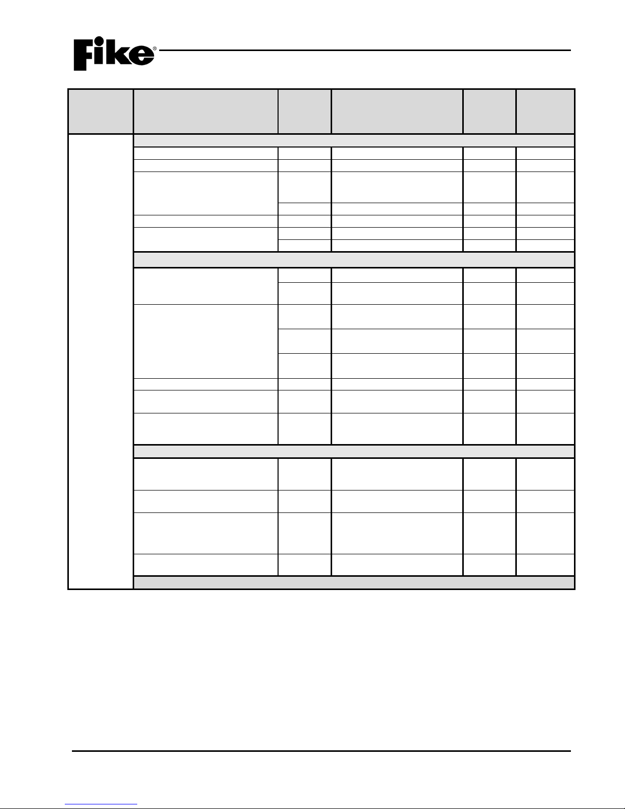
Exhibit 1-9: Programming Features Cont.
Circuit or
Defaults
(Photo/Heat
Detector)
in UL
864?
Alarm Verification
Pre-Alarm 1 & 2 Levels Y
Possible Settings
(1-001 PHO/HT DETECT
Enabled / Disabled
Acclimate: 1.3%/ft. – 3.6%/ft.
Day/Night: 1.3%/ft. – 3.6%/ft.
(Day 3.6% - Night 3. 6%)
Alarm / Supervisory /
Supervisory NL
Settings
permitted
Walktest Y
Walktest with IR / Walktest at
Summing (%OBS)
Notes:
1. CyberCat 254 has only one (1) addressable loop. CyberCat 1016 can have up to four (4) addressable loops.
2. Can be assigned to 4 discrete zones, 2 zone ranges or 1 range and 2 discrete zones.
3. Pre-Alarm 2 setting must always be set equal or higher than Pre-Alarm 1 setting.
4. High setting must be equal or lower obscuration setting than Low setting.
5. Can be set in 1% increments. Trouble must be higher % than Warning.
(8 levels 0.5%/ft. – 4.0%/ft. in
Alarm / Supervisory Latching /
Supervisory Non-Latching /
UL S2203 CyberCat 254/1016 Operation Manual 1-11
FM P/N: 06-326-2 Rev 6, 09/2015
1.0 INTRODUCTION
Component
Program Feature or Option
Permitted
(Y/N)
(Defaults shown bold)
in UL 864
Notes
Common
Loop Number of Device
Y
1 - 4
1 Address of Device
Y
1 – 254
Custom Message
Y
60 character user defined
Loop 1 - Address 001)
Y
Default / User Defined
Zone Assignments
Y
1 – 254
2
Alarm Verification
Y
Time: 0 – 60 seconds
Y
Enabled / Disabled
Sensitivity
Pre-Alarm 1 & 2 Levels
Y
Enabled / Disabled
Y
0.6%/ft. – 4.0%/ft.
(0.1%/ft. increments)
3
Alarm Levels
Y
Acclimate: 0.8%/ft. – 3.4%/ft.
(High 2.0% - Low 2.5%)
4
(Day 1.5% - Night 3.4%)
Y
Alarm / Supervisory /
Supervisory NL
(Warning/Trouble)
Warning 80%/Trouble 100%
Walktest at Alarm Level /
1.3%
Device Summing
Broadcast Thresholds for
N
Enabled / Disabled
0.1%/ft. increments)
(%OBS)
(0.5%/ft. increments)
Summing Broadcast State
N
Disabled / Alarm / Summing
Pre-Alarm 1 / Pre-Alarm 2
participate in summing group)
Remote Annunciator (See Exhibit 1-8 for programming features)
Exhibit 1-10: Programming Features Cont.
Circuit or
Defaults
(Photo/Duct
Detector)
Drift Compensation
in UL
864?
(1-001 DUCT DETECT
Y
Day/Night: 0.8%/ft. – 3.4%/ft.
Y 50 – 100%
Possible Settings
Settings
permitted
5
Walktest Y
Walktest with IR / Walktest at
Summing (%OBS)
Summing Activation Level
N 1.0 – 10%/ft.
(8 levels 0.5%/ft. – 4.0%/ft. in
Alarm / Supervisory Latching
/ Supervisory Non-Latch ing /
Summing Addresses N 1 – 8 (Device addresses to
Notes:
1. CyberCat 254 has only one (1) addressable loop. CyberCat 1016 can have up to four (4) addressable loops.
2. Can be assigned to 4 discrete zones, 2 zone ranges or 1 range and 2 discrete zones.
3. Pre-Alarm 2 setting must always be set equal or higher than Pre-Alarm 1 setting.
4. High setting must be equal or lower obscuration setting than Low setting.
5. Can be set in 1% increments. Trouble must be higher % than Warning.
1-12 CyberCat 254/1016 Operation Manual UL S2203
Rev 6, 09/2015 P/N: 06-326-2 FM
1.0 INTRODUCTION
Component
Program Feature or Option
Permitted
(Y/N)
(Defaults shown bold)
in UL 864
Notes
Common
Loop Number of Device
Y
1 - 4
1 Address of Device
Y
1 – 254
Custom Message
Y
60 character user defined
Loop 1 - Address 001)
Y
Default / User Defined
Zone Assignments
Y
1 – 254
2
Alarm Verification
Y
Time: 0 – 60 seconds
Y
Enabled / Disabled
Sensitivity
Pre-Alarm 1 & 2 Levels
Y
Enabled / Disabled
Y
70°F - 190°F
(5°F increments)
3
Alarm Levels (Day/Night)
Y
Fixed Temp: 135°F - 190°F
(5°F increments)
4 Y
Rate of Rise: 135°F - 174°F
(5°F increments)
4
Walktest
Y
Walktest at 135°F / Walktest
with IR
Remote Annunciator (See Exhibit 1-8 for programming features)
Exhibit 1-11: Programming Features Cont.
in UL
Circuit or
864?
Possible Settings
Defaults
(Heat
Detector)
(1-001 HEAT DETECT
Notes:
1. CyberCat 254 has only one (1) addressable loop. CyberCat 1016 can have up to four (4) addressable loops.
2. Can be assigned to 4 discrete zones, 2 zone ranges or 1 range and 2 discrete zones.
3. Pre-Alarm 2 setting must always be set equal or higher than Pre-Alarm 1 setting.
4. Rate of Rise temperature range is 135°F - 174°F. Fixed temperature range is 135°F - 190°F.
Settings
permitted
UL S2203 CyberCat 254/1016 Operation Manual 1-13
FM P/N: 06-326-2 Rev 6, 09/2015
1.0 INTRODUCTION
Component
Program Feature or Option
Permitted
(Y/N)
(Defaults shown bold)
in UL 864
Notes
Common
Loop Number of Device
Y
1 - 4
1 Address of Device
Y
1 – 254
Custom Message
Y
60 character user defined
Loop 1 - Address 001)
Y
Default/User Defined
Zone Assignments
Y
1 – 254
2
Y
Time: 0 – 60 seconds
Y
Enabled / Disabled
Sensitivity
Pre-Alarm 1 & 2 Levels
Y
Enabled / Disabled
Y
100 – 40 Microns
(5 Micron increm ents)
3
Alarm Levels
Y
Acclimate: 80 – 50 Mi crons
(5 Micron increm ents)
4
Y
Day/Night: 80 – 50 Microns
(5 Micron increm ents)
Y
Alarm / Supervisory /
Supervisory NL
N
Smolder Enhance Off /
Smolder Enhance On
Drift Compensation
Y
50 – 100%
Warning 80%/Trouble 100%
5
Walktest
Y
Walktest at Alarm Level /
1.3%
Device Summing
Broadcast Thresholds for
N
Enabled / Disabled
0.1%/ft. increments)
Summing Activation Level
(%OBS)
N
1.0 – 10%/ft.
(0.5%/ft. inc rements)
Summing Broadcast State
N
Disabled / Alarm/Summing
Pre-Alarm 1 / Pre-Alarm 2
participate in summing group)
Remote Annunciator (See Exhibit 1-8 for programming features)
Exhibit 1-12: Programming Features Cont.
Circuit or
Defaults
(Ion
Detector)
Alarm Verification
in UL
864?
Possible Settings
(1-001 ION DETECT
Settings
permitted
Walktest with IR / Walktest at
Summing (%OBS)
Summing Addresses N
Notes:
1. CyberCat 254 has only one (1) addressable loop. CyberCat 1016 can have up to four (4) addressable loops.
2. Can be assigned to 4 discrete zones, 2 zone ranges or 1 range and 2 discrete zones.
3. Pre-Alarm 2 setting must always be set equal or higher than Pre-Alarm 1 setting.
4. High setting must be equal or lower obscuration setting than Low setting.
5. Can be set in 1% increments. Trouble must be higher % than Warning.
(8 levels 0.5%/ft. – 4.0%/ft. in
Alarm / Supervisory Latching /
Supervisory Non-Latching /
1 – 8 (Device address es to
1-14 CyberCat 254/1016 Operation Manual UL S2203
Rev 6, 09/2015 P/N: 06-326-2 FM

1.0 INTRODUCTION
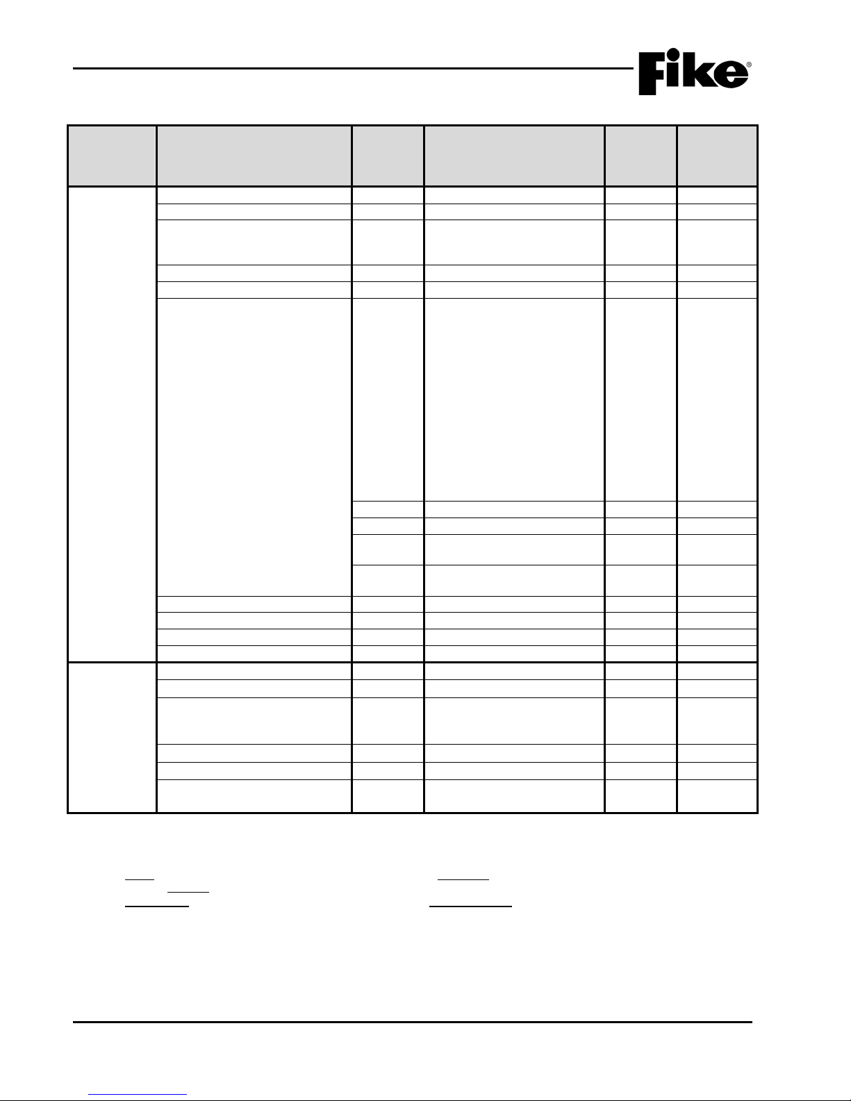
Component
Program Feature or Option
Permitted
(Y/N)
(Defaults shown bold)
in UL 864
Notes
Loop Number of Device
Y
1 - 4
1
Address of Device
Y
1 – 254
Custom Message
Y
60 character user defined
Loop 1 - Address 001)
Y
Default / User Defined
Zone Assignments
Y
1 – 254
2
Message ID
Y
Verify Time: 0 – 255 seconds
3 Y
Latching / Non-Latching
4
Normally Open
Closed
Y
Class B Contact / Class A
Latching
Y
No Short Detection / Short
Detection
Voice/MNS Priority
Y
1 - 255
6, 7
Msg 1 ID
Y
0 - 16
8 Msg 2 ID
Y
0 - 16
8
MNS Timeout
Y
0 - 250
9
Exhibit 1-13: Programming Features Cont.
Circuit or
Defaults
(Monitor
Module)
in UL
864?
Possible Settings
(1-001 INPUT MANALRM
Input Function Type Y No Input Function /
ManAlarm / Detection /
Waterflow / Pre-Alarm 1 /
Pre-Alarm 2 / Supervisory /
Trouble / Process / PAS
Inhibit / Reset / Silence /
Acknowledge / Drill / Zone
Disable / Fan Restart /
Smoke Control Confirmation /
Manual Alarm Stage 2 / AHU
Fire Dept Key / Voice Alert /
Voice Evacuation / Voice
Play Message ID / MNS Play
Y
/ Normally
Settings
permitted
5
Notes:
1. CyberCat 254 has only one (1) addressable loop. CyberCat 1016 can have up to four (4) addressable loops.
2. Can be assigned to 4 discrete zones, 2 zone ranges or 1 range and 2 discrete zones.
3. If monitor module function type is set to Detection, an alarm verification time can be set.
4. Either = PA1, PA2, Supervisory, Trouble, Process, PAS Inhibit; Non-Latch = Reset, Silence, Acknowledge, Zone Disable, Fan
Restart; Latching = ManAlarm, Detection, Waterflow, Drill.
5. NO Contacts = Detection, Manual Alarm, Reset, Supervisory; NO/ NC Conta ct s = Process, Waterflow, PA1, PA2, Trouble, Drill,
Silence, Acknowledge, Zone Disable, PAS Inhibit, Fan Restart.
6. Priority field becomes available only when Input Function is set to a Voice or MNS function.
7. Priority setting cannot be set the same as the panel priority settings for Alarm, Test Alarm, Supervisory, and Process.
8. Message ID field becomes available only when Input Function is set to Voice or MNS Play Message ID.
9. MNS Timeout field becomes available only when input Function is set to MNS Play Message ID.
UL S2203 CyberCat 254/1016 Operation Manual 1-15
FM P/N: 06-326-2 Rev 6, 09/2015
1.0 INTRODUCTION
Component
Program Feature or Option
Permitted
(Y/N)
(Defaults shown bold)
in UL 864
Notes
Loop Number of Device
Y
1 - 4
1
Address of Device
Y
1 – 254
Custom Message
Y
60 character user defined
Loop 1 - Address 001)
Custom Message
Y
Default / User Defined
Zone Assignments
Y
1 – 254
2
Message ID
Y
Verify Time: 0 – 255 seconds
3 Y
Latching / Non-Latching
4
Normally Open
Closed
Y
No Short Detection / Short
Detection
Voice/MNS Priority
Y
1 - 255
6, 7
Msg 1 ID
Y
0 - 16
8
Msg 2 ID
Y
0 - 16
8
MNS Timeout
Y
0 - 250
9
Loop Number of Device
Y
1 - 4
1 Address of Device
Y
1 – 254
Custom Message
Y
60 character user defined
Loop 1 - Address 001)
Custom Message
Y
Default/User Defined
Zone Assignments
Y
1 – 254
2
Input Function
Y
No Input Function / Manual
Alarm
Exhibit 1-14: Programming Features Cont.
Circuit or
Defaults
(Mini Monitor
Module)
in UL
864?
Possible Settings
(1-001 MINI MANALRM
Input Function Type Y No Input Function /
ManAlarm / Detection /
Waterflow /Pre-Alarm 1 / PreAlarm 2 / Supervisory /
Trouble / Process / PAS
Inhibit / Reset / Silence /
Acknowledge / Drill / Zone
Disable / Fan Restart /
Smoke Control Confirmation /
Manual Alarm Stage 2 / AHU
Fire Dept Key / Voice Alert /
Voice Evacuation / Voice
Play Message ID / MNS Play
Y
/ Normally
Settings
permitted
5
Defaults
(Pull Station
Module)
Notes:
1. CyberCat 254 has only one (1) addressable loop. CyberCat 1016 can have up to four (4) addressable loops.
2. Can be assigned to 4 discrete zones, 2 zone ranges or 1 range and 2 discrete zones.
3. If monitor module function type is set to Detection, an alarm verification time can be set.
4. Either = PA1, PA2, Supervisory, Trouble, Process, PAS Inhibit; Non-Latch = Reset, Silence, Acknowledge, Zone Disable, Fan
Restart; Latching = ManAlarm, Detection, Waterflow, Drill.
5. NO Contacts = Detection, Manual Alarm, Reset, Supervisory; NO/NC Contacts = Proc ess, Waterf l ow, PA1, PA2, Trouble, Dril l ,
Silence, Acknowledge, Zone Disable, PAS Inhibit, Fan Restart.
6. Priority field becomes available only when Input Function is set to a Voice or MNS function.
7. Priority setting cannot be set the same as the panel priority settings for Alarm, Test Alarm, Supervisory, and Process.
8. Message ID field becomes available only when Input Function is set to Voice or MNS Play Message ID.
9. MNS Timeout field becomes available only when input Function is set to MNS Play Message ID.
1-16 CyberCat 254/1016 Operation Manual UL S2203
Rev 6, 09/2015 P/N: 06-326-2 FM
(1-001 PULL STATION
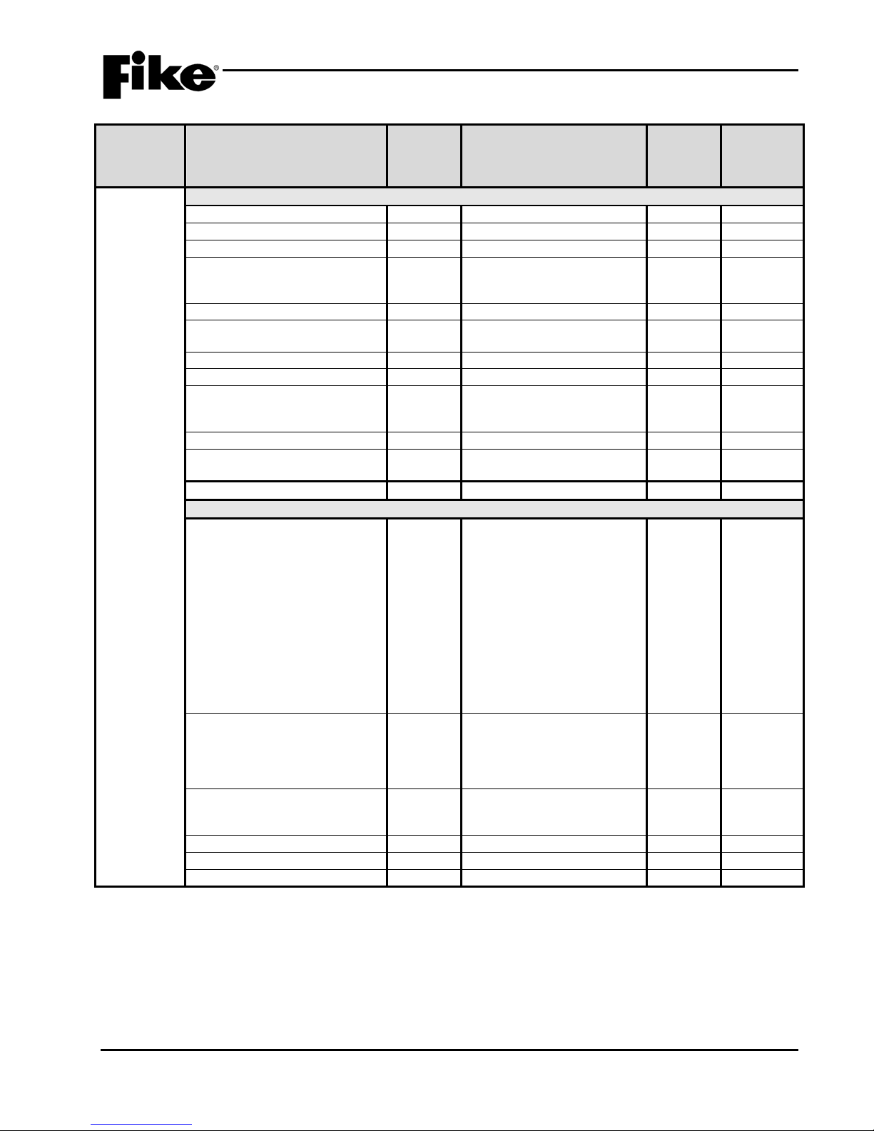
1.0 INTRODUCTION
Component
Program Feature or Option
Permitted
(Y/N)
(Defaults shown bold)
in UL 864
Notes
Common
Loop Number of Device
Y
1 - 4
1 Address of Device
Y
1 – 254
Output
Y
Enabled/Disabled
Custom Message
Y
60 character user defined
Loop 1 - Address 001)
Custom Message
Y
Default/User Defined
Zone Assignments
(device troubles)
Y
1 – 254
2
Defaults for Pre-Action
Y
Yes/No
3 Defaults for 2 Stage Alarm
N
Yes/No
4
Drill Output Pattern
Y
Drill Disabled / On
Temporal
Output Silenceable
Y
Silenceable/Non-Silenceable
Positive Alarm Sequencing
(PAS)
Y
Disabled / Enabled
Power Supply Monitor
Y
Enabled / Disabled
Output Control
Alarm / Summing Alarm /
MNS Message Active
No Action / Activate on Any
priority rows active
Output Pattern
Y
OFF / ON Continuous / Slow
Times / Custom Defined
Output Pattern Set
Y
1 - 3
State Counter
Y
1 – 16
Zone Assignments (activation)
Y
1 - 255
5
Exhibit 1-15: Programming Features Cont.
Circuit or
Defaults
(Supervised
Control
Module)
in UL
864?
Activation State Y
Possible Settings
(1-001 OUTPUT MODULE
Continuous / Slow / Fast /
Test Alarm / Alarm
Verification ON / Pre-Alarm 1
/ Pre-Alarm 2 / Supervisory /
Trouble / Open Circuit
Trouble / Short Circuit
Trouble / Low Power Trouble
/ Maintenance Trouble /
Process / Zone Disable
Switch / Voice Alert / Voice
Evacuate / Voice Page /
Voice Play Message ID /
Settings
permitted
Action Type Y
Notes:
1. CyberCat 254 has only one (1) addressable loop. CyberCat 1016 can have up to four (4) addressabl e loops.
2. Can be assigned to 4 discrete zones, 2 zone ranges or 1 range and 2 discrete zones.
3. Modifies control module configuration for use with Pre-Action solenoid.
4. If selected, the control module configuration will be modified for 2-Stage Alarm Operation (City of Chicago).
5. Can be assigned to any 3 zones, 254 any zone, or 255 any zone (non-disable).
UL S2203 CyberCat 254/1016 Operation Manual 1-17
FM P/N: 06-326-2 Rev 6, 09/2015
of 3 zones / Activate on All of
3 zones / Activate on Specific
Device / Activate on multiple
/ Fast / Temporal / Walktes t /
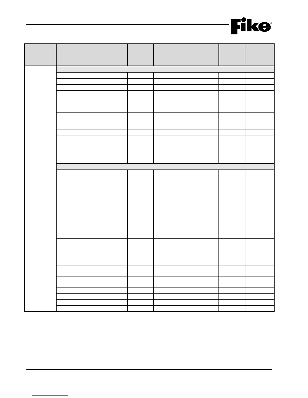
1.0 INTRODUCTION
Component
Program Feature or Option
Permitted
(Y/N)
(Defaults shown bold)
in UL 864
Notes
Common
Loop Number of Device
Y
1 - 4
1 Address of Device
Y
1 – 254
Output
Y
Enabled/Disabled
Custom Message
Y
60 character user defined
Loop 1 - Address 001)
Y
Default/User Defined
Zone Assignments (Device
Troubles)
Y
1 – 253
(4 zones available)
AHU Shutdown Relay
Y
Enabled / Disabled
Restart Delay
Y
0 – 255 seconds
4
Misc. Options
Y
Not Monitored / Monitored
dry contact
5
Positive Alarm Sequencing
(PAS)
Y
Enabled / Disabled
5
Output Control (Note 6)
Activation State
Y
Alarm / Summing Alarm /
MNS Message Active
Action Type
Y
No Action / Activate on Any
priority rows active
Relay State
Y
ON / OFF / Timed / Time
Delay
Timeout
Y
0, 5 – 80 minutes (5 min
increments)
2
State Counter
Y
1 – 16
Output
Y
Silenceable/Non-Silenceable
Drill
Y
Enabled / Disabled
Zone Assignments (activation)
Y
1 - 255
3
Exhibit 1-16: Programming Features Cont.
Circuit or
Defaults
(Relay
Module)
(feedback relay monitoring)
in UL
864?
Possible Settings
(1-001 RELAY MODULE
by dry contact / Independent
Test Alarm / Alarm
Verification ON / Pre-Alarm 1
/ Pre-Alarm 2 / Supervisory /
Trouble / Open Circuit
Trouble / Short Circuit
Trouble / Low Power Trouble
/ Maintenance Trouble /
Process / Zone Disable
Switch / Voice Alert / Voice
Evacuate / Voice Page /
Voice Play Message ID /
Settings
permitted
Notes:
1. CyberCat 254 has only one (1) addressable loop. CyberCat 1016 can have up to four (4) addressable loops.
2. Timeout delay becomes active if relay state is set to ‘Time Delay’.
3. Can be assigned to any 3 zones, 254 any zone, or 255 any zone (non-disable).
4. Restart delay becomes active if relay is configured for AHU shutdown operation.
5. These options are not available if relay is configured for AHU shutdown operation.
6. Output control is disabled if relay is set for AHU Shutdown operation.
1-18 CyberCat 254/1016 Operation Manual UL S2203
Rev 6, 09/2015 P/N: 06-326-2 FM
of 3 zones / Activate on All of
3 zones / Activate on Specific
Device / Activate on multiple
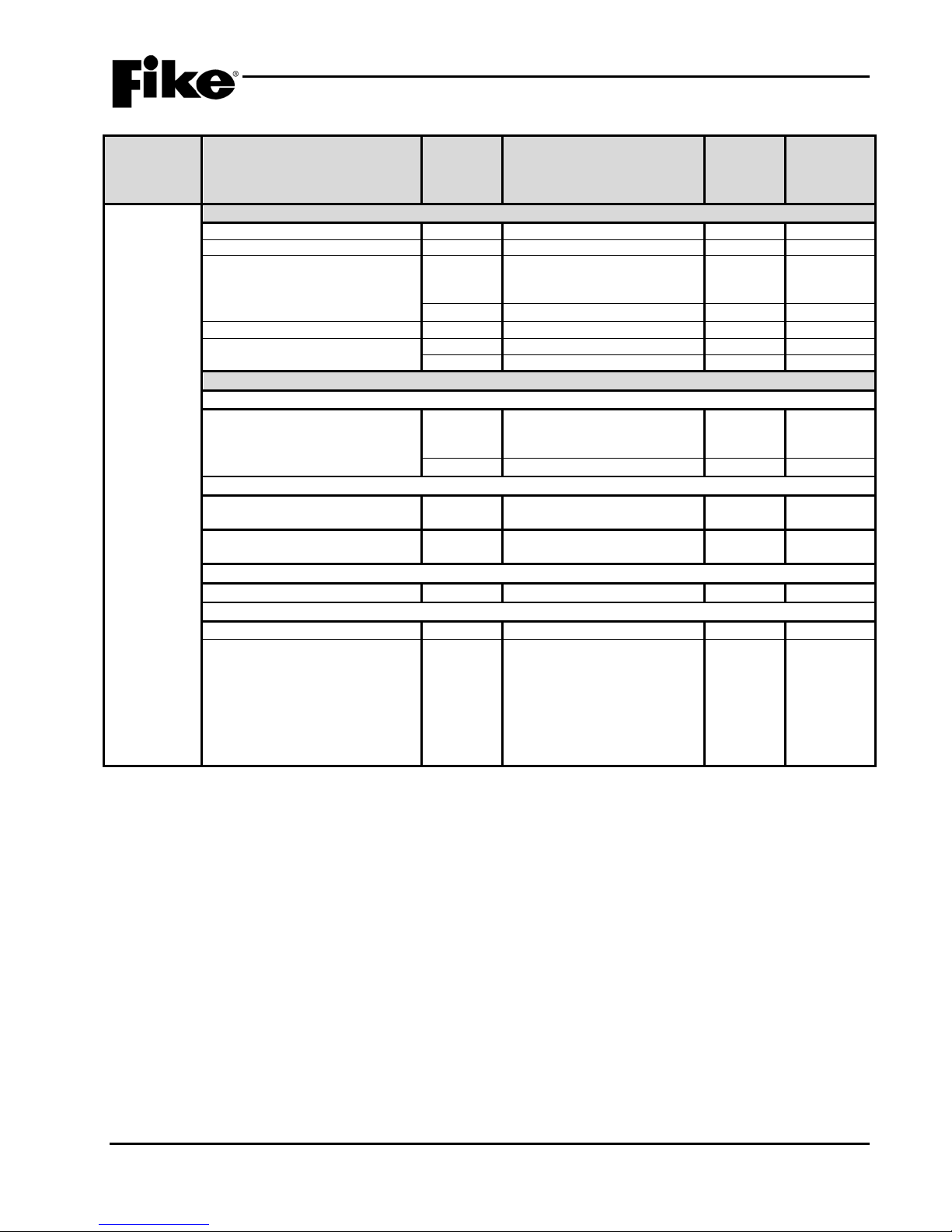
1.0 INTRODUCTION
Component
Program Feature or Option
Permitted
(Y/N)
(Defaults shown bold)
in UL 864
Notes
Common
Loop Number of Device
Y
1 - 4 1
Address of Devic e
Y
1 – 254
Custom Message
Y
60 character user defined
Loop 1 - Address 001)
Y
Default/User Defined
Zone Assignments
Y
1 – 253
2
Walktest
Y
Enabled / Disabled
Y
0.1% - 0.99645% ft. (slider)
States
State Assignment s
Fire 2 / Fire 1 / Acti on 2 / Action 1
Y
Disabled / Alarm / PreAlarm 2 /
Process
3
Y
Latching / Non-Latching
4
Alarm Verification Timers
Fire 2 / Fire 1 / Acti on 2 / Action 1
/ Alert
Y
No Timer / Timer 1 / Timer 2 /
Timer 3
5 Fire 1 or Fire 2 Alarm is Broadcast
when Isolated
Y
Enabled / Disabled
Verificati on Timer Values
Timer 1 / Timer 2 / Timer 3
Y
0 – 255 (seconds)
Acclimate
Acclimate
Y
Disabled / Enabled
Acclimate Hi gh Range
Y
Range 1-H
(1%ft – 3.98818%ft)
6
Exhibit 1-17: Programming Features Cont.
Circuit or
Defaults
(FAAST
Detector)
/ Alert
in UL
864?
Possible Settings
(1-001 FAAST DETECT
PreAlarm 1 / Supervisory /
Settings
permitted
(0.00046%ft – 0.04980%ft)
Range 2-M
(0.05%ft – 0.09982%ft)
Range 3-M
(0.1%ft – 0.99645%ft)
Range 4-L
Notes:
1. CyberCat 254 has only one (1) addressable loop. CyberCat 1016 can have up to four (4) addressable loops.
2. Can be assigned to 4 discrete zones, 2 zone ranges or 1 range and 2 discrete zones.
3. Each detection level on the FAAST det ect or can be mapped to a panel state (user defined).
4. Each detection level can be configured as a latching or non-latching event. Must be latching if configured for Alarm.
5. Each detection level can be configured to initiate one of three Alarm Verification timers.
6. Allows you to set the high sensitivity level for the selected acclimate range.
UL S2203 CyberCat 254/1016 Operation Manual 1-19
FM P/N: 06-326-2 Rev 6, 09/2015
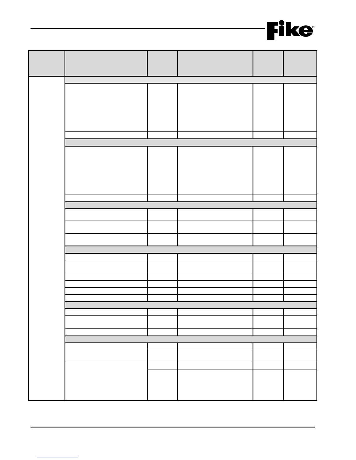
1.0 INTRODUCTION
Component
Program Feature or Option
Permitted
(Y/N)
(Defaults shown bold)
in UL 864
Notes
Day Sensitivity Levels
Fire 1
Y
Range 1-H
(1%ft – 3.98818%ft)
Copy from Night Sensitivity
Y
Yes / No
Night Sensitivity
Fire 1
Y
Range 1-H
(1%ft – 3.98818%ft)
Copy from Day Sensitivity
Y
Yes / No
Miscellaneous
Particulate Level D isplay
Y
Fire 2 / Fire 1 / Action 2 /
Action 1 / Alert
Air Flow Trouble Bou ndary
Y
0 – 100 (% off normal)
(20% default)
Air Flow Trouble Tim er
Y
No Timer / Timer 1 / Timer 2 /
Timer 3
Security
Test Button/Functions Locked
Y
Enabled / Disabled
Isolate Button/ LC D Settings
Locked
Y
Enabled / Disabled
Configuration Locked
Y
Enabled / Disabled
Can be Disabled
Y
Enabled / Disabled
Passcode
Y
0 – 9999 (1111 default)
Device Disable (Isolate Button)
Y
Enabled / Disabled
Reference Detect or
Analog Broadcast Increasing Step
Y
0 - 255
1
Analog Broadcast Decreasing
Step
Y
0 - 255
1
Reference Detect or Address
Y
0 - 254
2 Relays
Configuration (Rel ays 1 – 5)
Y
Latching: Yes / No
Fire 2 / Fire 1 / Action 2 /
Action 1 / Alert
Y
Latching: Yes / No
Y
High Airflow / Low Airflow /
Comm / Time / Sensor
Exhibit 1-18: Programming Features Cont.
Circuit or
Defaults
(FAAST
Detector)
in UL
864?
Possible Settings
(0.00046%ft – 0.04980%ft)
Range 2-M
(0.05%ft – 0.09982%ft)
Range 3-M
(0.1%ft – 0.99645%ft)
Range 4-L, 2.5%
(0.00046%ft – 0.04980%ft)
Range 2-M
(0.05%ft – 0.09982%ft)
Range 3-M
(0.1%ft – 0.99645%ft)
Range 4-L
Settings
permitted
Configuration (Rel ay 6)
Notes:
1. Set to 255 to disable Analog Broadcast.
2. Reference detector cannot use Acclimate feature.
1-20 CyberCat 254/1016 Operation Manual UL S2203
Rev 6, 09/2015 P/N: 06-326-2 FM
Y
Isolate / Filter Minor / Filter
Urgent / Filter Door / Config /
Aspirator / Low Voltage /
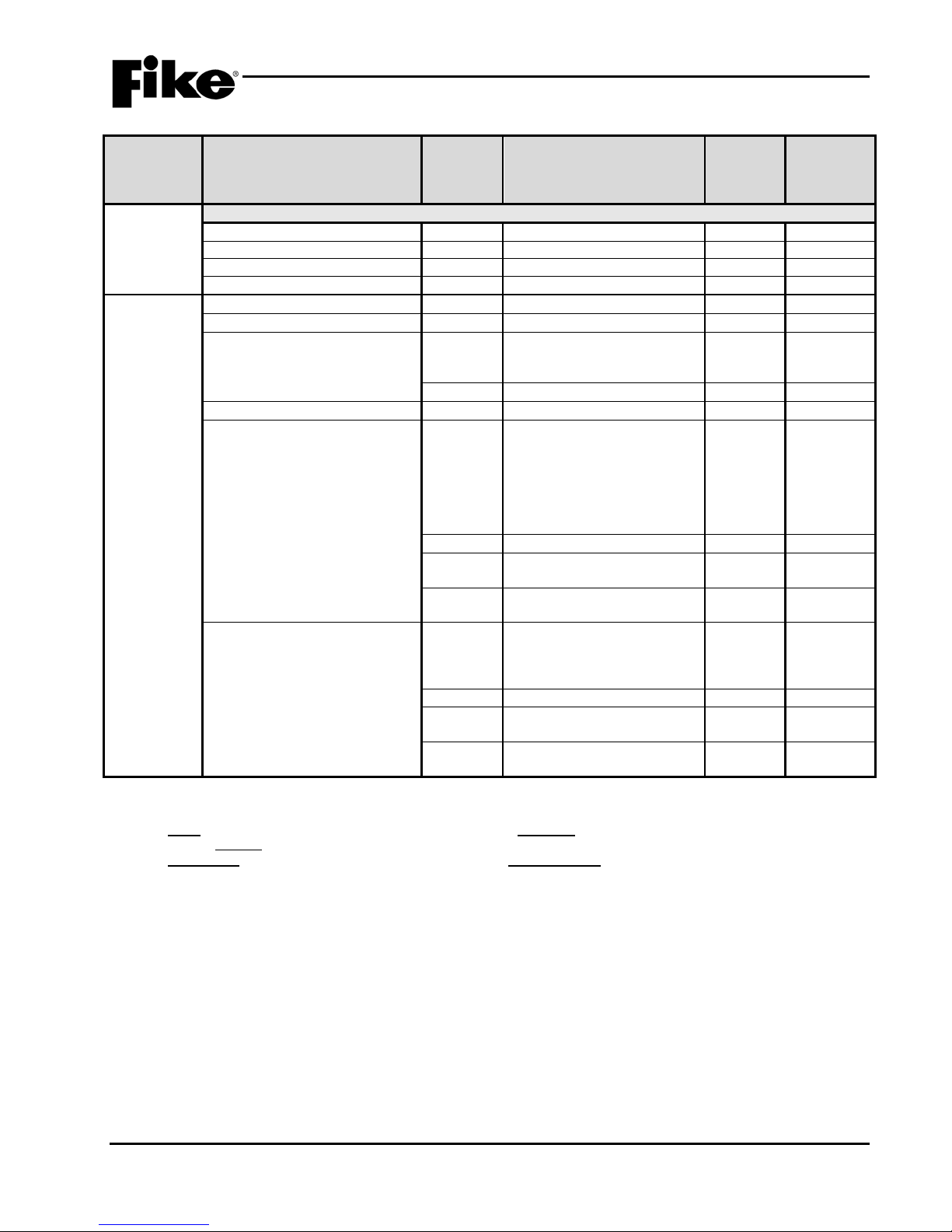
1.0 INTRODUCTION
Component
Program Feature or Option
Permitted
(Y/N)
(Defaults shown bold)
in UL 864
Notes
FAAST XT
Enable Channels
Y
1 - 4
Fan Speed
Y
Slow / Medium / Fast
Alarm Sounder
Y
Off / Pulsed / Continuous
Fault Sounder
Y
Off / Pulsed / Continuous
Defaults
Loop Number of Device
Y
1 - 4
1
Address of Device
Y
1 – 254
Loop 1 - Address 001)
Y
Default / User Defined
Zone Assignments
Y
1 – 254
2
Input 1 Function
Y
No Input Function / Manual
/ Fan Restart
Y
Latching / Non-Latching
3
Y
Normally Open / Normally
Closed
4
Y
Short Detection On / Short
Detection Off
Input 2 Function
Y
No Input Function / Pre-Alarm
Process / AHU FD Key
Y
Latching / Non-Latching
3
Y
Normally Open / Normally
Closed
4 Y
Short Detection On / Short
Detection Off
Exhibit 1-19: Programming Features Cont.
Circuit or
Defaults
(FAAST
Detector)
(Dual
Monitor
Module)
in UL
864?
Possible Settings
Custom Message Y 60 character user defined
(1-001 INPUT ALM/SUP
Alarm / Detection/ Waterflow
/Pre-Alarm 1 / Pre-Alarm 2 /
Supervisory / Trouble /
Process / PAS Inhibit / Reset
/ Silence / Acknowledge / Drill
Settings
permitted
1 / Pre-Alarm 2 /
Supervisory / Trouble /
Notes:
1. CyberCat 254 has only one (1) addressable loop. CyberCat 1016 can have up to four (4) addressable loops.
2. Can be assigned to 4 discrete zones, 2 zone ranges or 1 range and 2 discrete zones.
3. Either = PA1, PA2, Supervisory, Trouble, Process, PAS Inhibit; Non-Latch = Reset, Silence, Acknowledge, Zone Disable, Fan
Restart; Latching = ManAlarm, Detection, Waterflow, Drill.
4. NO Contacts = Detection, Manual Alarm, Reset, Supervisory; NO/NC Contacts = Proc ess, Waterf l ow, PA1, PA2, Trouble, Dril l ,
Silence, Acknowledge, Zone Disable, PAS Inhibit, Fan Restart.
UL S2203 CyberCat 254/1016 Operation Manual 1-21
FM P/N: 06-326-2 Rev 6, 09/2015
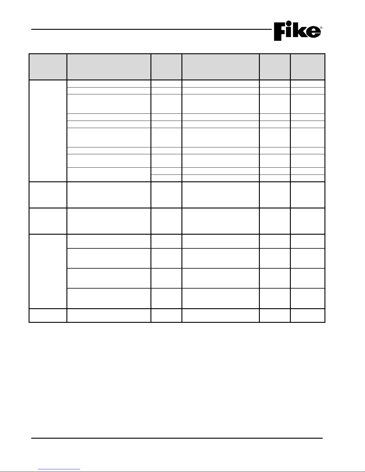
1.0 INTRODUCTION
Component
Program Feature or Option
Permitted
(Y/N)
(Defaults shown bold)
in UL 864
Notes
Loop Number of Device
Y
1 - 4
1
Address of Device
Y
1 – 254
Custom Message
Y
60 character user defined
Loop 1 - Address 001)
Custom Message
Y
Default / User Defined
Zone Assignments
Y
1 – 254
2
Pre-Alarm 2 / Supervisory
Wire Class
Y
Class B / Class A
IDC Power Off Time (seconds)
Y
4 – 64 (8 sec. default)(4 sec
increments)
Alarm Verification
Y
Disabled / Enabled
Y
Time: 0 – 60 seconds
Defaults
Checksum)
Recalculate addressable devi c e
Y
Yes / No
Defaults
Config.)
Reset All Default Device
Y
Yes / No
Line 2 Logo
(Fike Corporation)
Addressable Devices
messages to default)
Y
Yes / No
Peripheral Devices
messages to default)
Y
Yes / No
Air Sampling Devices
messages to default)
Y
Yes / No
(Password)
password (8 available)
Exhibit 1-20: Programming Features Cont.
Circuit or
Defaults
(Conv. Zone
Monitor
Module)
(Update
Device
(Reset
Default
in UL
864?
Possible Settings
(1-001 CONV ZONE MOD
Input Function Y No Input Function /
Detection / Pre-Alarm 1 /
Configuration Checksums?
Configurations?
Settings
permitted
Defaults
Panel LCD Custom Message
Y 20 character user defined
(Custom
Messages
(Restores all device custom
(Restores all device custom
(Restores all device custom
Defaults
Notes:
1. CyberCat 254 has only one (1) addressable loop. CyberCat 1016 can have up to four (4) addressable loops.
2. Can be assigned to 4 discrete zones, 2 zone ranges or 1 range and 2 discrete zones.
Used to assign a unique Level 2
Y 4 digit user defined
1-22 CyberCat 254/1016 Operation Manual UL S2203
Rev 6, 09/2015 P/N: 06-326-2 FM
 Loading...