

Programming Manual
10-064, CyberCat® 1016
®
10-066, CyberCat
Addressable Fire Alarm Control System
254
P/N 06-539, Rev. 3
August 2013

DEVELOPED BY
COPYRIGHT NOTICE
TRADEMARKS
QUALITY
Fike
704 SW 10
th
Street
P.O. Box 610
Blue Springs, Missouri 64013 U.S.A.
Phone: (888) 628-FIKE (3453)
(816) 229-3405
Fax: (866) 211-9239
Copyright © 2011. All rights reserved.
Fike copyrights this manual and pro ducts it describes. You may not reproduce ,
transmit, transcribe, or any part of this manual without express, written
permission from Fike.
This manual contains proprietary information intended for distribution to
authorized persons or companies for the sole purpose of conducting business
with Fike. If you distribute any information contained in this manual to
unauthorized persons, you have violated all distributor agreements and we may
take legal action.
Fike© is a registered trademark of Fike.
CyberCat
®
is a registered trademark of Fike.
Fike has maintained ISO 9001 certification since 1996. Prior to shipment, we
thoroughly test our products and review our documentation to assure the highest
quality in all respects.
WARRANTY
LIMITATIONS OF LIABILITY
Fike provides a one-year limited manufacturer’s warranty on this product. All
warranty returns must be retur ned from an authorized Fike Distribu tor. Contact
Fike’s Marketing department for further warranty information.
Fike maintains a repair department that is available to repair and return existing
electronic components or exchange/purchase previously repaired inventory
component (advance replacement). All returns must be approved prior to return.
A Material Return Authorization (MRA) number must be indicated on the box of
the item being returned. Contact the appropriate Regional Sales Manager for
further information regarding product return procedures.
Installation in accordance with this manual, applicable codes, and the
instructions of the Authority Having Jurisdiction is mandatory. Fike can not be
held liable for any incidental or consequential damages arising from the loss of
property or other damages or losses resulting from the use or misuse of Fike
products beyond the cost of repair or replacement of any defective components.
Fike reserves the right to make product improvements and change product
specifications at any time.
While every precaution has been taken during the preparation of this manual to
ensure the accuracy of its content, Fike assumes no responsibility for errors or
omissions.

TABLE OF CONTENTS
TABLE OF CONTENTS
SECTION DESCRIPTION PAGE
1.0 About This Manual ................................................................................................................ 1-1
1.1 About This Manual .................................................................................................................. 1-1
1.2 Product Support ...................................................................................................................... 1-1
1.3 Safety Information ................................................................................................................... 1-1
1.4 Related Information ................................................................................................................. 1-2
1.5 Revision History ...................................................................................................................... 1-2
2.0 C-Linx Programming Options .............................................................................................. 2-1
2.1 Understanding CyberCat ......................................................................................................... 2-1
2.2 Software Programming Features ............................................................................................ 2-2
3.0 Getting Started ...................................................................................................................... 3-1
3.1 User Interface .......................................................................................................................... 3-1
3.2 Password Protection ............................................................................................................... 3-2
3.2.1 How to Log onto the System ................................................................................................... 3-3
3.2.2 Changing the System Administrator Password ....................................................................... 3-3
3.3 Configuring the System ........................................................................................................... 3-4
3.3.1 Auto-Program .......................................................................................................................... 3-4
3.3.2 Engineered Configure ............................................................................................................. 3-4
3.4 How to Address a Device ........................................................................................................ 3-5
3.4.1 How to Auto Address Field Devices ........................................................................................ 3-5
3.4.2 How to Use the Panel’s Device Address Function .................................................................. 3-6
3.4.3 How to Address Devices with the IR Tool ............................................................................... 3-8
3.4.4 How to Address Devices with the Hand-Held Programmer .................................................. 3-10
3.4.5 How to Address Devices Using C-Linx Device Address Wizard ........................................... 3-12
3.4.6 How to Address Devices Using C-Linx Device Address Function ........................................ 3-13
4.0 Configuration Menu .............................................................................................................. 4-1
4.1 Configuration Menu ................................................................................................................. 4-1
4.2 Configuration Menu 1 .............................................................................................................. 4-1
4.2.1 How to Configure a Field Device ............................................................................................. 4-1
4.2.1.1 How to Change a Devices Alarm Features ............................................................................. 4-2
A. How to Modify a Sensor .............................................................................................. 4-3
B. How to Modify a Control or Relay Module .................................................................. 4-3
C. How to Modify a Monitor Module ................................................................................ 4-7
D. How to Modify a Pull Station ....................................................................................... 4-8
E. How to Delete a Device from the System Configuration ............................................. 4-8
F. How to Read, Write, Enable or Disable a Device ........................................................ 4-9
G. How to Set the AHU Relay Re-start Delay ............................................................... 4-10
4.2.1.2 How to Perform a Configuration Check ................................................................................. 4-11
4.2.2 How to Modify the Panel’s NAC Circuits ............................................................................... 4-11
4.2.2.1 How to Modify NAC Functions .............................................................................................. 4-12
4.2.2.2 How to Set NAC Zone Assignments ..................................................................................... 4-13
4.2.2.3 How to Set NAC Sync Protocol ............................................................................................. 4-14
4.2.3 How to Change SLC Supervision .......................................................................................... 4-14
4.2.3.1 How to Set SLC Command Mode Functions ........................................................................ 4-15
4.2.4 How to Execute the Learn Function ...................................................................................... 4-16
4.2.4.1 Learn New Devices Only ....................................................................................................... 4-17
4.2.4.2 Learn All Devices .................................................................................................................. 4-17
4.2.5 How To Enable Panel Voice Operations ............................................................................... 4-18
4.2.5.1 How To Set Mass Notification Reset Timeout ....................................................................... 4-19
4.2.5.2 How To Set Voice State Priority Levels ................................................................................ 4-19
4.3 Configuration Menu 2 ............................................................................................................ 4-20
4.3.1 How to Set System Time and Date ....................................................................................... 4-20
4.3.2 How to Set System Silencing Options ................................................................................... 4-21
CyberCat 254/1016 Programming Manual i
P/N: 06-539 Rev 3, 08/2013

TABLE OF CONTENTS
SECTION DESCRIPTION PAGE
4.3.3 How to Set System Power Options ....................................................................................... 4-22
4.3.4 How to Modify Daytime Sensitivity Settings .......................................................................... 4-24
4.3.4.1 How to Set Daytime Sensitivity Range ................................................................................. 4-24
4.3.4.2 How to Set Holiday Settings for Daytime Sensitivity ............................................................. 4-25
4.3.5 How to Enable/Disable and Assign Custom Messages to Zones ......................................... 4-25
4.3.5.1 How to Assign a Chime Code to a Zone ............................................................................... 4-26
4.3.5.2 How to Assign Evacuation Sets to a Zone ............................................................................ 4-27
4.4 Configuration Menu 3 ............................................................................................................ 4-28
4.4.1 How to Set Peripheral Device Parameters ........................................................................... 4-28
4.4.1.1 How to Configure Peripheral Devices ................................................................................... 4-29
4.4.1.1.1 Peripheral Device Testing ..................................................................................................... 4-30
4.4.1.1.2 How to Program a 256 LED Graphic .................................................................................... 4-30
4.4.1.1.3 How to Program an Amplifier ................................................................................................ 4-31
4.4.1.1.4 How to Program a Fire-Phone Module ................................................................................. 4-34
4.4.1.2 How to Set the Peripheral Bus Command Source ................................................................ 4-35
4.4.1.3 How to Set the Peripheral Bus Speed .................................................................................. 4-35
4.4.1.4 How to Set the Peripheral Bus Command Set ...................................................................... 4-36
4.4.2 How to Enable/Disable System Walktest .............................................................................. 4-37
4.4.3 How to Enable/Disable System Ground Fault Detection ...................................................... 4-37
4.4.4 How to Enable/Disable Day/Night Sensitivity Feature .......................................................... 4-38
4.5 Configuration Menu 4 ............................................................................................................ 4-38
4.5.1 How to Set AC Trouble Delay ............................................................................................... 4-39
4.5.2 How to Configure VESDA Detectors ..................................................................................... 4-39
4.5.2.1 How to Set VESDA Alarm Features ...................................................................................... 4-40
4.5.2.2 How to Set VESDA Sector/Zone Correlation ........................................................................ 4-41
4.5.2.3 How to Set VESDA Zone Number and Loop/Addr ................................................................ 4-41
4.5.2.4 How to Select VESDA Communication Command Set ......................................................... 4-42
4.5.3 How to Configure Auxiliary Power Circuits as AUX/NACs .................................................... 4-42
4.5.3.1 How to Set an Auxiliary Power Circuit as an AUX/NAC ........................................................ 4-43
4.5.3.2 How to Assign Zones to the AUX/NAC Circuit ...................................................................... 4-44
4.5.4 How to Assign Power Cut-Off Relay Address ....................................................................... 4-45
4.5.5 How to Configure Panel Relays and Optional Modules ........................................................ 4-45
4.5.5.1 How to Set Optional Module Mounting Location ................................................................... 4-46
4.5.5.2 How to Set the Function of the Panel’s On-Board Relays .................................................... 4-47
4.5.5.3 How to Assign Relays to a Zone ........................................................................................... 4-48
4.5.5.4 How to Set Fan Restart Mode ............................................................................................... 4-49
4.6 Configuration Menu 5 ............................................................................................................ 4-49
4.6.1 How to Change System Logo ............................................................................................... 4-50
4.6.2 How to Auto Address Devices .............................................................................................. 4-50
4.6.3 How to Configure Dialer Test ................................................................................................ 4-51
4.6.4 How to Configure Panel Network .......................................................................................... 4-51
4.6.4.1 How to Set Panel’s Network ID ............................................................................................. 4-52
4.6.4.2 How to Configure Network Module ....................................................................................... 4-53
4.6.4.3 How to Assign Panel to Network Zones ................................................................................ 4-54
4.6.4.4 How to Set the Number of History Repeats ............................................................................ 4-5
4.6.4.5 How to Configure Network Switch Functions ........................................................................ 4-55
4.7 Configuration Menu 6 .............................................................................................................. 4-6
4.7.1 How to Set Panel’s IP Addresses ......................................................................................... 4-56
4.7.1.1 How to Clear Monitoring Panel’s IP Addresses .................................................................... 4-56
4.7.2 How to Configure Panel for Network Supervision ................................................................. 4-57
4.7.3 How to Set IP Time Parameters ........................................................................................... 4-58
4.7.4 How to Disable Panel’s Switch Operation ............................................................................. 4-59
4.7.5 How to Set Panel’s LED Operation ....................................................................................... 4-59
4.8 Configuration Menu 7 ............................................................................................................ 4-60
4.8.1 How to Enable AHU Key Requirement Feature .................................................................... 4-60
APPENDIX A CyberCat Menu Structure (V6.XX)
ii CyberCat 254/1016 Programming Manual
Rev 3, 08/2013 P/N: 06-539

TABLE OF CONTENTS
LIST OF EXHIBITS
EXHIBIT DESCRIPTION PAGE
1-1 Related Documentation .................................................................................................................. 1-2
2-1 thru 2-40 C-Linx (V6.XX) Programming Features .......................................................................... 2-2 thru 2-42
3-1 Control Panel Keypad and Display ................................................................................................. 3-1
3-2 Password Access Levels ................................................................................................................ 3-2
3-3 Password Entry Screen .................................................................................................................. 3-3
3-4 Password Entry Screen (Password Change) ................................................................................. 3-3
3-5 Auto Address Screen ..................................................................................................................... 3-5
3-6 Device Address Screen .................................................................................................................. 3-6
3-7 Connect Device Screen .................................................................................................................. 3-6
3-8 New Device Detected Screen ......................................................................................................... 3-7
3-9 Connect Device Screen .................................................................................................................. 3-7
3-10 Address Change Completed Screen .............................................................................................. 3-7
3-11 Address Change Failed Screen ...................................................................................................... 3-7
3-12 IR Communication Screen .............................................................................................................. 3-8
3-13 IR Communication Tool .................................................................................................................. 3-9
3-14 Loop Start Screen ........................................................................................................................ 3-10
3-15 Device Address Screen ................................................................................................................ 3-10
3-16 Connect Device Screen ................................................................................................................ 3-10
3-17 New Device Detected Screen ....................................................................................................... 3-11
3-18 Connect Device Screen ................................................................................................................ 3-11
3-19 Address Change Completed Screen ............................................................................................ 3-11
3-20 Address Change Failed Screen .................................................................................................... 3-11
4-1 Configuration Menu 1 ..................................................................................................................... 4-1
4-2 Device Configuration Menu ............................................................................................................ 4-1
4-3 Alarm Features Screen................................................................................................................... 4-2
4-4 Alarm Features Screen (Sensors and Detectors) ........................................................................... 4-3
4-5 Alarm Features Screen (Control Module) ....................................................................................... 4-3
4-6 Any of 3 Zones Function Screen .................................................................................................... 4-4
4-7 All of 3 Zones Function Screen ...................................................................................................... 4-5
4-8 Select Device Function Screen .............................................................................................
4-9 Row Anding Function Screen ......................................................................................................... 4-6
4-10 Alarm Features Screen (Monitor Module)....................................................................................... 4-7
4-11 Alarm Features Screen (Pull Station Module) ................................................................................ 4-8
4-12 Delete Device Screen ..................................................................................................................... 4-8
4-13 Read/Write/Enable/Disable Screen ................................................................................................ 4-9
4-14 AHU Re-start Delay Screen .......................................................................................................... 4-10
4-15 Configuration Check Screen ......................................................................................................... 4-11
4-16 NAC Configuration Menu.............................................................................................................. 4-11
4-17 NAC Functions Screen ................................................................................................................. 4-12
4-18 NAC Zone Assignment Screen ..................................................................................................... 4-13
4-19 NAC Sync Protocol Screen .......................................................................................................... 4-14
4-20 SLC Configuration Screen ............................................................................................................ 4-14
4-21 SLC Command Mode Screen ....................................................................................................... 4-15
4-22 LEARN Screen ............................................................................................................................. 4-16
4-23 LEARN New Devices Screen ....................................................................................................... 4-16
4-24 LEARN Mode Active Screen ........................................................................................................ 4-16
4-25 LEARN All Devices Screen .......................................................................................................... 4-17
4-26 LEARN Mode Active Screen ........................................................................................................ 4-17
4-27 Voice Operations Screen .............................................................................................................. 4-18
4-28 MNS Reset Screen ....................................................................................................................... 4-19
4-29 Voice States Priority Screen ......................................................................................................... 4-19
4-30 Configuration Menu 2 ................................................................................................................... 4-20
4-31 Time Control Screen .................................................................................................................... 4-20
4-32 Silence Screen ............................................................................................................................. 4-21
4-33 Power Screen (CyberCat 254) ..................................................................................................... 4-22
4-34 Power Screen (CyberCat 1016) ................................................................................................... 4-23
4-35 Daytime Sensitivity Menu ............................................................................................................. 4-24
4-36 Daytime Sensitivity Range Screen ............................................................................................... 4-24
......... 4-6
CyberCat 254/1016 Programming Manual iii
P/N: 06-539 Rev 3, 08/2013

TABLE OF CONTENTS
EXHIBIT DESCRIPTION PAGE
4-37 Holidays Screen ........................................................................................................................... 4-25
4-38 Zone Configuration Screen ........................................................................................................... 4-25
4-39 Chime Code Screen ..................................................................................................................... 4-26
4-40 NAC Functions Screen ................................................................................................................. 4-26
4-41 Evacuation Sets Screen ............................................................................................................... 4-27
4-42 Configuration Menu 3 ................................................................................................................... 4-28
4-43 Peripheral Menu ........................................................................................................................... 4-28
4-44 Peripheral Configuration Screen ................................................................................................... 4-29
4-45 LED Test Screen .......................................................................................................................... 4-30
4-46 Checksum Calc Screen ................................................................................................................ 4-30
4-47 256 LED Graphic Configuration Screen ....................................................................................... 4-30
4-48 Amplifier Menu .............................................................................................................................. 4-31
4-49 Amplifier Zone Configuration Screen ............................................................................................ 4-31
4-50 Amplifier Message Configuration Screen ..................................................................................... 4-32
4-51 Dual-Channel Speaker Circuit Configuration Screen .................................................................... 4-33
4-52 Fire-Phone Module Configuration Screen .................................................................................... 4-34
4-53 Peripheral Source Screen ............................................................................................................ 4-35
4-54 Peripheral Bus Speed Screen ...................................................................................................... 4-35
4-55 Peripheral Command Set Screen ................................................................................................. 4-36
4-56 Walktest Screen ........................................................................................................................... 4-37
4-57 Ground Fault Screen .................................................................................................................... 4-37
4-58 Sensitivity Change Screen ........................................................................................................... 4-38
4-59 Configuration Menu 4 ................................................................................................................... 4-38
4-60 AC Delay Screen .......................................................................................................................... 4-39
4-61 VESDA Configuration Menu ......................................................................................................... 4-39
4-62 VESDA Alarm Features Screen .................................................................................................... 4-40
4-63 VESDA Sector Screen .................................................................................................................. 4-41
4-64 VESDA Loop/Addr Screen ........................................................................................................... 4-41
4-65 VESDA Command Set Screen ..................................................................................................... 4-42
4-66 AUX/NAC Menu ............................................................................................................................ 4-42
4-67 AUX/NAC Functions Screen ......................................................................................................... 4-43
4-68 AUX/NAC Functions Screen ......................................................................................................... 4-43
4-69 AUX/NAC Zone Assignment Screen ............................................................................................ 4-44
4-70 Power Cut Relay Assignment Screen ........................................................................................... 4-45
4-71 Relay Configuration Screen .......................................................................................................... 4-45
4-72 Select Module Screen .................................................................................................................. 4-46
4-73 Relay Functions Screen ............................................................................................................... 4-47
4-74 Relay Zone Assign Screen ........................................................................................................... 4-48
4-75 Fan Restart Configuration Screen ................................................................................................ 4-49
4-76 Configuration Menu 5 ................................................................................................................... 4-49
4-77 Panel Logo Screen ....................................................................................................................... 4-50
4-78 Auto Address Screen .................................................................................................................... 4-50
4-79 Dialer Configuration Screen.......................................................................................................... 4-51
4-80 Network Configuration Screen ...................................................................................................... 4-51
4-81 Network Panel ID Screen ............................................................................................................. 4-52
4-82 Network Panel Custom Message Screen ..................................................................................... 4-52
4-83 Network Module Config Screen .................................................................................................... 4-53
4-84 Network Zone Screen ................................................................................................................... 4-54
4-85 History Trouble Screen ................................................................................................................. 4-55
4-86 Network Switch Screen ................................................................................................................ 4-55
4-87 Configuration Menu 6 ................................................................................................................... 4-56
4-88 IP Address Screen ........................................................................................................................ 4-56
4-89 Clear IP Address Screen .............................................................................................................. 4-57
4-0 Network Supervision Screen ........................................................................................................ 4-57
4-91 Network Panel Custom Message Screen ..................................................................................... 4-57
4-92 IP Time Screen ............................................................................................................................. 4-58
4-93 Panel Switch Operation Screen ............................................................................................
4-94 Panel LED Operation Screen ....................................................................................................... 4-59
4-95 Configuration Menu 7 ................................................................................................................... 4-60
4-96 AHU Key Screen .......................................................................................................................... 4-60
........ 4-59
iv CyberCat 254/1016 Programming Manual
Rev 3, 08/2013 P/N: 06-539

1.0 ABOUT THIS MANUAL
1.1 ABOUT THIS MANUAL
This manual is intended for those individuals who are responsible for the programming of the Fike CyberCat
Addressable Control System. It provides a detailed description of how use the control panels configuration
menus to field-program the systems operating parameters. Changes to the system configuration shall only be
made by a factory trained and certified technician.
1.2 PRODUCT SUPPORT
If you have a question or encounter a problem not covered in this manual, you should first try to contact the
distributor that installed the protection system. Fike has a worldwide distribution network. Each distributor
sells, installs, and services Fike equipment. Look on the inside of the door, left side, there should be a sticker
with an indication of the distributor who sold the system. If you can not locate the distributor, please call Fike
Customer Service for locating your nearest distributor, or go to our web-site at www.fike.com. If you are
unable to contact your installing distributor or you simply do not know who installed the system you can
contact Fike Fire Alarm Product Support at (888) 628-FIKE (3453) Option 2, Monday through Friday, 8:00 AM
to 4:30 PM CST.
1.3 SAFETY INFORMATION
Important safety admonishments are used throughout this manual to warn of possible hazards to persons or
equipment.
a WARNING
Warnings are used to indicate the presence of a hazard
which will or may cause personal injury or death, or loss
of service if safety instructions are not followed or if the
hazard is not avoided.
I Caution
Cautions are used to indicate the presence of a hazard
which will or may case damage to the equipment if
safety instructions are not followed or if the hazard is not
avoided.
LNotes: Notes indicate the message is important, but is
not of a Warning or Caution category. These notes can
be of great benefit to the user and should be read.
CyberCat 254/1016 Programming Manual 1-1
P/N: 06-539 Rev 3, 08/2013
1.0 ABOUT THIS MANUAL
1.4 RELATED DOCUMENTATION
To obtain a complete understanding of the specific features of the CyberCat or to become familiar with related
functions in general, refer to the documentation listed below. Please reference the most current version or
the version noted on the label located on the product.
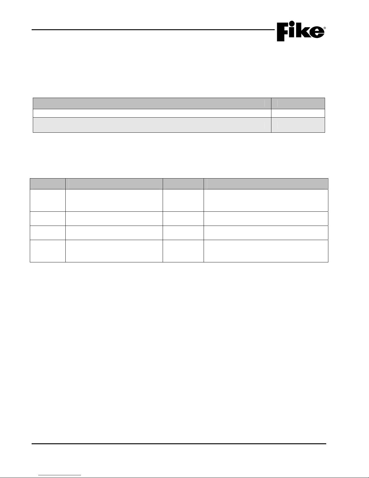
Exhibit 1-1: Related Documentation
Document Title Part Number
CyberCat Addressable Fire Alarm Control System Installation Manual 06-326
CyberCat Addressable Fire Alarm Control System Operation & Maintenance Manual 06-326-2
1.5 REVISION HISTORY
Document Title: CyberCat Addressable Fire Alarm System Programming Manual
Document Reorder Number: 06-539
Revision Section Date Reason for Change
Separated manual into separate
0 All Sections 05/2011
Installation, Operation and Programming
Manuals
1 All Sections 12/2011 Added Mass Notification Functions
2 All Sections 06/2012 Added FAAST Detector Functions
Added programming features for AHU
3 Sections 1, 2, 4, and Appendix A 08/2013
restart, audio sync, and MNS activation via
SLC input modules.
1-2 CyberCat 254/1016 Programming Manual
Rev 3, 08/2013 P/N: 06-539

2.0 C-Linx PROGRAMMING OPTIONS
2.1 UNDERSTANDING CYBERCAT
The CyberCat system is equipped with an extensive list of configuration parameters. Changes to these
parameters can be made either directly at the panel using its integral configuration menus, or by using the
system’s PC configuration software C-Linx. Not all of the system operating parameters can be set using the
panel’s configuration menus. Section 4.0 of this manual provides a complete description of the configuration
parameters that can changed at the panel.
To set all operating parameters for the system, you must use the panel’s PC programming software C-Linx.
Section 2.2 provides a complete listing of the programming features that are available through C-Linx for your
reference. Refer to Fike document 06-448, “C-Linx Configuration Software” for software details.
It is important to keep in mind that any changes made to the system configuration directly through the panel’s
configuration menus will only be stored within the panel’s on-board memory. To retain a back-up copy of the
system programming, you should download the latest configuration settings from the panel each time you
service the system.
CyberCat 254/1016 Programming Manual 2-1
P/N: 06-539 Rev 3, 08/2013
2.0 C-Linx PROGRAMMING OPTIONS
2.2 SOFTWARE PROGRAMMING FEATURES
The following tables identify the configurable features that can be changed by using the panel’s programming
software C-Linx. The table also identifies features that are available, but not permitted to be used per the
CyberCat system’s UL listing.
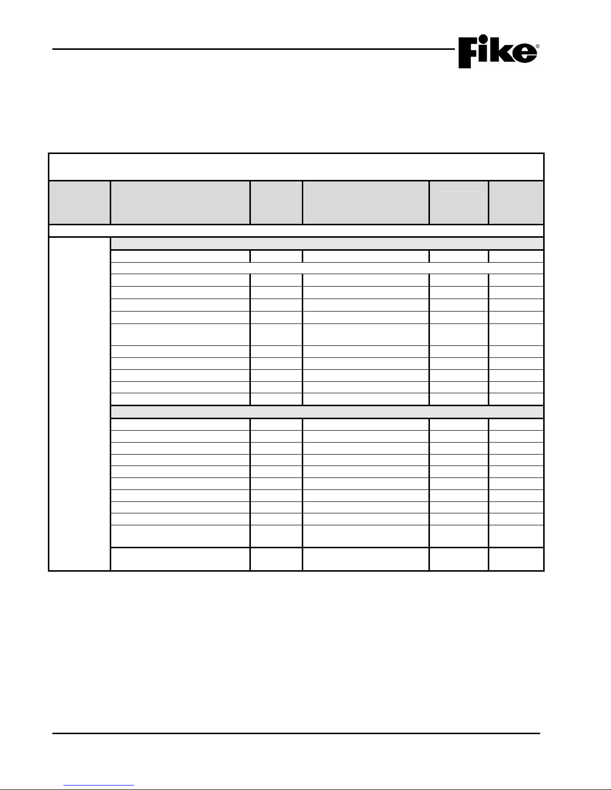
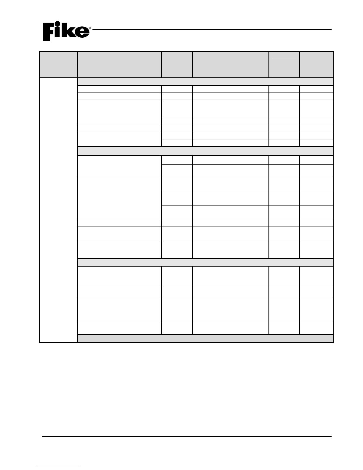
Exhibit 2-1: Programming Features
NOTICE TO USERS, INSTALLERS, AUTHORITIES HAVING JURISDICTION, AND OTHER INVOLVED PARTIES
This product incorporates field-programmable software. In order for the product to comply with the requirements in the Standard for Control Units and Accessories for
Circuit or
Component Program Feature or Option
Main Board Configuration Options
MISC.
Notes:
1. City of Chicago does not allow use of Drill, Silence and Acknowledge switches.
2. Can only be changed with Factory Level password.
3. Not used on the CyberCat 254 panel.
4. Voice Panel Priorities allows the user to program a priority scheme for Fire events and MNS events. 0 is used for systems
5. Locality setting is configured for operation of local jurisdiction requirements for Boston, Chicago and New York only. Outside of
6. Alert, Evac, Page and MNS Active manual activation events are broadcast to the SLC’s to activate or de-activate outputs
7. If device on SLC has an internal error the panel produces a trouble state (Yes) and does not just log the event into its history
8. Level 2 ground fault detection required for use with solenoids.
Fire Alarm Systems, UL 864, certain programming features or options must be limited to specific values or not used at all as indicated below.
Permitted
in UL
864?
(Y/N)
Possible Settings
(Defaults shown bold)
Miscellaneous Options
AC Trouble Delay Y
0-30 hours, Default 2 hours
1–3
Voice Panel Priorities
• Alarm
• Test Alarm
• Supervisory
• Process
Y
Y
Y
Y
Voice City Y
0-254, Default 4
0-254, Default 5
0-254, Default 6
0-254, Default 7
Standard / Boston / Chicago
4
4
4
4
Standard 5
/ New York
Voice States on Loop Y
Fan Restart Y
Drill/Silence/Acknowledge N
Auto Message Y
Walktest Y
Enabled / Disabled
Automatic/Manual
Enabled / Disabled
Enabled / Disabled
Enabled / Disabled
6
Enabled 1,2
Supervision Options
Transformer Y
Loop Style (SLC) Y
Ground Fault Level 1 N
Ground Fault Level 2 N
Main Battery Y
Auxiliary Battery Y
Auxiliary Loop Module Present Y
Auxiliary Power Module Present Y
Eclipse Device Error Trouble Y
AHU Fire Dept Key Required for
Y
120VAC / 240VAC
4, 6, or 7 (Class B, A or X)
Enabled / Disabled
Enabled / Disabled
Supervised / Unsupervised
Supervised / Unsupervised
Enabled / Disabled
Enabled / Disabled
Enabled / Disabled
Enabled / Disabled
Enabled 2
Enabled 2,8
3
3
3
Enabled 7
AHU Restart
Battery Cutoff Y Loop # and Address #
(L: 1-4 Address: 0-254)
where priority is not required (0 = None; 1 = Highest and 254 = Lowest).
these jurisdictions, the setting should be set to Standard.
connected to the SLC.
buffer (No). (i.e. Checksum Error)
Settings
permitted
in UL 864 Notes
2-2 CyberCat 254/1016 Programming Manual
Rev 3, 08/2013 P/N: 06-539
2.0 C-Linx PROGRAMMING OPTIONS
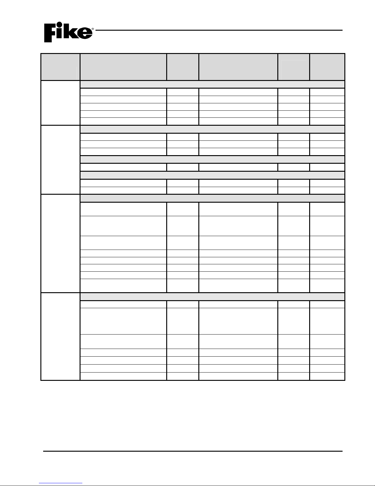
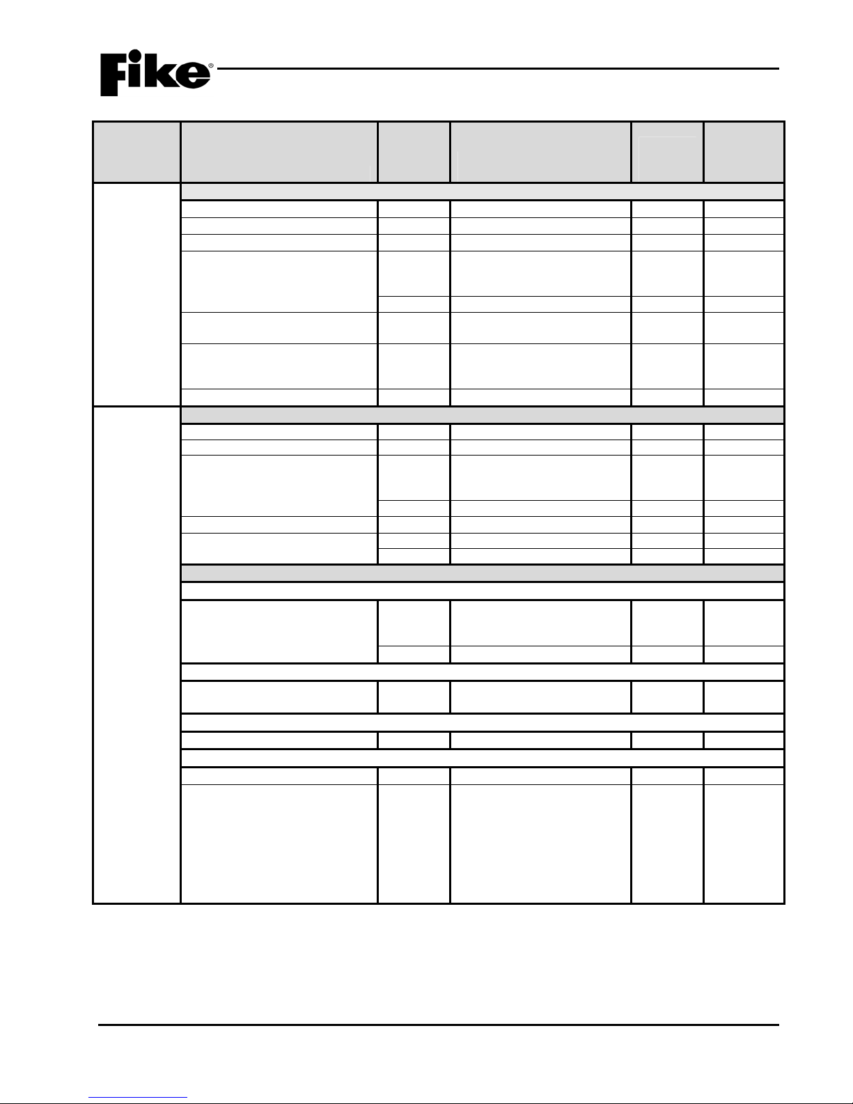
Exhibit 2-2: Programming Features Cont.
Permitted
in UL
Circuit or
Component Program Feature or Option
MISC.
Silence Options
Unsilence Time Y
Silence Reminder Y
Silence Inhibit Y
Positive Alarm Sequence Y
Silence Mode Y
Time
Functions
Alarm Sensitivity Changes
Daytime Sensitivities start/stop Y 12:00 AM – 12:00 AM
864?
(Y/N)
Possible Settings
(Defaults shown bold)
1-24 hours
Enabled / Disabled
Enabled / Disabled
Enabled / Disabled
UL
Days that use daytime sensitivity Y Sunday – Saturday
Use Daylight Savings Time Y
Enabled / Disabled
Holiday Schedule
Night time sensitivity Y 20 days total (mm/dd/yyyy) 4
DACT Auto Test
DACT Auto test start hour Y
DACT Auto test period (hrs.) Y
0 – 23 (2 default)
0 - 24
NAC P10 and P11 (NAC 1 & NAC 2)
Sync Protocol Y
NO / Gentex / System
Sensor / Wheelock
State (Activation) Y
Alarm / Pre-Alarm 1 / PreAlarm 2 / Supervisory /
Trouble / Process
Silenceable Y
Silenceable / Non
silenceable
Zone Assignment Y
Circuit Y
Drill Y
Walktest Y
Panel Sync Protocol Y
1 – 254
Enabled / Disabled
Enabled / Disabled
Enabled / Disabled
Gentex / System Sensor /
Wheelock
Relays
P2 Main Board Relay
Relay Selection Y
State (Activation) Y
R1 / R2
Alarm / Pre-Al arm 1 / Pre-
Alarm 2 / Supervisory /
Trouble / Process / Zone
Disable
Silenceable Y
Non-Silenceable /
Silenceable
Relay Y
Zone Assignment Y
Circuit Y
Drill Y
Notes:
1. An audible signal that has been silenced at the protected premises shall automatically resound and remain energized until
silenced and retransmitted the signal to any supervising station to which the original signal was transmitted, as applicable, at
least once every 24 hours until the condition is corrected and the product is restored to the normal supervisory condition.
2. If synchronization is selected, both NAC circuits will use the same sync protocol.
3. Refer to Fike document 06-186 for compatible sync protocol.
4. Only allows the installer to assign the night time sensitivity to a different obscuration level than during normal working hours.
No other functions are affected or disabled.
5. Allows on board relays to be configured from the default setting of Alarm for R1 and Supervisory for R2 to the states listed in
State (Activation).
Enabled / Disabled
1 – 254
Enabled / Disabled
Enabled / Disabled
Settings
permitted
in UL 864 Notes
UL 1
2,3
5
CyberCat 254/1016 Programming Manual 2-3
P/N: 06-539 Rev 3, 08/2013

2.0 C-Linx PROGRAMMING OPTIONS
Exhibit 2-3: Programming Features Cont.
Permitted
in UL
Circuit or
Component Program Feature or Option
Relays
Zones Zones Y
P12
Relay Selection Y A / B / C / D
Module Y
State Y Alarm / Pre-Alarm 1 / Pre-
Restart Delay Y
Silenceable Y
Zone Assignment Y
Relay Y
Drill Y
P13
Relay Selection Y A / B / C / D
Module Y
State Y Alarm / Pre-Alarm 1 / Pre-
Restart Delay Y
Silenceable Y
Zone Assignment Y
Relay Y
Drill Y
Type Y
Custom Message Y 20 character user defined
Voice EVAC Mapping Y Zones 1 - 254
Voice Alert Mapping Y Zones 1 - 254
Zone Enabled Y
Zone Chimes Y Assign chime code to zones
864?
(Y/N)
No Module Installed / CRM4 /
CRPM (Opt 1) / CRPM (Opt
2) / Fire Communicator
Alarm 2 / Supervisory /
Trouble / Process / Zone
Disable
0 – 250 (sec)
Non-Silenceable /
Silenceable
1 – 254
Enabled / Disabled
Enabled / Disabled
No Module Installed / CRM4 /
CRPM (Opt 1) / CRPM (Opt
2) / Network Interface Card
Alarm 2 / Supervisory /
Trouble / Process / Zone
Disable
0 – 250 (sec)
Non-Silenceable /
Silenceable
1 – 254
Enabled / Disabled
Enabled / Disabled
1 – 254
Alarm Zone
Enabled / Disabled
Possible Settings
(Defaults shown bold)
Settings
permitted
in UL 864 Notes
2-4 CyberCat 254/1016 Programming Manual
Rev 3, 08/2013 P/N: 06-539

2.0 C-Linx PROGRAMMING OPTIONS
Exhibit 2-4: Programming Features Cont.
Permitted
in UL
Circuit or
Component Program Feature or Option
864?
(Y/N)
Possible Settings
(Defaults shown bold)
Peripherals Message Y 20 character user defined
Settings
permitted
in UL 864 Notes
1
(PERIPHERAL ID 02)
Zone Assignment Y
Supervision Y
Voice Y
Status Y
History Transmit Y
History Packing Y
History Message Y
Dual Channel Voice Y
Notes:
1. Peripheral device must be added to the Peripherals list before these configuration options are available.
2. This command contains status for Alarm, Supervisory, Trouble and all other states. Peripheral devices that have firmware
version before 3.00 should set this variable to STD, which is the original CyberCat format. The ESP selection refers to an
“Expanded” format. Peripheral devices with 3.00 firmware or newer will used this command. The EXP setting speeds up
operation of the peripheral bus.
3. If set to COMPACT, a message filter within the panel is used to prevent transmission of certain history record events, including
the NEW DEVICE history messages. This is done so that the peripherals do not display messages that are not required. If set
to VERBOSE, all history messages are transmitted.
4. HISTORY PACKING refers to how many history records are transmitted back-to-back with minimum time in between. If set to
UNPACKED, history records are sent one at a time. If set to PACKED, up to 50 history records are sent back-to-back. This
will speed up transmission of large amounts of history data.
5. HISTORY MESSAGE refers to what kind of data is packed into the history command. If set to STD (standard), data is packed
as with previous versions. If set to EXP (expanded), both lines 1 and 2 of the history data as shown on the LCD of the panel is
packed into the history command.
0 - 254
Unsupervised / Supervised
No Voice / EVAX / Fike
STD / EXP
Compact / Verbose
Unpacked / Packed
STD / EXP
Enabled / Disabled
1
1
2
3
4
5
CyberCat 254/1016 Programming Manual 2-5
P/N: 06-539 Rev 3, 08/2013

2.0 C-Linx PROGRAMMING OPTIONS
Exhibit 2-5: Programming Features Cont.
Permitted
Circuit or
Component Program Feature or Option
Network
Network Settings
Network Address (Panel ID) Y
Network Module Type Y
Network Panel Message Y 20 character user defined
in UL
864?
(Y/N)
Possible Settings
(Defaults shown bold)
1 - 128
None / First / Middle / Last
(CUSTOM MSG PANEL 001)
Settings
permitted
in UL 864 Notes
1
where ZZZ = zone number
Network Switch Operation Y
Network Switch IDs Y
Global / Local
1 – 128
2
Selects which network
devices the panel will receive
switch commands from.
Network Zones Y 1 – 254 3
Panel Supervision Y 1 – 254 4
Wiring Style Y
History Y
Style 4 / Style 7
Single / Multiple
Ethernet Settings
Source IP Address Y
000.000.000.000
5
User Defined
Destination IP Address Y
000.000.000.000
6
User Defined
Supervision IP Address Y
000.000.000.000
7
User Defined
Panel IP Supervision Y
History Transmits Y
000.000.000.000
1 – 10
4
(Fike recommends 2)
Supervision Timeout Y 1 – 59 (Sec., Min., Hour)
4 min. default
IP Time Y
IP Time Disabled
8
Accept IP Time
Send IP Time
Notes:
1. Defines the location of the panel with respect to others on the network.
2. Defines if the respective panel will react to Reset, Silence, Acknowledge, and Drill commands received from other networked
panels.
3. Defines which network zones will participate in the local panel zone(s).
4. Defines which network panel(s) the selected panel should supervise.
5. Defines the unique Internet Protocol (IP) address for the selected panel.
6. Defines the unique Internet Protocol (IP) address for the panel that is to receive history events from the selected panel.
7. Defines the unique Internet Protocol (IP) address for the panel that is to supervision responses from the selected panel.
8. Used to synchronize panel time over the network.
2-6 CyberCat 254/1016 Programming Manual
Rev 3, 08/2013 P/N: 06-539

2.0 C-Linx PROGRAMMING OPTIONS
Exhibit 2-6: Programming Features Cont.
Permitted
in UL
Circuit or
Component Program Feature or Option
Defaults
(Photo
Sensor)
Common
Loop Number of Device Y
Address of Device Y
Custom Message Y 60 character user defined
Zone Assignments Y
Alarm Verification Y Time: 0 – 60 seconds
Sensitivity
Pre-Alarm 1 & 2 Levels Y
Alarm Levels Y
Drift Compensation
(Warning/Trouble)
Walktest Y
Device Summing
Broadcast Thresholds for
Summing (%OBS)
Summing Activation Level
(%OBS)
Summing Broadcast State No
Summing Addresses No 1 – 8 (Device addresses to
Notes:
1. CyberCat 254 has only one (1) addressable loop. CyberCat 1016 can have up to four (4) addressable loops.
2. Can be assigned to 4 discrete zones, 2 zone ranges or 1 range and 2 discrete zones.
3. Pre-Alarm 2 setting must always be set equal or higher than Pre-Alarm 1 setting.
4. High setting must be equal or lower obscuration setting than Low setting.
5. Can be set in 1% increments. Trouble must be higher % than Warning.
864?
(Y/N)
Possible Settings
(Defaults shown bold)
1 - 4
1 – 254
(1-001 PHOTO DETECT
Loop 1 - Address 001)
Y
Default / User Defined
1 – 254
Y
Enabled / Disabled
Enabled / Disabled
Y
0.5%/ft. – 4.0%/ft.
(0.1%/ft. increments)
Acclimate: 1.3%/ft. – 3.6%/ft.
(High 2.0% - Low 2.5%)
Y
Day/Night: 1.3%/ft. – 3.6%/ft.
(Day 3.6% - Night 3.6%)
Y
Alarm / Supervisory /
Supervisory NL
Y 50 – 100%
Warning 80%/Trouble 100%
Walktest at Alarm Level /
Walktest with IR / Walktest at
1.3%
N
Enabled / Disabled
(8 levels 0.5%/ft. – 4.0%/ft. in
0.1%/ft. increments)
N 1.0 – 10%/ft.
(0.5%/ft. increments)
Disabled / Alarm / Summing
Alarm / Supervisory Latching
/ Supervisory Non-Latching /
Pre-Alarm 1 / Pre-Alarm 2
participate in summing
group)
Settings
permitted
in UL 864 Notes
1
2
3
4
5
CyberCat 254/1016 Programming Manual 2-7
P/N: 06-539 Rev 3, 08/2013

2.0 C-Linx PROGRAMMING OPTIONS
Exhibit 2-7: Programming Features Cont.
Permitted
Circuit or
Component Program Feature or Option
Defaults
(Photo
Sensor)
Remote Annunciator
Annunciator Type Y
Silenceable Y
Positive Alarm Sequence (PAS) Y
Output Settings – Priority Row Y 1 – 8 1
Activation State Y
Action Type Y No Action / Activate on
in UL
864?
(Y/N)
Possible Settings
(Defaults shown bold)
None / Remote LED –
Follows Red / Remote LED –
Follows Green / Remote LED
– Follows Amber / Remote
LED – Independent /
Sounder Base / Relay Base
Silenceable / Non- Silence
Disabled / Enabled
No State / Alarm / Summing
Alarm / Test Alarm / Alarm
Verification ON / Pre-Alarm 1
/ Pre-Alarm 2 / Supervisory /
Trouble / Open Circuit
Trouble / Short Circuit
Trouble / Low Power Trouble
/ Maintenance Trouble /
Process / Zone Disable
Switch / Voice Alert / Voice
Evacuate / Voice Page /
Voice Play Message ID
Settings
permitted
in UL 864 Notes
1,2
2
2
Any of 3 zones / Activate
on All of 3 zones / Activate
on Specific Device /
Activate on multiple
priority rows active
Output Pattern Y OFF / ON Continuous /
Slow / Fast / Temporal /
Walktest / Alert / Action
State Counter Y 1 – 16
Notes:
1. If annunciator type is set to Independent Operation, Sounder Base, or Relay Base an 8-row priority table will be displayed.
Table values are set using the Output Settings fields.
2. If annunciator type is set to Sounder Base, Silence and Positive Alarm Sequence (PAS) options will be displayed.
2-8 CyberCat 254/1016 Programming Manual
Rev 3, 08/2013 P/N: 06-539
2.0 C-Linx PROGRAMMING OPTIONS
Exhibit 2-8: Programming Features Cont.
Permitted
in UL
Circuit or
Component Program Feature or Option
Defaults
(Photo/Heat
Sensor)
Common
Loop Number of Device Y
Address of Device Y
Custom Message Y
Zone Assignments Y
Alarm Verification Y
Sensitivity
Pre-Alarm 1 & 2 Levels Y
Alarm Levels Y
Flame Enhance N
Drift Compensation
(Warning/Trouble)
Walktest Y
Device Summing
Broadcast Thresholds for
Summing (%OBS)
Summing Activation Level
(%OBS)
Summing Broadcast State N
Summing Addresses N
Remote Annunciator (See Exhibit 2-7 for programming features)
Notes:
1. CyberCat 254 has only one (1) addressable loop. CyberCat 1016 can have up to four (4) addressable loops.
2. Can be assigned to 4 discrete zones, 2 zone ranges or 1 range and 2 discrete zones.
3. Pre-Alarm 2 setting must always be set equal or higher than Pre-Alarm 1 setting.
4. High setting must be equal or lower obscuration setting than Low setting.
5. Can be set in 1% increments. Trouble must be higher % than Warning.
864?
(Y/N)
Y
Y
Y
Y
Y
Y
N
N
Possible Settings
(Defaults shown bold)
1 - 4
1 – 254
60 character user defined
(1-001 PHO/HT DETECT
Loop 1 - Address 001)
Default / User Defined
1 – 254
Time: 0 – 60 seconds
Enabled / Disabled
Enabled / Disabled
0.5%/ft. – 4.0%/ft.
(0.1%/ft. increments)
Acclimate: 1.3%/ft. – 3.6%/ft.
(High 2.0% - Low 2.5%)
Day/Night: 1.3%/ft. – 3.6%/ft.
(Day 3.6% - Night 3.6%)
Alarm / Supervisory /
Supervisory NL
ON / OFF
50 – 100%
Warning 80%/Trouble 100%
Walktest at Alarm Level /
Walktest with IR / Walktest at
1.3%
Enabled / Disabled
(8 levels 0.5%/ft. – 4.0%/ft. in
0.1%/ft. increments)
1.0 – 10%/ft.
(0.5%/ft. increments)
Disabled / Alarm / Summing
Alarm / Supervisory Latching /
Supervisory Non-Latching /
Pre-Alarm 1 / Pre-Alarm 2
1 – 8 (Device addresses to
participate in summing group)
Settings
permitted
in UL 864 Notes
1
2
3
4
5
CyberCat 254/1016 Programming Manual 2-9
P/N: 06-539 Rev 3, 08/2013

2.0 C-Linx PROGRAMMING OPTIONS
Exhibit 2-9: Programming Features Cont.
Permitted
in UL
Circuit or
Component Program Feature or Option
Defaults
(Photo/Duct
Sensor)
Common
Loop Number of Device Y
Address of Device Y
Custom Message Y 60 character user defined
Zone Assignments Y
Alarm Verification Y Time: 0 – 60 seconds
Sensitivity
Pre-Alarm 1 & 2 Levels Y
Alarm Levels Y
Drift Compensation
(Warning/Trouble)
Walktest Y
Device Summing
Broadcast Thresholds for
Summing (%OBS)
Summing Activation Level
(%OBS)
Summing Broadcast State N
Summing Addresses N 1 – 8 (Device addresses to
Remote Annunciator (See Exhibit 2-7 for programming features)
Notes:
1. CyberCat 254 has only one (1) addressable loop. CyberCat 1016 can have up to four (4) addressable loops.
2. Can be assigned to 4 discrete zones, 2 zone ranges or 1 range and 2 discrete zones.
3. Pre-Alarm 2 setting must always be set equal or higher than Pre-Alarm 1 setting.
4. High setting must be equal or lower obscuration setting than Low setting.
5. Can be set in 1% increments. Trouble must be higher % than Warning.
864?
(Y/N)
Possible Settings
(Defaults shown bold)
1 - 4
1 – 254
(1-001 DUCT DETECT
Loop 1 - Address 001)
Y
Default / User Defined
1 – 254
Y
Enabled / Disabled
Enabled / Disabled
Y
0.6%/ft. – 4.0%/ft.
(0.1%/ft. increments)
Acclimate: 0.8%/ft. – 3.4%/ft.
(High 2.0% - Low 2.5%)
Y
Day/Night: 0.8%/ft. – 3.4%/ft.
(Day 1.5% - Night 3.4%)
Y Alarm / Supervisory /
Supervisory NL
Y 50 – 100%
Warning 80%/Trouble 100%
Walktest at Alarm Level /
Walktest with IR / Walktest at
1.3%
N
Enabled / Disabled
(8 levels 0.5%/ft. – 4.0%/ft. in
0.1%/ft. increments)
N 1.0 – 10%/ft.
(0.5%/ft. increments)
Disabled / Alarm / Summing
Alarm / Supervisory Latching
/ Supervisory Non-Latching /
Pre-Alarm 1 / Pre-Alarm 2
participate in summing group)
Settings
permitted
in UL 864 Notes
1
2
3
4
5
2-10 CyberCat 254/1016 Programming Manual
Rev 3, 08/2013 P/N: 06-539

2.0 C-Linx PROGRAMMING OPTIONS
Exhibit 2-10: Programming Features Cont.
Permitted
in UL
Circuit or
Component Program Feature or Option
Defaults
(Heat
Sensor)
Common
Loop Number of Device Y
Address of Device Y
864?
(Y/N)
Possible Settings
(Defaults shown bold)
1 - 4
1 – 254
Custom Message Y 60 character user defined
(1-001 HEAT DETECT
Loop 1 - Address 001)
Y
Zone Assignments Y
Default / User Defined
1 – 254
Alarm Verification Y Time: 0 – 60 seconds
Y
Enabled / Disabled
Sensitivity
Pre-Alarm 1 & 2 Levels Y
Y
Enabled / Disabled
70°F - 190°F
(5°F increments)
Alarm Levels (Day/Night) Y
Fixed Temp: 135°F - 190°F
(5°F increments)
Y
Rate of Rise: 135°F - 174°F
(5°F increments)
Walktest Y
Walktest at 135°F / Walktest
with IR
Remote Annunciator (See Exhibit 2-7 for programming features)
Notes:
1. CyberCat 254 has only one (1) addressable loop. CyberCat 1016 can have up to four (4) addressable loops.
2. Can be assigned to 4 discrete zones, 2 zone ranges or 1 range and 2 discrete zones.
3. Pre-Alarm 2 setting must always be set equal or higher than Pre-Alarm 1 setting.
4. Rate of Rise temperature range is 135°F - 174°F. Fixed temperature operation will be used for detection above this ran ge.
Settings
permitted
in UL 864 Notes
1
2
3
4
4
CyberCat 254/1016 Programming Manual 2-11
P/N: 06-539 Rev 3, 08/2013

2.0 C-Linx PROGRAMMING OPTIONS
Exhibit 2-11: Programming Features Cont.
Permitted
in UL
Circuit or
Component Program Feature or Option
Defaults
(Ion Sensor)
Common
Loop Number of Device Y
Address of Device Y
Custom Message Y
Zone Assignments Y
Alarm Verification Y
Sensitivity
Pre-Alarm 1 & 2 Levels Y
Alarm Levels Y
Drift Compensation Y
Walktest Y
Device Summing
Broadcast Thresholds for
Summing (%OBS)
Summing Activation Level
(%OBS)
Summing Broadcast State N
Summing Addresses N
Remote Annunciator (See Exhibit 2-7 for programming features)
Notes:
1. CyberCat 254 has only one (1) addressable loop. CyberCat 1016 can have up to four (4) addressable loops.
2. Can be assigned to 4 discrete zones, 2 zone ranges or 1 range and 2 discrete zones.
3. Pre-Alarm 2 setting must always be set equal or higher than Pre-Alarm 1 setting.
4. High setting must be equal or lower obscuration setting than Low setting.
5. Can be set in 1% increments. Trouble must be higher % than Warning.
864?
(Y/N)
Y
Y
Y
Y
Y
N
N
N
Possible Settings
(Defaults shown bold)
1 - 4
1 – 254
60 character user defined
(1-001 ION DETECT
Loop 1 - Address 001)
Default/User Defined
1 – 254
Time: 0 – 60 seconds
Enabled / Disabled
Enabled / Disabled
100 – 40 Microns
(5 Micron increments)
Acclimate: 80 – 50 Microns
(5 Micron increments)
Day/Night: 80 – 50 Microns
(5 Micron increments)
Alarm / Supervisory /
Supervisory NL
Smolder Enhance Off /
Smolder Enhance On
50 – 100%
Warning 80%/Trouble 100%
Walktest at Alarm Level /
Walktest with IR / Walktest at
1.3%
Enabled / Disabled
(8 levels 0.5%/ft. – 4.0%/ft. in
0.1%/ft. increments)
1.0 – 10%/ft.
(0.5%/ft. increments)
Disabled / Alarm/Summing
Alarm / Supervisory Latching /
Supervisory Non-Latching /
Pre-Alarm 1 / Pre-Alarm 2
1 – 8 (Device addresses to
participate in summing group)
Settings
permitted
in UL 864 Notes
1
2
3
4
5
2-12 CyberCat 254/1016 Programming Manual
Rev 3, 08/2013 P/N: 06-539

2.0 C-Linx PROGRAMMING OPTIONS
Exhibit 2-12: Programming Features Cont.
Permitted
Circuit or
Component Program Feature or Option
Defaults
(Monitor
Module)
Loop Number of Device Y
Address of Device Y
Custom Message Y 60 character user defined
in UL
864?
(Y/N)
Possible Settings
(Defaults shown bold)
1 - 4
1 – 254
Settings
permitted
in UL 864 Notes
1
(1-001 INPUT MANALRM
Loop 1 - Address 001)
Y
Zone Assignments Y
Input Function Type Y
Default / User Defined
1 – 254
No Input Function /
2
ManAlarm / Detection/
Waterflow /Pre-Alarm 1 / PreAlarm 2 / Supervisory /
Trouble / Process / PAS
Inhibit / Reset / Silence /
Acknowledge / Drill / Zone
Disable / Fan Restart /
Smoke Control Confirmation /
Manual Alarm Stage 2 / AHU
Fie Dept Key / Voice Alert /
Voice Evacuation / Voice
Play Message ID / MNS Play
Message ID
Y Verify Time: 0 – 255 seconds 3
Y
Y
Latching / Non-Latching
Normally Open / Normally
4
5
Closed
Y
Class B Contact / Class A
Latching
Y
No Short Detection / Short
Detection
Voice/MNS Priority Y
Msg 1 ID Y
Msg 2 ID Y
MNS Timeout Y
Notes:
1. CyberCat 254 has only one (1) addressable loop. CyberCat 1016 can have up to four (4) addressable loops.
2. Can be assigned to 4 discrete zones, 2 zone ranges or 1 range and 2 discrete zones.
3. If monitor module function type is set to Detection, an alarm verification time can be set.
4. Either = PA1, PA2, Supervisory, Trouble, Process, PAS Inhibit; Non-Latch = Reset, Silence, Acknowledge, Zone Disable, Fan
Restart; Latching = ManAlarm, Detection, Waterflow, Drill.
5. NO Contacts = Detection, Manual Alarm, Reset, Supervisory; NO/NC Contacts = Process, Waterflow, PA1, PA2, Trouble, Drill,
Silence, Acknowledge, Zone Disable, PAS Inhibit, Fan Restart.
6. Priority field becomes available only when Input Function is set to a Voice or MNS function.
7. Priority setting cannot be set the same as the panel priority settings for Alarm, Test Alarm, Supervisory, and Process.
8. Message ID field becomes available only when Input Function is set to Voice or MNS Play Message ID.
9. MNS Timeout field becomes available only when input Function is set to MNS Play Message ID.
1 - 255
0 - 16
0 - 16
0 - 250
6, 7
8
8
9
CyberCat 254/1016 Programming Manual 2-13
P/N: 06-539 Rev 3, 08/2013

2.0 C-Linx PROGRAMMING OPTIONS
Exhibit 2-13: Programming Features Cont.
Permitted
in UL
Circuit or
Component Program Feature or Option
Defaults
(Mini Monitor
Module)
Loop Number of Device Y
Address of Device Y
Custom Message Y 60 character user defined
864?
(Y/N)
Possible Settings
(Defaults shown bold)
1 - 4
1 – 254
(1-001 MINI MANALRM
Loop 1 - Address 001)
Custom Message Y
Zone Assignments Y
Input Function Type Y
Default / User Defined
1 – 254
No Input Function /
ManAlarm / Detection/
Waterflow /Pre-Alarm 1 / PreAlarm 2 / Supervisory /
Trouble / Process / PAS
Inhibit / Reset / Silence /
Acknowledge / Drill / Zone
Disable / Fan Restart /
Smoke Control Confirmation /
Manual Alarm Stage 2 / AHU
Fire Dept Key / Voice Alert /
Voice Evacuation / Voice
Play Message ID / MNS Play
Message ID
Y Verify Time: 0 – 255 seconds 3
Y
Y
Latching / Non-Latching
Normally Open / Normally
Closed
Y
No Short Detection / Short
Detection
1 - 255
0 - 16
0 - 16
0 - 250
1 - 4
1 – 254
Defaults
(Pull Station
Module)
Voice/MNS Priority Y
Msg 1 ID Y
Msg 2 ID Y
MNS Timeout Y
Loop Number of Device Y
Address of Device Y
Custom Message Y 60 character user defined
(1-001 PULL STATION
Loop 1 - Address 001)
Custom Message Y
Zone Assignments Y
Input Function Y
Default/User Defined
1 – 254
No Input Function / Manual
Alarm
Notes:
1. CyberCat 254 has only one (1) addressable loop. CyberCat 1016 can have up to four (4) addressable loops.
2. Can be assigned to 4 discrete zones, 2 zone ranges or 1 range and 2 discrete zones.
3. If monitor module function type is set to Detection, an alarm verification time can be set.
4. Either = PA1, PA2, Supervisory, Trouble, Process, PAS Inhibit; Non-Latch = Reset, Silence, Acknowledge, Zone Disable, Fan
Restart; Latching = ManAlarm, Detection, Waterflow, Drill.
5. NO Contacts = Detection, Manual Alarm, Reset, Supervisory; NO/NC Contacts = Process, Waterflow, PA1, PA2, Trouble, Drill,
Silence, Acknowledge, Zone Disable, PAS Inhibit, Fan Restart.
6. Priority field becomes available only when Input Function is set to a Voice or MNS function.
7. Priority setting cannot be set the same as the panel priority settings for Alarm, Test Alarm, Supervisory, and Process.
8. Message ID field becomes available only when Input Function is set to Voice or MNS Play Message ID.
9. MNS Timeout field becomes available only when input Function is set to MNS Play Message ID.
Settings
permitted
in UL 864 Notes
1
2
4
5
6, 7
8
8
9
1
2
2-14 CyberCat 254/1016 Programming Manual
Rev 3, 08/2013 P/N: 06-539

2.0 C-Linx PROGRAMMING OPTIONS
Exhibit 2-14: Programming Features Cont.
Permitted
in UL
Circuit or
Component Program Feature or Option
Defaults
(Supervised
Control
Module)
Common
Loop Number of Device Y
Address of Device Y
Output Y
Custom Message Y 60 character user defined
Custom Message Y
Zone Assignments
(device troubles)
Defaults for Pre-Action Y
Defaults for 2 Stage Alarm N
Drill Output Pattern Y
Output Silenceable Y
Positive Alarm Sequencing
(PAS)
Power Supply Monitor Y
Output Control
Activation State Y
Action Type Y
Output Pattern Y
Output Pattern Set Y
State Counter Y
Zone Assignments (activation) Y 0 - 255 5
Notes:
1. CyberCat 254 has only one (1) addressable loop. CyberCat 1016 can have up to four (4) addressable loops.
2. Can be assigned to 4 discrete zones, 2 zone ranges or 1 range and 2 discrete zones.
3. Modifies control module configuration for use with Pre-Action solenoid.
4. If selected, the control module configuration will be modified for 2-Stage Alarm Operation (City of Chicago).
5. Can be assigned to any 3 zones, 254 any zone, or 255 any zone (non-disable).
864?
(Y/N)
Y
Y
Possible Settings
(Defaults shown bold)
1 - 4
1 – 254
Enabled/Disabled
(1-001 OUTPUT MODULE
Loop 1 - Address 001)
Default/User Defined
1 – 254
Yes/No
Yes/No
Drill Disabled / On
Continuous / Slow / Fast /
Temporal
Silenceable/Non-Silenceable
Disabled / Enabled
Enabled/Disabled
Alarm / Summing Alarm /
Test Alarm / Alarm
Verification ON / Pre-Alarm 1
/ Pre-Alarm 2 / Supervisory /
Trouble / Open Circuit
Trouble / Short Circuit
Trouble / Low Power Trouble
/ Maintenance Trouble /
Process / Zone Disable
Switch / Voice Alert / Voice
Evacuate / Voice Page /
Voice Play Message ID /
MNS Message Active
No Action / Activate on Any
of 3 zones / Activate on All of
3 zones / Activate on Specific
Device / Activate on multiple
priority rows active
OFF / ON Continuous / Slow
/ Fast / Temporal / Walktest /
Times / Custom Defined
1 - 3
1 – 16
Settings
permitted
in UL 864 Notes
1
2
3
4
CyberCat 254/1016 Programming Manual 2-15
P/N: 06-539 Rev 3, 08/2013

2.0 C-Linx PROGRAMMING OPTIONS
Exhibit 2-15: Programming Features Cont.
Permitted
in UL
Circuit or
Component Program Feature or Option
Defaults
(Relay
Module)
Common
Loop Number of Device Y
Address of Device Y
Output Y
Custom Message Y 60 character user defined
Zone Assignments (Device
Troubles)
AHU Shutdown Relay Y Enabled / Disabled
Restart Delay Y
Misc. Options
(feedback relay monitoring)
Positive Alarm Sequencing
(PAS)
Output Control (Note 6)
Activation State Y
Action Type Y
Relay State Y
Timeout Y 0 – 80 minutes 2
State Counter Y
Output Y
Drill Y
Zone Assignments (activation) Y 0 - 255 3
Notes:
1. CyberCat 254 has only one (1) addressable loop. CyberCat 1016 can have up to four (4) addressable loops.
2. Timeout delay becomes active if relay state is set to ‘Time Delay’.
3. Can be assigned to any 3 zones, 254 any zone, or 255 any zone (non-disable).
4. Restart delay becomes active if relay is configured for AHU shutdown operation.
5. These options are not available if relay is configured for AHU shutdown operation.
6. Output control is disabled if relay is set for AHU Shutdown operation.
864?
(Y/N)
Y
Y
Y
Y
Possible Settings
(Defaults shown bold)
1 - 4
1 – 254
Enabled/Disabled
(1-001 RELAY MODULE
Loop 1 - Address 001)
Default/User Defined
1 – 253
(4 zones available)
0 – 255 seconds
Not Monitored / Monitored
by dry contact / Independent
dry contact
Enabled / Disabled
Alarm / Summing Alarm /
Test Alarm / Alarm
Verification ON / Pre-Alarm 1
/ Pre-Alarm 2 / Supervisory /
Trouble / Open Circuit
Trouble / Short Circuit
Trouble / Low Power Trouble
/ Maintenance Trouble /
Process / Zone Disable
Switch / Voice Alert / Voice
Evacuate / Voice Page /
Voice Play Message ID /
MNS Message Active
No Action / Activate on Any
of 3 zones / Activate on All of
3 zones / Activate on Specific
Device / Activate on multiple
priority rows active
ON / OFF / Timed / Time
Delay
1 – 16
Silenceable/Non-Silenceable
Enabled / Disabled
Settings
permitted
in UL 864 Notes
1
4
5
5
2-16 CyberCat 254/1016 Programming Manual
Rev 3, 08/2013 P/N: 06-539
2.0 C-Linx PROGRAMMING OPTIONS
Exhibit 2-16: Programming Features Cont.
Permitted
in UL
Circuit or
Component Program Feature or Option
Defaults
(Releasing
Module)
Common
Loop Number of Device Y
Address of Device Y
Output Y
864?
(Y/N)
Possible Settings
(Defaults shown bold)
1 - 4
1 – 254
Enabled/Disabled
Custom Message Y 60 character user defined
(1-001 RELEASING MOD
Loop 1 - Address 001)
Y
Zone Assignments Y
Default/User Defined
1 – 253
(2 zones available)
Output Type Y
No Output / Solenoid /
Expanded Solenoid /
Masterbox
No Output State / Alarm
1 - 4
Defaults
(FAAST
Detector)
Output State Y
Common
Loop Number of Device Y
Address of Device Y 1 – 254
Custom Message Y 60 character user defined
(1-001 FAAST DETECT
Loop 1 - Address 001)
Y
Zone Assignments Y
Walktest Y
Default/User Defined
1 – 253
Enabled / Disabled
Y 0.1% - 0.99645% ft. (slider)
States
State Assignments
Fire 2 / Fire 1 / Action 2 / Action
1 / Alert
Y
Disabled / Alarm / PreAlarm
2 / PreAlarm 1 / Supervisory /
Process
Y
Latching / Non-Latching
Alarm Verification Timers
Fire 2 / Fire 1 / Action 2 / Action
1 / Alert
Y
No Timer / Timer 1 / Timer 2
/ Timer 3
Verification Timer Values
Timer 1 / Timer 2 / Timer 3 Y
0 – 255 (seconds)
Acclimate
Acclimate Y
Acclimate High Range Y
Disabled / Enabled
Range 1-H
(0.00046%ft – 0.04980%ft)
Range 2-M
(0.05%ft – 0.09982%ft)
Range 3-M
(0.1%ft – 0.99645%ft)
Range 4-L
(1%ft – 3.98818%ft)
Notes:
1. CyberCat 254 has only one (1) addressable loop. CyberCat 1016 can have up to four (4) addressable loops.
2. Can be assigned to 4 discrete zones, 2 zone ranges or 1 range and 2 discrete zones.
3. Each detection level on the FAAST detector can be mapped to a panel state (user defined).
4. Each detection level can be configured as a latching or non-latching event. Must be latching if configured for Alarm.
5. Each detection level can be configured to initiate one of three Alarm Verification timers.
6. Allows you to set the high sensitivity level for the selected acclimate range.
Settings
permitted
in UL 864 Notes
1
1
2
3
4
5
6
CyberCat 254/1016 Programming Manual 2-17
P/N: 06-539 Rev 3, 08/2013

2.0 C-Linx PROGRAMMING OPTIONS
Exhibit 2-17: Programming Features Cont.
Circuit or
Component Program Feature or Option
Defaults
(FAAST
Day Sensitivity Levels
Fire 1 Y
Detector)
Copy from Night Sensitivity Y
Night Sensitivity
Fire 1 Y
Copy from Day Sensitivity Y
Miscellaneous
Particulate Level Display Y Fire 2 / Fire 1 / Action 2 /
Air Flow Trouble Boundary Y 0 – 100 (% off normal)
Air Flow Trouble Timer Y No Timer / Timer 1 / Timer
Security
Test Button Locked Y
Isolate Button Locked Y
Passcode Y
Device Disable (Isolate Button) Y
Reference Detector
Analog Broadcast Increasing
Step
Analog Broadcast Decreasing
Step
Reference Detector Y
Relays
Configuration (Relays 1 – 5) Y
Configuration (Relay 6) Y
Notes:
1. Set to 255 to disable Analog Broadcast.
2. Reference detector cannot use Acclimate feature.
Permitted
in UL
864?
(Y/N)
Y
Y
Y
Y
Possible Settings
(Defaults shown bold)
Range 1-H
(0.00046%ft – 0.04980%ft)
Range 2-M
(0.05%ft – 0.09982%ft)
Range 3-M
(0.1%ft – 0.99645%ft)
Range 4-L
(1%ft – 3.98818%ft)
Yes / No
Range 1-H
(0.00046%ft – 0.04980%ft)
Range 2-M
(0.05%ft – 0.09982%ft)
Range 3-M
(0.1%ft – 0.99645%ft)
Range 4-L
(1%ft – 3.98818%ft)
Yes / No
Action 1 / Alert
(20% default)
2 / Timer 3
Enabled / Disabled
Enabled / Disabled
0 – 9999 (1111 default)
Enabled / Disabled
0 - 255
0 - 255
0 - 254
Latching: Yes / No
Fire 2 / Fire 1 / Action 2 /
Action 1 / Alert
Latching: Yes / No
High Airflow / Low Airflow /
Isolate / Filter Minor / Filter
Urgent / Filter Door / Config /
Aspirator / Low Voltage /
Comm / Time / Sensor
Settings
permitted
in UL 864 Notes
1
1
2
2-18 CyberCat 254/1016 Programming Manual
Rev 3, 08/2013 P/N: 06-539

2.0 C-Linx PROGRAMMING OPTIONS
Exhibit 2-18: Programming Features Cont.
Permitted
Circuit or
Component Program Feature or Option
Defaults
(Dual
Monitor
Loop Number of Device Y
Address of Device Y
Custom Message Y 60 character user defined
Module)
in UL
864?
(Y/N)
Possible Settings
(Defaults shown bold)
1 - 4
1 – 254
(1-001 INPUT ALM/SUP
Settings
permitted
in UL 864 Notes
1
Loop 1 - Address 001)
Y
Zone Assignments Y
Input 1 Function Y
Default / User Defined
1 – 254
No Input Function / Manual
2
Alarm / Detection/ Waterflow
/Pre-Alarm 1 / Pre-Alarm 2 /
Supervisory / Trouble /
Process / PAS Inhibit / Reset
/ Silence / Acknowledge / Drill
/ Fan Restart
Y
Y
Latching / Non-Latching
Normally Open / Normally
3
4
Closed
Y
Short Detection On / Short
Detection Off
Input 2 Function Y No Input F unction / Pre-Alarm
1 / Pre-Alarm 2 /
Supervisory / Trouble /
Process / AHU FD Key
Y
Y
Latching / Non-Latching
Normally Open / Normally
3
4
Closed
Y
Short Detection On / Short
Detection Off
Notes:
1. CyberCat 254 has only one (1) addressable loop. CyberCat 1016 can have up to four (4) addressable loops.
2. Can be assigned to 4 discrete zones, 2 zone ranges or 1 range and 2 discrete zones.
3. Either = PA1, PA2, Supervisory, Trouble, Process, PAS Inhibit; Non-Latch = Reset, Silence, Acknowledge, Zone Disable, Fan
Restart; Latching = ManAlarm, Detection, Waterflow, Drill.
4. NO Contacts = Detection, Manual Alarm, Reset, Supervisory; NO/NC Contacts = Process, Waterflow, PA1, PA2, Trouble, Drill,
Silence, Acknowledge, Zone Disable, PAS Inhibit, Fan Restart.
CyberCat 254/1016 Programming Manual 2-19
P/N: 06-539 Rev 3, 08/2013

2.0 C-Linx PROGRAMMING OPTIONS
Exhibit 2-19: Programming Features Cont.
Permitted
in UL
Circuit or
Component Program Feature or Option
Defaults
(Conv. Zone
Monitor
Loop Number of Device Y
Address of Device Y
Custom Message Y 60 character user defined
Module)
Custom Message Y
Zone Assignments Y
Input Function Y No Input Function /
Input Function Y
IDC Power Off Time (seconds) Y
Alarm Verification Y
Defaults
(Update
Recalculate addressable device
Configuration Checksums?
Device
Checksum)
Defaults
(Reset
Reset All Default Device
Configurations?
Default
Config.)
Defaults
(Custom
Messages
Panel LCD Custom Message
Line 2 Logo
Addressable Devices
(Restores all device custom
messages to default)
Peripheral Devices
(Restores all device custom
messages to default)
Air Sampling Devices
(Restores all device custom
messages to default)
Defaults
(Password)
Notes:
1. CyberCat 254 has only one (1) addressable loop. CyberCat 1016 can have up to four (4) addressable loops.
2. Can be assigned to 4 discrete zones, 2 zone ranges or 1 range and 2 discrete zones.
Used to assign a unique Level 2
password (8 available)
864?
(Y/N)
Possible Settings
(Defaults shown bold)
1 - 4
1 – 254
(1-001 CONV ZONE MOD
Loop 1 - Address 001)
Default / User Defined
1 – 254
Detection / Pre-Alarm 1 /
Pre-Alarm 2 / Supervisory
Class B / Class A
4 – 64 (8 sec. default)
Disabled / Enabled
Y Time: 0 – 60 seconds
Y Yes / No
Y Yes / No
Y 20 character user defined
(Fike Corporation)
Y Yes / No
Y Yes / No
Y Yes / No
Y 4 digit user defined
Settings
permitted
in UL 864 Notes
1
2
2-20 CyberCat 254/1016 Programming Manual
Rev 3, 08/2013 P/N: 06-539

2.0 C-Linx PROGRAMMING OPTIONS
Exhibit 2-20: Programming Features Cont.
Permitted
in UL
Circuit or
Component Program Feature or Option
Peripheral Device Configuration Options
Remote
Display 14
Address Y
Custom Message Y 20 character user defined
Key
Corporate Logo Y 20 character user defined
Buzzer Operation Y
Network History Display Y
Countdown Display Y
Countdown Filter Y
Programmable Key Functions
(1 – 8)
Remote
Display 2
and 10 Key
Address Y
Custom Message Y 20 character user defined
Corporate Logo Y 20 character user defined
Buzzer Operation Y
Network History Display Y
Countdown Display Y
Countdown Filter Y
Notes:
1. Process and Zone Disable will require a zone number be assigned (1 – 253).
864?
(Y/N)
2 - 32
(Fike Remote Display)
(Fike Corporation)
Enabled / Disabled
Show All History / Filter
History by Zone
Show Countdown Display /
Show Release Imminent
Show All Zone Countdowns
/ Filter Countdown by Zone /
Do not show Countdown
Y NO Function / Reset / Silence
/ Acknowledge / Drill /
Process / Walktest / IR Tool /
Step Alarm / Step
Supervisory / Step Trouble /
Step All / Fan Restart / Zone
Disable
2 - 32
(Fike Remote Display)
(Fike Corporation)
Enabled / Disabled
Show All History / Filter
History by Zone
Show Countdown Display /
Show Release Imminent
Show All Zone Countdowns
/ Filter Countdown by Zone /
Do not show Countdown
Possible Settings
(Defaults shown bold)
Settings
permitted
in UL 864 Notes
1
CyberCat 254/1016 Programming Manual 2-21
P/N: 06-539 Rev 3, 08/2013

2.0 C-Linx PROGRAMMING OPTIONS
Exhibit 2-21: Programming Features Cont.
Permitted
in UL
Circuit or
Component Program Feature or Option
Graphic
Annunciator
(256 LED)
Address Y
LED Number Y 3 - 256
LED Function Y
864?
(Y/N)
Possible Settings
(Defaults shown bold)
2 - 32
No Function Assigned /
Device Activation / Device
Trouble / Device Activation or
Trouble / Device Pre-Alarm /
Device Activation or PreAlarm / Zone State Activation
/ Switch 1 Feedback / Switch
2 Feedback / Switch 3
Feedback / Switch 4
Feedback / Panel Silenced /
Panel Drill / Panel Walk Test /
Sounder / Network Device
Activation / Network Device
Trouble / Network Device
Activation or Trouble /
Network Device Pre-Alarm /
Network Device Activation or
Pre-Alarm
Device (selection) Y (PNL) 1 – 128: (Loop) 1 – 4,
(Add) 1 – 254
Activation State Y
Alarm / Pre-al arm / Process /
Trouble / Supervisory / Zone
Disable / Pre-Discharge /
Release
Zone Assignments Y 1 - 254 2
Network Device (selection) Y (PNL) 1 – 128: (Loo p) 1 – 4,
(Add) 1 – 254
LED Illumination Pattern
Active State Y
Off / Continuous / Slow Blink
/ Fast Blink
Inactive State Y
Off / Continuous / Slow Blink
/ Fast Blink
Silenced State Y
Off / Continuous / Slow Blink
/ Fast Blink
Acknowledged State Y
Off / Continuous / Slow Blink
/ Fast Blink
Piezo Y
Notes:
1. Configuration options become available if LED Function is set to ‘Device’.
2. Configuration options become available if LED Function is set to ‘Zone State Activation’.
3. Configuration options become available if LED Function is set to ‘Network Device’.
Enabled / Disabled
Settings
permitted
in UL 864 Notes
1
2
3
2-22 CyberCat 254/1016 Programming Manual
Rev 3, 08/2013 P/N: 06-539

2.0 C-Linx PROGRAMMING OPTIONS
Exhibit 2-22: Programming Features Cont.
Permitted
Circuit or
Component Program Feature or Option
Zone
Annunciator
(20 LED)
Address Y
LED Number Y 1 - 20
LED Function Y
in UL
864?
(Y/N)
Possible Settings
(Defaults shown bold)
2 - 32
No Function Assigned /
Settings
permitted
in UL 864 Notes
Zone State Activation / Panel
Silenced / Panel Drill / Panel
Walk Test / Communication
OK / Power OK
Activation State Y
Alarm / Pre-Alarm / Process /
1
Trouble / Supervisory / Zone
Disable / Pre-Discharge /
Release
Zone Assignments Y 1 – 254 1
LED Illumination Pattern
Active State Y
Off / Continuous / Slow Blink
/ Fast Blink
Inactive State Y
Off / Continuous / Slow Blink
/ Fast Blink
Silenced State Y
Off / Continuous / Slow Blink
/ Fast Blink
Acknowledged State Y
Off / Continuous / Slow Blink
/ Fast Blink
Multi
Interface
Module
Address Y
Interface Type Y
2 - 32
Cheetah Gateway / Serial
Printer / Parallel Printer /
Computer
Ethernet
Address Y 2 - 32
Port
DACT Address Y 2 – 32
Mounting Y
Notes:
1. Configuration options become available if LED Function is set to ‘Zone State Activation’.
Internal / External
CyberCat 254/1016 Programming Manual 2-23
P/N: 06-539 Rev 3, 08/2013

2.0 C-Linx PROGRAMMING OPTIONS
Exhibit 2-23: Programming Features Cont.
Permitted
in UL
Circuit or
Component Program Feature or Option
LED
Annunciator
20-Zone
Address Y
LED Function (1-40) Y
LED Assignment Y Device / Zone / Panel / Net
Notes:
1. LED assignment options are tied to the specific LED function selected.
864?
(Y/N)
Possible Settings
(Defaults shown bold)
2 - 32
No Function Assigned / On
– Device Activation / On Device Trouble / On – Device
Active or Trb / On – Device
PreAlarm / On – Device
Active or PreAlm / On – Zone
Process / On – Zone Trouble
/ On – Zone Supervisory / On
– Zone Abort / On – Zone
Disabled / On – Zone
PreAlarm / On – Zone Alarm /
On – Zone Predischarge / On
– Zone Release / On – Zone
Test Alarm / On – Zone
Action / On – Panel Silence /
On – Panel Drill / On – Panel
Walktest / On – Panel Comm
OK / On – Panel Power OK /
On – Panel Buzzer Active /
On – Any Network Device
Active / On – Any Network
Device Trouble / On – Any
Network Device PreAlm / On
– All Network Device Active /
Off – Any Network Device
Active / Off – All Network
Device Active / On – Any
LED Active / On – All LED
Active / Off – Any LED Active
/ Off – All LED Active / On –
Alarm Silence / On –
Supervisory Silence / On –
Trouble Silence / On – Alarm
Silence Inhibit / On – Device
Active or PreAlm(Stdy) / On –
Alarm Signal Cancel / On –
Battery Trouble
Device / LED
Settings
permitted
in UL 864 Notes
1
2-24 CyberCat 254/1016 Programming Manual
Rev 3, 08/2013 P/N: 06-539

2.0 C-Linx PROGRAMMING OPTIONS
Exhibit 2-24: Programming Features Cont.
Circuit or
Component Program Feature or Option
LED
Annunciator
20-Zone
Assignment by Device
Select Devices Y
Selection Options Y
Assignment by Zone
Select Zones Y
Selection Options Y
Assignment by Network Device
Select Network Devices Y
Selection Options Y
Permitted
in UL
864?
(Y/N)
Y
Y
Y
Y
Y
Y
Y
Y
Y
Y
Y
Y
Y
Y
Y
Possible Settings
(Defaults shown bold)
1 - 254
Select / Clear
All Addresses / Even
Addresses / Odd Addresses /
All Photo Sensors / All
Photo/Heat Sensors / All
Photo/Duct Sensors / All Ion
Sensors / All Heat Sensors / All
Monitor Modules / All Dual
Monitor Modules / All Mini
Monitor Modules / All Pull
Station Modules / All
Conventional Zone / All Control
Modules / All Relay Modules /
All Releasing Modules / All
FAAST Sensors
On Loop 1 - 4
Between 1 - 254
And 1 - 254
Select All / Clear All / Invert All
1 - 254
Select / Clear
All Zones / Even Zones / Odd
Zones
Between 1 - 254
And 1 - 254
Any Zone (check box)
Select All / Clear All / Invert All
1 – 254 (Example: 002: 1-001)
Select / Clear
All Addresses / Even
Addresses / Odd Addresses /
All Photo Sensors / All
Photo/Heat Sensors / All
Photo/Duct Sensors / All Ion
Sensors / All Heat Sensors / All
Monitor Modules / All Dual
Monitor Modules / All Mini
Monitor Modules / All Pull
Station Modules / All
Conventional Zone / All Control
Modules / All Relay Modules /
All Releasing Modules / All
FAAST Sensors
On Panel 1 – 128
On Loop 1 - 4
Between 1 - 254
And 1 - 254
Select All / Clear All / Invert All
Settings
permitted
in UL 864 Notes
CyberCat 254/1016 Programming Manual 2-25
P/N: 06-539 Rev 3, 08/2013

2.0 C-Linx PROGRAMMING OPTIONS
Exhibit 2-25: Programming Features Cont.
Circuit or
Component Program Feature or Option
LED
Annunciator
20-Zone
Relay
Controller
Assignment by LED
Select LED Assignments Y 1 - 40
Peripheral Address Y
Local Buzzer Y
Relay Group Configuration (1 – 6)
Relay Y 1 - 4
Function Y
Assignment by Device
Select Devices Y 1 – 254
Selection Options Y
Permitted
in UL
864?
(Y/N)
Possible Settings
(Defaults shown bold)
2 - 32
Enabled / Disabled
No Function Assigned / On
– Device Activation / On –
Device Trouble / On – Device
PreAlarm / On – Zone
Process / On – Zone Trouble
/ On – Zone Supervisory / On
– Zone Abort / On – Zone
Disabled / On – Zone
PreAlarm / On – Zone Alarm /
On – Zone PreDischarge / On
– Zone Release / On - Zone
Test Alarm / On – Zone
Action / On – Any Network
Device / On – Any Network
Device Trouble / On – Any
Network Device PreAlm / Off
– Any Network Device / Off –
All Network Device
Select / Clear
Y
Y
Y
Y
All Addresses / Even
Addresses / Odd Addresses /
All Photo Sensors / All
Photo/Heat Sensors / All
Photo/Duct Sensors / All Ion
Sensors / All Heat Sensors / All
Monitor Modules / All Dual
Monitor Modules / All Mini
Monitor Modules / All Pull
Station Modules / All
Conventional Zone / All Control
Modules / All Relay Modules /
All Releasing Modules / All
FAAST Sensors
On Loop: 1 – 4
Between: 1 – 254
And: 1 – 254
Y Select All / Clear All / Invert
All
Settings
permitted
in UL 864 Notes
1
2-26 CyberCat 254/1016 Programming Manual
Rev 3, 08/2013 P/N: 06-539

2.0 C-Linx PROGRAMMING OPTIONS
Exhibit 2-26: Programming Features Cont.
Permitted
in UL
Circuit or
Component Program Feature or Option
Relay
Controller
Assignment by Zone
Select Zones Y 1 – 254
864?
(Y/N)
Selection Options Y Select / Clear
Y All Zones / Even Zones / Odd
Y
Y
Y Any Zone (check box)
Y Select All / Clear All / Invert
Assignment by Network Device
Select Devices Y 1 – 254
Select Options Y
Y
Y
Y
Y
Y Select All / Clear All / Invert
Class A Card Peripheral Address Y
Possible Settings
(Defaults shown bold)
Zones
Between: 1 – 254
And: 1 – 254
All
All Addresses / Even
Addresses / Odd Addresses /
All Photo Sensors / All
Photo/Heat Sensors / All
Photo/Duct Sensors / All Ion
Sensors / All Heat Sensors / All
Monitor Modules / All Dual
Monitor Modules / All Mini
Monitor Modules / All Pull
Station Modules / All
Conventional Zone / All Control
Modules / All Relay Modules /
All Releasing Modules / All
FAAST Sensors
On Panel: 1 – 128
On Loop: 1 – 4
Between: 1 – 254
And: 1 – 254
All
2 - 32
Settings
permitted
in UL 864 Notes
CyberCat 254/1016 Programming Manual 2-27
P/N: 06-539 Rev 3, 08/2013

2.0 C-Linx PROGRAMMING OPTIONS
Exhibit 2-27: Programming Features Cont.
Permitted
in UL
Circuit or
Component Program Feature or Option
Smoke
Control Card
6-Zone
Smoke Group Configuration
Group Y
Switch Group Configuration Y On / Off / Auto
Switch Function Y
864?
(Y/N)
1 - 6
No Function Assigned /
Smoke Control
Select Relay Actions
Y
None / On / Auto / Off
(when switch is pressed)
Action Start Y Action starts with
confirmation address OR
delay timer / Action starts
with confirmation address
AND delay timer
Confirmation Address Y
Loop: 0 – 4
Address: 0 - 254
Relay Address Y
Panel: 0 - 128
Loop: 0 - 4
Address: 0 - 254
Delay (relay activation) Y
0 – 255 seconds
Delay Timer Start Y Delay timer starts
immediately / Delay timer
starts after confirmation
address activates
LED Configuration Y On / Off / Auto / Fault
Notes:
1. On and Off overrides up to 25 addressable relays on the panel’s SLCs.
2. Auto returns up to 25 addressable relays back to automatic configured state.
Possible Settings
(Defaults shown bold)
Settings
permitted
in UL 864 Notes
1,2
2-28 CyberCat 254/1016 Programming Manual
Rev 3, 08/2013 P/N: 06-539

2.0 C-Linx PROGRAMMING OPTIONS
Exhibit 2-28: Programming Features Cont.
Circuit or
Component Program Feature or Option
Smoke
Control Card
6-Zone
Smoke Group Configuration - Continued
LED Function Y
Timer Y
Device Assignments
(max. 50 device addresses)
Self-Test Y
Time for Weekly Self-Test Y Day: Sunday – Saturday
Miscellaneous
Peripheral Address Y
Permitted
in UL
864?
(Y/N)
Y
Possible Settings
(Defaults shown bold)
No Function Assigned / On
– All Network Device / Auto
LED Function / Fault LED
Function / On – Device
Activation / On – Device
Trouble / On Device Active or
Trb / On – Device PreAlm /
On – Device Active or PreAlm
/ On – Zone Process / On –
Zone Trouble / On – Zone
Supervisory / On – Zone
Abort / On – Zone Disabled /
On – Zone PreAlm / On –
Zone Alarm / On – Zone
PreDischarge / On – Zone
Release / On – Zone Test
Alarm / On – Zone Action /
On – Panel Silence / On Panel Drill / On – Panel
Walktest / On – Panel Comm
OK / On – Panel Power OK /
On – Panel Buzzer Active /
On - Any Network Device /
On – Any Network Device
Trouble / On – Any Network
Device PreAlm / On – Any
LED Active / On – All LED
Active / Off – All LED Active /
Off – Any Network Device /
Off – All Network Device
0 – 255 seconds
Panel: 0 - 128
Loop: 0 - 4
Address: 0 - 254
Disabled / Enabled
(Wednesday)
Time: 6:00 AM (24 hr.)
2 - 32
Settings
permitted
in UL 864 Notes
CyberCat 254/1016 Programming Manual 2-29
P/N: 06-539 Rev 3, 08/2013

2.0 C-Linx PROGRAMMING OPTIONS
Exhibit 2-29: Programming Features Cont.
Permitted
in UL
Circuit or
Component Program Feature or Option
Smoke
Control
Graphic Card
6-Zone
Smoke Group Configuration
Group Y
Switch Group Configuration Y On / Off / Auto
Switch Function Y
864?
(Y/N)
1 - 6
No Function Assigned /
Smoke Control
Select Relay Actions
Y
None / On / Auto / Off
(when switch is pressed)
Action Start Y Action starts with
confirmation address OR
delay timer / Action starts
with confirmation address
AND delay timer
Confirmation Address Y
Loop: 0 – 4
Address: 0 - 254
Relay Address Y
Panel: 0 - 128
Loop: 0 - 4
Address: 0 - 254
Delay (relay activation) Y
0 – 255 seconds
Delay Timer Start Y Delay timer starts
immediately / Delay timer
starts after confirmation
address activates
LED Configuration Y On / Off / Auto / Fault
Notes:
1. On and Off overrides up to 25 addressable relays on the panel’s SLCs.
2. Auto returns up to 25 addressable relays back to automatic configured state.
Possible Settings
(Defaults shown bold)
Settings
permitted
in UL 864 Notes
1,2
2-30 CyberCat 254/1016 Programming Manual
Rev 3, 08/2013 P/N: 06-539

2.0 C-Linx PROGRAMMING OPTIONS
Exhibit 2-30: Programming Features Cont.
Circuit or
Component Program Feature or Option
Smoke
Control
Graphic Card
6-Zone
Smoke Group Configuration - Continued
LED Function Y
Timer Y
Device Assignments
(max. 50 device addresses)
Self-Test Y
Time for Weekly Self-Test Y Day: Sunday – Saturday
Permitted
in UL
864?
(Y/N)
Y
Possible Settings
(Defaults shown bold)
No Function Assigned / On
– All Network Device / Auto
LED Function / Fault LED
Function / On – Device
Activation / On – Device
Trouble / On Device Active or
Trb / On – Device PreAlm /
On – Device Active or PreAlm
/ On – Zone Process / On –
Zone Trouble / On – Zone
Supervisory / On – Zone
Abort / On – Zone Disabled /
On – Zone PreAlm / On –
Zone Alarm / On – Zone
PreDischarge / On – Zone
Release / On – Zone Test
Alarm / On – Zone Action /
On – Panel Silence / On Panel Drill / On – Panel
Walktest / On – Panel Comm
OK / On – Panel Power OK /
On – Panel Buzzer Active /
On - Any Network Device /
On – Any Network Device
Trouble / On – Any Network
Device PreAlm / On – Any
LED Active / On – All LED
Active / Off – All LED Active /
Off – Any Network Device /
Off – All Network Device
0 – 255 seconds
Panel: 0 - 128
Loop: 0 - 4
Address: 0 - 254
Disabled / Enabled
(Wednesday)
Time: 6:00 AM (24 hr.)
Settings
permitted
in UL 864 Notes
CyberCat 254/1016 Programming Manual 2-31
P/N: 06-539 Rev 3, 08/2013

2.0 C-Linx PROGRAMMING OPTIONS
Exhibit 2-31: Programming Features Cont.
Permitted
in UL
Circuit or
Component Program Feature or Option
Smoke
Control
Graphic Card
6-Zone
Miscellaneous
Peripheral Address Y
Local Buzzer Y
Graphic Switch Configuration
(CFG1 and CFG2)
864?
(Y/N)
Y
Possible Settings
(Defaults shown bold)
2 – 32
Enabled / Disabled
No Function Assigned /
Reset / Silence /
Acknowledge / Drill / LED
Test
Graphic LED Configuration
(CFG1 thru CFG3)
Y No Function Assigned / Panel
Silence / Panel Drill / Panel
Walktest / Panel Comm OK /
Panel Power OK
Voice EVAC
Switch Card
Peripheral Address Y
Priority Level Y
Copy EVAC Zones to Alert and
Y
2 - 32
0 – 254 Default 1
Yes / No
Page
Voice Evac Switch Groups 1 - 6
Enabled / Disabled
1 – 254
Enabled / Disabled
1 – 254
Enabled / Disabled
1 – 254
2 - 32
Class A / Class B
Fire Phone
Card
EVAC Switch Y
EVAC Zone Assignments Y
ALERT Switch Y
ALERT Zone Assignments Y
PAGE Switch Y
PAGE Zone Assignments Y
Peripheral Address Y
SLC Wiring Class Y
Device Address Y 1 – 99 1
Notes:
1. Select only the fire-phone module addresses that are connected to the fire-phone riser.
Settings
permitted
in UL 864 Notes
2-32 CyberCat 254/1016 Programming Manual
Rev 3, 08/2013 P/N: 06-539

2.0 C-Linx PROGRAMMING OPTIONS
Exhibit 2-32: Programming Features Cont.
Permitted
in UL
Circuit or
Component Program Feature or Option
Voice EVAC
Amplifier
Common
Application Type Y
864?
(Y/N)
Possible Settings
(Defaults shown bold)
Single Channel / Dual
Channel / Page Only
Miscellaneous
Peripheral Address Y
Locality Y
2 - 32
Standard / Boston / Chicago
/ NYC
Record and Repeat Tones Y
Speaker Voltage Output Y
Power Input Y
Audio Bus Y
Local Microphone Y
Battery Charger Y
Local Piezo Y
Play Tones / No Tones
25 VAC / 70.7 VAC
120 VAC / 240 VAC
Enabled / Disabled
Enabled / Disabled
Enabled / Disabled
Enabled / Disabled
NAC
State Y
Alarm / Pre Al arm 2 / Pre
Alarm 1 / Supervisory /
Trouble / Process
Synchronization Y
None / Gentex / System
Sensor
Zones Y 1 – 254 4
Silenceable Y
Drill Y
Silence / Non-Silence
Enabled / Disabled
Walk Test Y Enabled / Disabled
Active During Fire Playback Y
Active During Fire Page Y
Active During MNS Playback Y
Active During MNS Page Y
NAC Delay Timeout Y
Enabled / Disabled
Enabled / Disabled
Enabled / Disabled
Enabled / Disabled
0 – 250 seconds
Contact Monitor
Contact Y
Disabled / Enabled
Message 1 Y Select ID number (1 – 16)
Message 2 Y Select ID number (1 – 16)
Notes:
1. Select the type of application that the amplifier is being utilized as.
2. Locality setting is configured for operation of local jurisdiction requirements for only Boston, Chicago and New York. Outside of
these jurisdiction then the setting should be set to Standard
3. Allows the selection to play MNS tone and Fire tones between record and repeat messages.
4. Select the zone number(s) that will activate the NAC.
5. These need to be enabled when you want the NAC circuit on the Amplifier to activate off of an event.
Settings
permitted
in UL 864 Notes
1
Standard 2
Play
3
Tones
5
5
5
5
CyberCat 254/1016 Programming Manual 2-33
P/N: 06-539 Rev 3, 08/2013

2.0 C-Linx PROGRAMMING OPTIONS
Exhibit 2-33: Programming Features Cont.
Permitted
Circuit or
Component Program Feature or Option
Voice EVAC
Amplifier
Message Assignments – Single Channel
State Y Drill / Evac / Alert / Alarm /
in UL
864?
(Y/N)
Possible Settings
(Defaults shown bold)
Settings
permitted
in UL 864 Notes
Test Alarm / Supervisory /
Process
Message 1 Y Message ID 1 – 16 1
Message 2 Y Message ID 1 – 16 1
Silence Y Silenceable / Non-Silence 2
Speaker Circuit (1 - 4) Y Enabled / Disabled 3
Amplifier Zone Assignment Y 1 - 254 4
Message Assignments – Dual Channel
State Y Drill / Evac / Test Alarm
Message 1 Y Message ID 1 – 16 1
Message 2 Y Message ID 1 – 16 1
Silence Y
Silenceable / Non-Silence
2
Speaker Zones (1 - 4) Y 1 - 254 5
Amplifier Designation Y
Evacuation / Alert
6
Message Assignments – Page Only
State Y Drill / Test Alarm
Message 1 Y Message ID 1 – 16 1
Message 2 Y Message ID 1 – 16 1
Silence Y
Silenceable / Non-Silence
2
Speaker Zones (1 - 4) Y 1 - 254 5
Amplifier Synchronization
AMP Sync Y
AMP Operation on Panel
Y Play Cfg Msg ID / Play Tones
Network
Enabled / Disabled
/ Play New Msg ID
7
New Msg ID Y None / 1 - 16 7
Notes:
1. Sets the first and second message that will be played in response to each panel state listed.
2. The Page State cannot be silenced.
3. Select the speaker circuits that will be active on the selected amplifier.
4. Select the zone(s) that each amplifier will serve (1-254).
5. Select the zone(s) that each speaker circuit will serve (1-254).
6. Dual channel operation utilizes two amps interconnected together to form a single amp. One must be configured as the EVAC
amp and the other must be configured as the Alert amp.
7. Configuration options become available if ‘Amp Sync’ is enabled. Allows playback of ‘tones’ or ‘new message’ while amps are
being synced. Prevents message cutoff during message sync.
2-34 CyberCat 254/1016 Programming Manual
Rev 3, 08/2013 P/N: 06-539

2.0 C-Linx PROGRAMMING OPTIONS
Exhibit 2-34: Programming Features Cont.
Circuit or
Component Program Feature or Option
Digital Paging
Module
Notes:
1. 0 = None; 1 = Highest and 254 = Lowest.
2. This is only allowed on MNS switch functions
DPM Settings
Restart Audio on New
Activation (for sync)
Restart Audio Time Delay Y
Peripheral Address Y
Contact Monitor Timeout Y
Contact Monitor Priority Y
Piezo Y
Fire-Phone Class Y
Contact Monitor Y
Switch Configuration (01 – 10)
Function Y
Settings Y Zone Assignments / Zones
Priority Y
Switch Timeout Y
Permitted
in UL
864?
(Y/N)
Y
Y
Y
Y
Possible Settings
(Defaults shown bold)
Enabled / Disabled
0 – 50 seconds
2 - 32
0 – 250 (min.)
0 – 254 Default 1
Enabled / Disabled
Silenceable / Non-
Silenceable
Class B / Class A
Enabled / Disabled
Latching / Non-Latching
Normally Open / Normally
Closed
No Function Assigned /
Voice Alert / Voice Evacuate /
Voice Page / Voice Record
Page / Voice Page To Alert /
Voice Page To EVAC / Voice
Play Message ID / MNS
Reset / MNS Silence / MNS
Page / MNS Record Page /
MNS Play Message ID
and Message ID
0 – 254 Default 1
0 – 250 (min.)
Settings
permitted
in UL 864 Notes
0
1
Latching
1
0 2
CyberCat 254/1016 Programming Manual 2-35
P/N: 06-539 Rev 3, 08/2013

2.0 C-Linx PROGRAMMING OPTIONS
Exhibit 2-35: Programming Features Cont.
Permitted
in UL
Circuit or
Component Program Feature or Option
Remote
Microphone
Peripheral Address Y
Restart Audio on New
864?
(Y/N)
Activation (for sync)
Restart Audio Time Delay Y
Piezo Y
Audio Bus Y
Switch Configuration (01 – 13)
Function Y
Settings Y Zone Assignments / Zones
Priority Y
Switch Timeout Y
Notes:
1. Master = Audio Adjunct Panel; Slave = Local Operating Console
2. 0 = None; 1 = Highest and 254 = Lowest.
3. This is only allowed on MNS switch functions
Y
Y
Y
Possible Settings
(Defaults shown bold)
2 - 32
Enabled / Disabled
0 – 50 seconds
Enabled / Disabled
Silenceable / Non-
Silenceable
Master / Slave
No Function Assigned /
Voice Alert / Voice Evacuate /
Voice Page / Voice Record
Page / Voice Page To Alert /
Voice Page To EVAC / Voice
Play Message ID / MNS
Reset / MNS Silence / MNS
Page / MNS Record Page /
MNS Play Message ID
and Message ID
Latching / Non-Latching
0 – 254 (Default 1)
0 – 250 (min.)
Settings
permitted
in UL 864 Notes
1
Latching 3
2
0 3
2-36 CyberCat 254/1016 Programming Manual
Rev 3, 08/2013 P/N: 06-539

2.0 C-Linx PROGRAMMING OPTIONS
Exhibit 2-36: Programming Features Cont.
Permitted
Circuit or
Component Program Feature or Option
Switch Card
20-Zone
Peripheral Address Y
Priority Level Y
in UL
864?
(Y/N)
Possible Settings
(Defaults shown bold)
2 - 32
0 – 254 (Default 1)
Settings
permitted
in UL 864 Notes
1
Switch Configuration (1 – 20)
Function Y
No Function Assigned /
Panel Reset / Panel Silence /
Panel Acknowledge / LED
Test / Panel Walktest Mode 1
/ Panel Walktest Mode 2 /
Panel Drill / Zone Process
Toggle / Zone Disable Toggle
/ Smoke Control / Alarm
Silence / Supervisory Silence
/ Trouble Silence / Alarm
Signal Silence / Voice Alert /
Voice Evacuate / Voice Page
/ Voice Record Page / Voice
Page to Alert / Voice Page to
EVAC / Voice Play Message
ID / MNS Silence / MNS
Page / MNS Record Page /
MNS Play Message ID / AHU
Restart
Zone Y
Settings
Y Relay Action Settings / Zone
0 – 254
Assignments / Zone and
2,3
4
Message ID
Y
Priority Y
Switch Timeout Y
Latching / Non-Latching
0 – 254 (Default 1)
0 – 250 (min.)
Latching 5
1
0 5
Message ID1 Y 1 - 16 6
Message ID2 Y 1 - 16 6
Notes:
1. 0 = None; 1 = Highest and 254 = Lowest.
2. This field is active for Zone Process and Zone Disable Toggle functions only.
3. Selects zone number to be associated with switch activation.
4. This field is active only when the function is set for Smoke Control, Voice Alert, Evacuate, Page, Record Page or Voice Play
Message ID.
5. This is only allowed on MNS switch functions
6. This field is used only when the switch function is assigned to Play Message ID.
CyberCat 254/1016 Programming Manual 2-37
P/N: 06-539 Rev 3, 08/2013

2.0 C-Linx PROGRAMMING OPTIONS
Exhibit 2-37: Programming Features Cont.
Permitted
in UL
Circuit or
Component Program Feature or Option
Switch Card
20-Zone
Relay Action Settings (Selection table active for Smoke Control only)
Relay Action Y
Action Start Y
Confirmation Address Y
Relay Address Y
Delay Timer Y
Delay (timer) Start Y
Zone Assignments (Selection table active for Voice Functions only)
Select Zones Y 1 – 254
Selection Options Y Select / Clear
Notes:
1. On and Off overrides up to 25 addressable relays on the panel’s SLCs.
2. Auto returns up to 25 addressable relays back to automatic configured state.
864?
(Y/N)
None / On / Auto / Off
Action starts with
confirmation address OR
delay timer / Action starts with
confirmation address AND
delay timer
Panel: 0 - 128
Loop: 0 - 4
Address: 0 - 254
Panel: 0 - 128
Loop: 0 - 4
Address: 0 - 254
0 – 255 seconds
Delay timer starts
immediately / Delay timer
starts after confirmation
address activates
Y All Zones / Even Zones / Odd
Zones
Y
Y
Between: 1 – 254
And: 1 – 254
Y Any Zone (check box)
Y Select All / Clear All / Invert
All
Possible Settings
(Defaults shown bold)
Settings
permitted
in UL 864 Notes
1,2
2-38 CyberCat 254/1016 Programming Manual
Rev 3, 08/2013 P/N: 06-539

2.0 C-Linx PROGRAMMING OPTIONS
Exhibit 2-38: Programming Features Cont.
Permitted
Circuit or
Component Program Feature or Option
Switch Card
20-Zone
LED Configuration (1 – 40)
LED Function Y
in UL
864?
(Y/N)
Possible Settings
(Defaults shown bold)
No Function Assigned / On –
Settings
permitted
in UL 864 Notes
1
Device Activation / On –
Device Trouble / On – Device
Active or Trb. / On – Device
PreAlarm / On – Device Active
or PreAlm / On – Zone
Process / On – Zone Trouble /
On – Zone Supervisory / On –
Zone Abort / On – Zone
Disable / On – Zone PreAlarm
/ On – Zone Alarm / On – Zone
Predischarge / On – Zone
Release / One Zone Test
Alarm / Zone – Zone Action /
On – Panel Silence / On –
Panel Drill / On - Panel
Walktest / On – Panel Comm
OK / On – Panel Power OK /
On – Panel Buzzer Active / On
– Any Network Device Active /
On – Any Network Device
Trouble / On – Any Network
Device PreAlm / On – All
Network Device Active / Off –
Any Network Device Active /
Off – All Network Device Active
/ On – Any LED Active / On –
All LED Active / Off – Any LED
Active / Off – All LED Active /
On – Alarm Silence / On –
Supervisory Silence / On –
Trouble Silence / On - Alarm
Silence Inhibit / On – Device
Active or Prealm(Stdy) / On –
Alarm Signal Silence / On –
Battery Trouble / On – Voice
Alert / On – Voice Evacuate /
On – Voice Page / On – Voice
Record Page / On – Voice
Page to Alert / On – Voice
Page to EVAC / On – Voice
Play Message ID / On – MNS
Silence / On – MNS Page / On
– MNS Record Page / On –
MNS Play Message ID
Timer Y
Assignment Y
0 – 255 seconds
Device / Zone / Net Device /
LED (corresponds with LED
function)
Switches Y 1 - 20
Notes:
1. Switches assigned to panel operation events affect the local panel only, unless other network panels are configured to respond
to network events.
CyberCat 254/1016 Programming Manual 2-39
P/N: 06-539 Rev 3, 08/2013

2.0 C-Linx PROGRAMMING OPTIONS
Exhibit 2-39: Programming Features Cont.
Circuit or
Component Program Feature or Option
Switch Card
20-Zone
Assignment by Device
Select Devices Y 1 – 254
Selection Options Y
Assignment by Zone
Select Zones Y 1 – 254
Selection Options Y Select / Clear
Assignment by Network Device
Select Devices Y 1 – 254
Select Options Y
Assignment by LED
Select LED Assignments Y 1 - 40
Permitted
in UL
864?
(Y/N)
Y
Y
Y
Y
Possible Settings
(Defaults shown bold)
Select / Clear
All Addresses / Even
Addresses / Odd Addresses / All
Photo Sensors / All Photo/Heat
Sensors / All Photo/Duct
Sensors / All Ion Sensors / All
Heat Sensors / All Monitor
Modules / All Dual Monitor
Modules / All Mini Monitor
Modules / All Pull Station
Modules / All Conventional Zone
/ All Control Modules / All Relay
Modules / All Releasing Modules
/ All FAAST Sensors
On Loop: 1 – 4
Between: 1 – 254
And: 1 – 254
Settings
permitted
in UL 864 Notes
Y Select All / Clear All / Invert All
Y All Zones / Even Zones / Odd
Zones
Y
Y
Between: 1 – 254
And: 1 – 254
Y Any Zone (check box)
Y Select All / Clear All / Invert All
Y
Y
Y
Y
All Addresses / Even
Addresses / Odd Addresses / All
Photo Sensors / All Photo/Heat
Sensors / All Photo/Duct
Sensors / All Ion Sensors / All
Heat Sensors / All Monitor
Modules / All Dual Monitor
Modules / All Mini Monitor
Modules / All Pull Station
Modules / All Conventional Zone
/ All Control Modules / All Relay
Modules / All Releasing Modules
/ All FAAST Sensors
On Panel: 1 – 128
On Loop: 1 – 4
Between: 1 – 254
And: 1 – 254
Y Select All / Clear All / Invert All
2-40 CyberCat 254/1016 Programming Manual
Rev 3, 08/2013 P/N: 06-539

2.0 C-Linx PROGRAMMING OPTIONS
Exhibit 2-40: Programming Features Cont.
Permitted
in UL
Circuit or
Component Program Feature or Option
864?
(Y/N)
Air Sampling Detectors Configuration Options
VESDA
Compact,
VESDA Zone Number Y 1 – 254
State Y
Laser Focus,
and Laser
Plus
Device Enabled Y
Custom Message
Y 20 Characters user defined
Y
Zone Assignments Y
Point ID Information – Loop ID Y 1 – 4 1
Point ID Information – Address ID Y 1 – 254 1
VESDA
Scanner
VESDA Zone Number Y 1 – 254
State Y
Device Enabled Y
Custom Message Y 20 Characters user defined
Custom Message Y
Zone Assignments Y
Sector 1 Zone Number Y 1 – 254
Sector 1 State Y
Sector 2 Zone Number Y 1 – 254
Sector 2 State Y
Sector 3 Zone Number Y 1 – 254
Sector 3 State Y
Sector 4 Zone Number Y 1 – 254
Sector 4 State Y
Point ID Information – Loop ID Y 1 – 4 1
Point ID Information – Address ID Y 1 – 254 1
Notes:
1. Point ID used only for reporting device information to DACT and EVAX.
Possible Settings
(Defaults shown bold)
Alarm / Supervisory /
Trouble
Enabled / Disabled
(CUSTOM MESSAGE
VZ001)
Default Custom Message
/ User Defined Custom
Message
1 – 253
(4 zones available)
Alarm / Supervisory /
Trouble
Enabled / Disabled
(CUSTOM MESSAGE
VZ001)
Default Custom Message
/ User Defined Custom
Message
1 – 253
(4 zones available)
Alarm / Supervisory /
Trouble
Alarm / Supervisory /
Trouble
Alarm / Supervisory /
Trouble
Alarm / Supervisory /
Trouble
Settings
permitted
in UL 864 Notes
CyberCat 254/1016 Programming Manual 2-41
P/N: 06-539 Rev 3, 08/2013

2.0 C-Linx PROGRAMMING OPTIONS
Reserved for future use.
2-42 CyberCat 254/1016 Programming Manual
Rev 3, 08/2013 P/N: 06-539

3.0 GETTING STARTED
3.1 USER INTERFACE
The programmable features of the CyberCat control panel can be changed by using the front panel keys and
LCD display, as shown in Exhibit 3-1.
C Y B E R C A T v X . XX
F I K E C O R P O R A T I O N
0 9 : 3 6 : 1 6 A 0 2 / 0 2 / 2 0 0 9
A L : 000 S U : 000 T R : 000
+
-
Exhibit 3-1: Control Panel Keypad and Display
The navigation keys on the main display are provided to allow you to easily navigate and change the systems
operational parameters. A brief functional description of each key is provided below:
NAVIGATION (+, ►, -, ◄)
The ◄► arrows are used to move about in the configuration displays. The +/-
buttons will increment or decrement the value at the cursor when in a configuration
display. They can also be used when cycling through the event history. The Step
Alarm button only cycles forward in events. These buttons allow you to go forward
and backward through the events.
ESCAPE
Press this key to toggle from Off-Normal Event display (if events are present) to
System Normal (no events preset) to Top Level Menu. If in a menu, this button
EXITS the current menu and returns to the previous menu screen. If in the System
Normal Menu, pressing ESCAPE takes you back to event #1.
ENTER
Saves and enters any system configuration settings.
FUNCTION KEYS
The function keys are used to navigate the control panel’s menu system during
system operation, maintenance and configuration of the system.
CyberCat 254/1016 Programming Manual 3-1
P/N: 06-539 Rev 3, 08/2013

3.0 GETTING STARTED
3.2 PASSWORD PROTECTION
Access to the CyberCat system’s control and function switches are restricted by the enclosure door. With the
door closed and locked, responding personnel can only view system events on the panel display and use the
accessible EVENT STEP keys to filter through the systems event history. Opening the enclosure door
provides access to the systems Control and Function keys, which allows greater system operation
capabilities. With the enclosure door open, responding personnel have the ability to Silence or Acknowledge
system events, initiate Drill commands and Reset the system. In addition, the system operator has limited
access to the systems menus and features without needing to enter a system password.
Access to the CyberCat’s menu system is password protected to restrict access to those who require it. Each
CyberCat allows up to eight (8) User level passwords and a single System Administrator password to be
assigned by the system installer. The available security access levels are described as follows:
Password
Level
Designation Privileges
Default
(door panel closed)
1 Customer
(door panel open – no
password entered)
2 USER
(Level 2 password entered –
eight available)
View system events on LCD display
Access to STEP keys for reviewing system history
All default privileges, plus:
Access to system control switches for executing system Drill,
Acknowledge, Silence and Reset
History menu (view only)
Diagnostic menus (view only)
Maintenance menu: Read Device and Device Address (all
other menu features are view only)
IR Communication (enable/disable)
All default and Level 1 privileges, plus:
Configuration menus: Configuration check and set system time
(all other menu features are view only).
Maintenance menu: Device Replace, Walktest, and Buzzer Off
Level 2 passwords are assigned during system configuration
3 SYSTEM ADMINISTRATOR
(Level 3 password entered)
3-2 CyberCat 254/1016 Programming Manual
Rev 3, 08/2013 P/N: 06-539
All default, Level 1 and Level 2 privileges, plus:
Full access to all system menus
Default password is set by the factory prior to shipment. Can
be changed in the field.
Exhibit 3-2: Password Access Levels
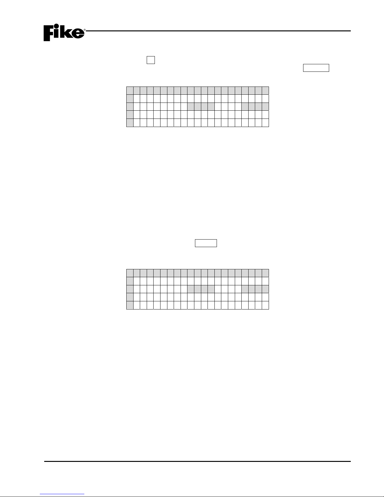
3.0 GETTING STARTED
3.2.1 HOW TO LOG ONTO THE SYSTEM
To log onto the system, press the F4 function key from the Top Level Menu. The Password screen, as
shown in Exhibit 3-3 will be displayed. After entering a successful password, press the ESCAPE key to
return to the Top Level menu.
1 2 3 4 5 6 7 8 9 0 1 2 3 4 5 6 7 8 9 0
A E N T E R P A S S W O R D
B X X X X<---X X X X
C ACCESS : DEN I ED
D CODE : XXXX
Exhibit 3-3: Password Entry Screen
• Row B - Allows entry of a 4 digit password. Use the ◄► navigation buttons to move the cursor to the
appropriate field and the +/- buttons (cycles through 0-9) to enter a password.
• Row C - Displays the access level (Denied, Level 2 (A-H), Sys Admin, Factory) allowed with the
password that has been entered.
• Row D - Random 4 digit-code that changes periodically. Used by the factory to gain access to the
system if the Administrator password has been forgotten.
3.2.2 CHANGING THE SYSTEM ADMINISTRATOR PASSWORD
After entering a successful Administrator level password, you can change the default administrator password
by changing the 4-digit number on the far right of Row B, as shown in Exhibit 3-4. Use the ◄► navigation
buttons to move the cursor under each field and the +/- buttons to enter the new password (cycles through 0-
9). After completing the password change, press the ENTER key to confirm the change. If the Administrator
password is changed and then forgotten, you must call Fike and provide the 4-digit CODE displayed on Row
D of the password entry screen.
1 2 3 4 5 6 7 8 9 0 1 2 3 4 5 6 7 8 9 0
A E N T E R P A S S W O R D
B _ _ _ _<---X X X X
C ACCESS : DEN I ED
D CODE : XXXX
Exhibit 3-4: Password Entry Screen
• Row B - Allows entry of a 4 digit password. Use the ◄► navigation buttons to move the cursor and
the +/- buttons (cycles through 0-9) to enter a password.
• Row C - Displays the access level (Denied, Level 2 (A-H), Sys Admin, Factory) allowed with the
password that has been entered.
• Row D - Random 4 digit-code that changes periodically. Used by the factory to gain access to the
system if the Administrator password has been forgotten.
CyberCat 254/1016 Programming Manual 3-3
P/N: 06-539 Rev 3, 08/2013

3.0 GETTING STARTED
3.3 CONFIGURING THE SYSTEM
There are two basic methods for configuring the CyberCat system: AUTOPROGRAM or ENGINEERED
CONFIGURE.
3.3.1 AUTOPROGRAM
This configuration method is used for small systems requiring typically no more than one zone of operation.
This method allows you to connect all unaddressed devices to the panels SLC circuits and by using panel’s
AUTO ADDRESSING function, each device is randomly addressed in the order that they are recognized by
the panel. The panel’s LEARN function is then used to upload the default configuration held by each device
into the panel. Each device (inputs and outputs) is assigned to Zone 1 by default. At this point, the panel
configuration menus can be used to make simple changes to the system/device configurations. For more
extensive configuration changes, you should use the C-Linx configuration software to create a configuration
template, make necessary changes, and upload the modified configuration back into the control panel.
LNote: The drawback to using the AUTOPROGRAMMING method is that the devices are randomly
addressed; therefore, you must document the actual location of each device during the functional testing
of the system. If any device was missed, you must manually add it into the configuration.
3.3.2 ENGINEERED CONFIGURE
This configuration method is used for larger more complex systems requiring multiple zones of operation. In
this arrangement, a Fire Alarm designer creates installation documents for the project that identifies the
required location and address of each addressable device. The installer then installs and addresses each
device according to the installation documents. The following sections outline the different methods that can
be used to address each device.
3-4 CyberCat 254/1016 Programming Manual
Rev 3, 08/2013 P/N: 06-539

3.0 GETTING STARTED
3.4 HOW TO ADDRESS A DEVICE
Each addressable device is shipped from the factory defaulted to Loop 0, Address 0. This address must be
changed to suit the project requirements. There are several different ways of assigning addresses to a field
device. A general description of each addressing method is described below. Any combination of these
methods can be used to successfully address the field devices to match your project requirements.
3.4.1 HOW TO AUTO ADDRESS FIELD DEVICES (AUTO A)
This method allows you to take all field devices straight out of the box and connect them to the panel’s
signaling line circuit (SLC) without addressing the devices first. The Auto Addressing (AUTO A) function
when activated, allows the panel to identify all new addressable devices (Loop 0, Address 0) connected to the
SLC circuit. As each new device is recognized by the panel, it is automatically assigned the next available
address.
To Auto Address devices:
1. Press the ESCAPE key until the CyberCat’s TOP LEVEL MENU is displayed.
2. Press the F4 key to enter the systems PASSWORD entry screen, and then enter a valid Level 3
password.
3. Press the ESCAPE key to return to the TOP LEVEL MENU.
4. Press the F1 key to enter the systems CONFIGURATION MENU 1, and then press the F6 key four times
until the CONFIGURATION MENU 5 screen is displayed.
5. Press the F2 key to enter the AUTO ADDRESSING screen.
1 2 3 4 5 6 7 8 9 0 1 2 3 4 5 6 7 8 9 0
A
A U T O ADDRES S I NG : O F F
B
S E L E C T L O O P S : 1 2 3 4
C
S E L E C T A D D R S : 0 0 1 → 0 5 0
D
P R E SS ENTE R TO STORE
Exhibit 3-5: Auto Address Screen
• Row A - This field allows you to turn the Auto Addressing feature ON/OFF. Use the ◄► arrow keys
to move cursor to the field; then use the +/- keys to toggle the field (ON/OFF).
• Row B - This field allows you to select which addressable loops will be affected when Auto
Addressing is turned ON. Use the ◄► arrow keys to move cursor to the field; then use the +/- keys
to toggle the field.
• Row C - This field allows you to select the address range that you would like to auto address. Use
the ◄► arrow keys to move cursor to the field; then use the +/- keys to toggle the field.
• Row D - When you have the address range that you would like to have auto addressed, press the
ENTER key. Devices will NOT be addressed until it is added to the loop (NEW DEVICE record
identified) and the panel is reset.
CyberCat 254/1016 Programming Manual 3-5
P/N: 06-539 Rev 3, 08/2013

3.0 GETTING STARTED
3.4.2 HOW TO USE THE PANEL’S DEVICE ADDRESS FUNCTION TO ADDRESS A DEVICE
This method allows you to take a field device straight out of the box and connect it to the panel’s signaling line
circuit (SLC) to be addressed. The Device Address (DEV ADR) function when activated, allows the panel to
automatically assign an address to each new device as it is connected to the panel’s signaling line circuit
(SLC).
To Address devices:
1. Press the ESCAPE key until the CyberCat’s TOP LEVEL MENU is displayed.
2. Press the F5 key to enter the systems MAINTENANCE MENU.
3. Press the F2 key to enter the DEVICE ADDRESS screen (DEV ADR).
1 2 3 4 5 6 7 8 9 0 1 2 3 4 5 6 7 8 9 0
A S E LEC T ADDRESS
B L O O P : 1 ADDRESS : 0 0 1
C
D P R E S S E N T E R T O S T A R T
Exhibit 3-6: Device Address Screen
• Row B – Use these fields to set the loop (1 – 5) and starting address number (1 – 254) to be
assigned to the device. Use the ◄►arrow keys to move the cursor under the Loop and Address
fields; then use the +/- keys to increment/decrement the fields.
• Row D - Press the ENTER key to start the automatic address function.
4. Once the chosen loop and address is set, press the ENTER key to start the automatic address function.
The following Connect Device screen will be displayed.
1 2 3 4 5 6 7 8 9 0 1 2 3 4 5 6 7 8 9 0
A C O N N E C T D E V I C E T O
B A D D R E S S A B L E L O O P
C P R E S S E N T E R W H E N
D C O M P L E T E
Exhibit 3-7: Connect Device Screen
• Attach sensors to the integral base on the programmer.
• Attach modules to the programmer using the supplied wire leads (Red wire to Loop positive
connection; Black wire to Loop negative connection).
3-6 CyberCat 254/1016 Programming Manual
Rev 3, 08/2013 P/N: 06-539

3.0 GETTING STARTED
Once the programmer recognizes that a new device has been attached, a NEW DEVICE message will be
briefly displayed on Rows C & D:
1 2 3 4 5 6 7 8 9 0 1 2 3 4 5 6 7 8 9 0
A
C O N N E C T D E V I C E T O
B
A D D R E S S A B L E L O O P
C
*NEW DEVICE*
D
*DETECT ED*
Exhibit 3-8: New Device Detected Screen
LNote: The programmer requires the NEW DEVICE record from the device before it will recognize it. If the
device was already installed prior to accessing this screen, you must REMOVE and RE-INSTALL the
device for the Hand Held Programmer to receive the NEW DEVICE record.
5. Once the programmer has detected the New Device, Press the ENTER key to assign the new loop and
address to the attached device:
1 2 3 4 5 6 7 8 9 0 1 2 3 4 5 6 7 8 9 0
A C O N N E C T D E V I C E T O
B A D D R E S S A B L E L O O P
C P R E S S E N T E R W H E N
D C O M P L E T E
Exhibit 3-9: Connect Device Screen
If the address change was successfully completed, the following screen will be displayed:
1 2 3 4 5 6 7 8 9 0 1 2 3 4 5 6 7 8 9 0
A L O O P : n ADDRESS : n n n
B D E V I CE ADDR CHANGE
C COMPLETED
D E N T E R F O R N E X T D E V I C
Exhibit 3-10: Address Change Completed Screen
You are now ready to program the next sequential loop-address (the panel will auto-increment the address
number after each successful address write), press the ENTER key to return to step #3.
If the address did NOT successfully change, the following screen will be displayed:
1 2 3 4 5 6 7 8 9 0 1 2 3 4 5 6 7 8 9 0
A L O OP : 1 ADDRE SS : NNN
B D E V I CE ADDR CHANGE
C F A I L E D
D E N T E R F O R N E X T D E V I C
Exhibit 3-11: Address Change Failed Screen
Remove/disconnect the device being addressed from the programmer and press the ENTER key to return to
step #3 and repeat the process.
6. If complete, remove/disconnect all devices and power down the Hand Held Programmer.
CyberCat 254/1016 Programming Manual 3-7
P/N: 06-539 Rev 3, 08/2013

3.0 GETTING STARTED
3.4.3 HOW TO ADDRESS DEVICES WITH THE IR TOOL (P/N 55-051)
The IR tool is a hand-held remote control that is designed to communicate with the CyberCat addressable
devices via infrared signals. The tool gives you the ability to assign an address to a new device that is
connected to the panel’s signaling line circuit (SLC).
By default the IR communication is disabled on the CyberCat loops. The user must first enable the IR
communication to allow the tool the ability to communicate with the devices connected to the SLC. Enabling
the IR communication requires a Level 3 password (Distributor Level).
To turn on IR Communication:
1. Press the ESCAPE key until the CyberCat’s TOP LEVEL MENU is displayed.
2. Press the F6 key to display the IR COMMUNICATION screen (IR COMM).
1 2 3 4 5 6 7 8 9 0 1 2 3 4 5 6 7 8 9 0
A I R C O M M U N I C A T I O N
B L OO P 1 : D I SLOOP2:D I S
C L OO P 3 : D I SLOOP4:D I S
D
Exhibit 3-12: IR Communication Screen
• Rows B & C - Displays the IR Communication status by loop. Enable only one loop at a time. Use
the ◄► keys to move the cursor to the field; then use the +/- keys to toggle the ENAble/DISable
status of the loop. Disable the IR when complete or Reset the control panel (turns IR back OFF).
3-8 CyberCat 254/1016 Programming Manual
Rev 3, 08/2013 P/N: 06-539

3.0 GETTING STARTED
The IR Tool, as shown in Exhibit 3-13, has many uses with the CyberCat addressable devices. Consult the
individual Installation and Maintenance Instructions (P/N 55-051) for a complete description of its operation.
To address a device using the IR Tool:
1. Press the PWR key on the IR tool. The main menu will be displayed.
2. Aim the IR tool at the device to be addressed and press the SELECT key. The device must be selected
before communication is enabled. When a device is selected, the LED on the device will change to a
blinking green pattern.
LNote: There must be a clear line of sight between the IR tool and the device it is communicating with.
3. The display will indicate ‘1. WRITE LOOP/ADR’. Press the ENTER key.
4. Use the number buttons to type in the desired Loop and Address number for the device. (Loops = 001004; Addresses = 001-254)
5. Point the IR tool at the device being addressed and press the ENTER key. If the address is accepted,
the display will indicate ‘OK NEW – Addr. SET.
6. If addressing devices sequentially, press the
× key to increment to the next address number.
7. Press the SELECT button to select the next device.
8. Press ENTER to save the incremented address to the selected device.
SELECT KEY
SCROLL UP KEY
ESCA PE KEY
POWER BUTTON
132
456
789
0
PWR
DESELECT KEY
SCROL L DOWN KEY
ENTER KEY
CyberCat 254/1016 Programming Manual 3-9
P/N: 06-539 Rev 3, 08/2013
Exhibit 3-13: IR Communication Tool

3.0 GETTING STARTED
3.4.4 HOW TO ADDRESS DEVICES WITH THE HAND-HELD PROGRAMMER (P/N 10-2648)
The Hand-Held programmer contains the same operating code as the CyberCat and can be used to assign
an address to a new addressable device. Refer to Fike document 06-390, “Hand-Held Programmer
Operating Instructions” for a complete description of the programmer’s functions and operations.
To address a device using the Hand-Held Programmer:
2. Turn on the Hand-Held programmer. The following Loop Start-up screen will be displayed for several
seconds. Do not make any changes to this screen.
1 2 3 4 5 6 7 8 9 0 1 2 3 4 5 6 7 8 9 0
A S E LEC T ADDRESS
B L O O P : 1 ADDRESS : 0 0 1
C W A I T F O R L O O P S T A R T :
D > > > > >>>>>>>>>>>>>>>>
Exhibit 3-14: Loop Start Screen
3. Upon completion of the loop start-up, the following Device Address screen will be displayed:
1 2 3 4 5 6 7 8 9 0 1 2 3 4 5 6 7 8 9 0
A S E LEC T ADDRESS
B L O O P : 1 ADDRESS : 0 0 1
C
D P R E S S E N T E R T O S T A R T
Exhibit 3-15: Device Address Screen
• Row B – Use these fields to set the loop (1 – 5) and starting address number (1 – 254) to be
assigned to the device. Use the ◄►arrow keys to move the cursor under the Loop and Address
fields; then use the +/- keys to increment/decrement the fields.
4. Once the chosen loop and address is set, press the ENTER key to start the automatic address function.
The following Connect Device screen will be displayed:
1 2 3 4 5 6 7 8 9 0 1 2 3 4 5 6 7 8 9 0
A C O N N E C T D E V I C E T O
B A D D R E S S A B L E L O O P
C P R E S S E N T E R W H E N
D C O M P L E T E
Exhibit 3-16: Connect Device Screen
• Attach sensors to the integral base on the programmer.
• Attach modules to the programmer using the supplied wire leads (Red wire to Loop positive
connection; Black wire to Loop negative connection).
3-10 CyberCat 254/1016 Programming Manual
Rev 3, 08/2013 P/N: 06-539

3.0 GETTING STARTED
Once the programmer recognizes that a new device has been attached, a NEW DEVICE message will be
briefly displayed on Rows C & D:
1 2 3 4 5 6 7 8 9 0 1 2 3 4 5 6 7 8 9 0
A
C O N N E C T D E V I C E T O
B
A D D R E S S A B L E L O O P
C
*NEW DEVICE*
D
*DETECT ED*
Exhibit 3-17: New Device Detected Screen
LNote: The programmer requires the NEW DEVICE record from the device before it will recognize it. If the
device was already installed prior to accessing this screen, you must REMOVE and RE-INSTALL the
device for the Hand Held Programmer to receive the NEW DEVICE record.
5. Once the programmer has detected the New Device, Press the ENTER key to assign the new loop and
address to the attached device:
1 2 3 4 5 6 7 8 9 0 1 2 3 4 5 6 7 8 9 0
A C O N N E C T D E V I C E T O
B A D D R E S S A B L E L O O P
C P R E S S E N T E R W H E N
D C O M P L E T E
Exhibit 3-18: Connect Device Screen
If the address change was successfully completed, the following screen will be displayed:
1 2 3 4 5 6 7 8 9 0 1 2 3 4 5 6 7 8 9 0
A L O O P : n ADDRESS : n n n
B D E V I CE ADDR CHANGE
C COMPLETED
D E N T E R F O R N E X T D E V I C
Exhibit 3-19: Address Change Completed Screen
You are now ready to program the next sequential loop-address (the panel will auto-increment the address
number after each successful address write), press the ENTER key to return to step #2.
If the address did NOT successfully change, the following screen will be displayed:
1 2 3 4 5 6 7 8 9 0 1 2 3 4 5 6 7 8 9 0
A L O OP : 1 ADDRE SS : NNN
B D E V I CE ADDR CHANGE
C F A I L E D
D E N T E R F O R N E X T D E V I C
Exhibit 3-20: Address Change Failed Screen
Remove/disconnect the device being addressed from the programmer and press the ENTER key to return to
step #2 and repeat the process.
6. If complete, remove/disconnect all devices and power down the Hand Held Programmer.
CyberCat 254/1016 Programming Manual 3-11
P/N: 06-539 Rev 3, 08/2013

3.0 GETTING STARTED
3.4.5 HOW TO ADDRESS DEVICES USING C-LINX’S DEVICE ADDRESSING WIZARD
If you have already built a configuration file using the C-Linx configuration software; you can use the
programs Device Addressing Wizard found in the Diagnostics menu to address devices that are connected to
a CyberCat panel or Hand-Held programmer:
1. Use C-Linx to open your existing configuration or create the configuration for the panel.
2. Click on ‘Diagnostics’.
3. Select/click on ‘Device Addressing Wizard’. A window will appear, titled ‘Device Addressing Wizard’.
4. Click the pull-down menu where it displays ‘No Panel’ and select the configuration of the panel that you
wish use for addressing the devices (that configuration needs to be already loaded in C-Linx Project
Explorer).
5. It will display each device loop and address information in the panel area.
6. Click ‘Start Addressing’.
7. Connect the programming cable from the communication port on the computer to the panel or the Hand
Held Programmer when it instructs to connect the Serial Cable.
8. C-Linx will then request a password. Type in the 4 digit password.
9. The Status Message will display connection status. Connect the device to be addressed.
10. Once C-Linx receives the NEW DEVICE record from the device, it will highlight that TYPE of device in
step 1. It will display the type, serial number, and address in the Step 2 area. You need to click on the
appropriate box in Step 3 area of C-Linx. Either select ‘Overwrite current address in this device’ OR ‘Do
not address this device’. If there is no longer a device type in the list that matches the device type
connected, it will display Device not needed for this configuration, ’Skip Device’. Click ‘Skip Device’ to
continue to the next device.
11. If you selected ‘Overwrite current address in this device’ it will display ‘Storing New Device Address’ and
then it will remove that device loop-address from the list of available devices.
12. Click on ‘Stop Addressing’ and it will ask if you wish to save the session for you to come back at a later
time and pick up addressing where you left off.
3-12 CyberCat 254/1016 Programming Manual
Rev 3, 08/2013 P/N: 06-539

3.0 GETTING STARTED
3.4.6 HOW TO ADDRESS DEVICES USING C-LINX’S ASSIGN DEVICE ADDRESS FUNCTION
Use this software diagnostic for simple loop-address change when the panel configuration is not available.
1. Open C-Linx software.
2. Connect to panel.
3. Click on ‘Diagnostics’.
4. Select/click on ‘Assign Device Address’. A window will appear, titled ‘Assign Device Address’.
5. Click ‘Diagnostics’ AGAIN.
6. Click ‘Connect to Panel’.
7. Connect the communication cable on the computer to the computer jack on the panel or Hand Held
Programmer when it instructs to connect the Serial Cable.
8. C-Linx will then request a password. Type in the 4 digit password.
9. The Status Message will display connection status; it will then command the panel or Hand Held
Programmer to search for the devices attached. Once it resets the loop of device(s) it will report each
type of device with its loop number, address number and serial number information.
10. Select a specific row to modify, then change the loop number and/or address number in the bottom box.
Click ‘Change Address’ to send the device the new loop and address number.
11. Mark or label the device with the loop-address information.
12. Repeat for each device needed, then exit the Assign Device Address screen, unless you wish to do a
LEARN ALL DEVICES at this time. If you do, while ASSIGN DEVICE ADDRESS screen is open and all
devices still show on screen, click on Diagnostics again, and the click/select Reset Panel with Learn All.
If you do not wish to do a LEARN ALL DEVICES, skip step #12 and proceed to step #13
13. Close Assign Device address screen. If properly completed, all devices should now have valid
addresses.
LNote: This diagnostic is intended for full loop of devices that are already wired in the field.
CyberCat 254/1016 Programming Manual 3-13
P/N: 06-539 Rev 3, 08/2013

3.0 GETTING STARTED
Reserved for future use.
3-14 CyberCat 254/1016 Programming Manual
Rev 3, 08/2013 P/N: 06-539

4.0 CONFIGURATION MENU
4.1 CONFIGURATION MENU
The CyberCat’s configuration menus allow you to change certain operational settings of the main control
board, peripheral devices, attached modules and optional cards. For more detailed configuration of the
system, you must use Fike’s C-Linx configuration software.
The information presented in this section reflects the configuration options that are available for panels
equipped with firmware version 6.XX. It provides a description of the available configuration options and how
you can change the settings from the main controller/display unit. It is intended for those who have been
factory trained and authorized to program the CyberCat system. Refer to Appendix A for a breakdown of the
CyberCat’s menu structure.
The CyberCat’s configuration menus are password protected to prevent unauthorized access. To gain
access to the panels configuration menus, you must enter a valid Level 3 password. Entering a Level 2
password gives you the ability to view all of the panel’s current configuration settings, but restricts the settings
that you are able to change. See Section 3.2.1 for instructions on how to log onto the system.
4.2 CONFIGURATION MENU 1
From the Top Level Menu screen, press the F1 key to display the “Configuration Menu 1” screen, as shown
below:
1 2 3 4 5 6 7 8 9 0 1 2 3 4 5 6 7 8 9 0
A
C O N F I GURAT I ON MENU 1
B
F 1 - DEV I CE F4 - LEARN
C
F 2 - NAC F 5 - VO I CE
D
F 3 - S L C F 6 - M E N U 2
Exhibit 4-1: Configuration Menu 1
Press the corresponding function key to display the selected configuration screen:
F1 = Device Configuration Menu
F2 = NAC Configuration Menu
F3 = SLC Configuration Screen
F4 = Learn Screen
F5 = Voice Operation Screen
F6 = Configuration Menu 2
4.2.1 HOW TO CONFIGURE A FIELD DEVICE
The Device Configuration menu allows you to modify the operational parameters of the addressable devices
connected to the CyberCat’s signaling line circuits (SLC).
From the “Configuration Menu 1”, press the F1 key to display the “Device Configuration Menu” screen, as
shown below:
1 2 3 4 5 6 7 8 9 0 1 2 3 4 5 6 7 8 9 0
A
F 1 - A L A R M F E A T U R E S
B
C
F 3 - CONF I GURAT I ON CHK
D
Exhibit 4-2: Device Configuration Menu
Press the corresponding function key to display the selected configuration screen:
F1 = Device Alarm Features
F3 = Configuration Check screen
CyberCat 254/1016 Programming Manual 4-1
P/N: 06-539 Rev 3, 08/2013

4.0 CONFIGURATION MENU
4.2.1.1 HOW TO CHANGE A DEVICES ALARM FEATURES
After all SLC devices have been connected into the system, you can use the Alarm Features screen to make
basic configuration changes to each device.
From the “Device Configuration Menu” screen, press the F1 key to display the “Alarm Features” screen, as
shown below:
1 2 3 4 5 6 7 8 9 0 1 2 3 4 5 6 7 8 9 0
A
L - A D R : DEV I CE TYPE
B
F U N C : * F U N C T I O N - - - - N O
C
C U S T O M M E S S A G E
D
Z O N E : 0 0 0 0 0 0 0 0 0 0 0 0
Exhibit 4-3: Alarm Features Screen
• Row A (L-ADR) - Allows you to select the loop and address of a specific SLC device in order to
display its configuration parameters. Use the ◄► arrow keys to position the cursor under any of
the fields; then use the +/- keys to change to a different loop or address number.
When you select a device, the control panel displays information about the device. The screen does
not show all configuration options that are available for each device. In order to be able to view and
change all operating parameters for each device, you must use the C-Linx panel configuration
software. Refer to Fike document 06-448 “C-Linx User’s Guide” for additional configuration options.
• Row A (Device Type) - Changes to display the type of device found at the selected loop-address:
Photo Sensor, Dual Monitor, Ion Sensor, Conv Zone, Photo/Heat Sensor, Heat Sensor, Photo Duct
Det, Control Module, Relay Module, Monitor Module, Mini Module and Pullstation.
• Row B (FUNC) - Allows you to change the function of the selected device address (if applicable).
Use the ◄► arrow keys to position the cursor under the field; then use the +/- keys to change the
device function. The ability to change the function field is available only on certain device types.
• Row C - This range of fields allows you to enter a 20 character custom message for the selected
address. These fields can be edited using the ◄► arrow keys to position the cursor under any of
the fields; then use the +/- keys to cycle through all available ASCII characters.
• Row D - The functionality of the fields in this row changes depending upon the device type displayed
in Row A. The programming options available for each device type are described as follows.
I CAUTION
If you change any of the devices configuration settings, you
MUST press the ENTER button to successfully change the
configuration at the device. Wait for the asterisk (*) shown next
to the device function on Row B to go away prior to leaving the
screen. Exiting the screen with the asterisk still visible will cause
the selected device to be partially configured which will result in
improper operation.
4-2 CyberCat 254/1016 Programming Manual
Rev 3, 08/2013 P/N: 06-539

4.0 CONFIGURATION MENU
A. HOW TO MODIFY A SENSOR
The default programming options for a sample photoelectric smoke sensor are shown below:
1 2 3 4 5 6 7 8 9 0 1 2 3 4 5 6 7 8 9 0
A
1 - 0 0 1:P HOTO SENSOR
B
F U N C : * - - - - - - - - - - - - - -
C
C U S T O M M E S S A G E 1 - 0 0 1
D
Z O N E : 0 0 1 0 0 0 0 0 0 0 0 0
Exhibit 4-4: Alarm Features Screen
(Sensors and Detectors)
• Row A - Displays the loop and address of the selected SLC device.
• Row B - Displays the function of the device. Not editable for this device type.
• Row C - Displays the 20 character custom message for the selected address. Use the ◄► arrow
keys to position the cursor under any of the fields; then use the +/- keys to cycle through all
available ASCII characters.
• Row D - The fields in this row display the zone settings for the selected device address in Row A.
Use the ◄► arrow keys to position the cursor under one of the zone number fields (000); then use
the +/- keys to change the zone number. To add multiple zones, move the cursor to the 2nd-4th
zone number fields; then use the +/- keys to change or add the zone number.
LNote: These programming options are typical for Photo Sensor, Ion Sensor, Photo/Heat Sensor,
Heat Sensor and Photo Duct Detector.
B. HOW TO MODIFY A CONTROL OR RELAY MODULE
The default programming options for a sample control module are shown below:
1 2 3 4 5 6 7 8 9 0 1 2 3 4 5 6 7 8 9 0
A
1 - 0 0 1:C ONTROL MODULE
B
F U N C : * - - - - - - - - - - - - - -
C
C U S T O M M E S S A G E 1 - 0 0 1
D
- - - -:0 0 0 0 0 0 0 0 0P:*
Exhibit 4-5: Alarm Features Screen
(Control Module)
• Row A - Displays the loop and address of the selected SLC device.
• Row B - This field allows you to switch the function of the control module between ANY OF 3
ZONES, ALL OF 3 ZONES, SELECT DEVICE or ROW ANDING. Each function is described as
follows. Use the ◄► arrow keys to position the cursor under the field; then use the +/- keys to
change the device function.
• Row C - Displays the 20 character custom message for the selected address. Use the ◄► arrow
keys to position the cursor under any of the fields; then use the +/- keys to cycle through all
available ASCII characters.
• Row D - The fields in this row change depending upon the device function displayed in Row B. The
programming options available for each device function are described as follows.
LNote: These programming options are typical for both the control and relay modules.
CyberCat 254/1016 Programming Manual 4-3
P/N: 06-539 Rev 3, 08/2013

4.0 CONFIGURATION MENU
MODULE FUNCTIONALITY - ANY OF 3 ZONES
This function setting requires a state broadcast matching the activation state shown in Row D to come from at
least one of the three specified zones before the control modules output will activate.
1 2 3 4 5 6 7 8 9 0 1 2 3 4 5 6 7 8 9 0
A
1 - 0 0 1 : C O N T R O L M O D U L E
B
F U N C : * A N Y O F 3 Z O N E S
C
C U S T O M M E S S A G E 1 - 0 0 1
D
A L R M : 0 0 0 0 0 0 0 0 0P:*
Exhibit 4-6: Any of 3 Zones Function Screen
• Row D - Provides access to the first row of the modules output priority control table. To cycle
through the possible states of activation, use the ◄► arrow keys to position the cursor under the
ALRM field; then use the +/- keys to change the activation state:
AVON = Alarm Verification On
LTRB = Low Power Trouble
STRB = Short Circuit Trouble
OTRB = Open Circuit Trouble
MTRB = Maintenance Trouble
TSTA = Test Alarm
TRBL = Trouble
PROC = Process
PRA2 = Pre-Alarm 2
PRA1 = Pre-Alarm 1
SUPV = Supervisory
SUMA = Summing Alarm
ALRM = Alarm
ALRT = Voice Alert
EVAC = Voice Evacuation
PAGE = Voice Page
MSSA = Mass Notification All Zones
MSSZ = Mass Notification by Zone
2ALL = Page to Alert, Page to EVAC, Page All, Page R&R All
ZDIS = Zone Disable
The 000 fields allow you to set zone settings for the selected device address in Row A. Use the ◄►
arrow keys to position the cursor under one of the zone number fields (000); then use the +/- keys to
change the zone number. To add multiple zones, move the cursor to the 2nd-3rd zone number
fields; then use the +/- keys to change or add the zone number.
P:X allows you to select the activation pattern for the modules output, where X signifies:
0 = OFF F = FAST
1 = ON T = TEMPORAL
S = SLOW W = WALKTEST)
Use the ◄► arrow keys to position the cursor under pattern field; then use the +/- keys to change
the activation pattern.
4-4 CyberCat 254/1016 Programming Manual
Rev 3, 08/2013 P/N: 06-539

4.0 CONFIGURATION MENU
MODULE FUNCTIONALITY - ALL OF 3 ZONES
This function setting requires a state broadcast matching the activation state shown in Row D to come from all
of the three specified zones before the control modules output will activate.
1 2 3 4 5 6 7 8 9 0 1 2 3 4 5 6 7 8 9 0
A
1 - 0 0 1:C ONTROL MODULE
B
F U N C : * A L L O F 3 Z O N E S
C
C U S T O M M E S S A G E 1 - 0 0 1
D
A L R M: 0 0 0 0 0 0 0 0 0P:*
Exhibit 4-7: All of 3 Zones Function Screen
• Row D - Provides access to the first row of the modules output priority control table. To cycle
through the possible states of activation, use the ◄► arrow keys to position the cursor under the
ALRM field; then use the +/- keys to change the activation state:
AVON = Alarm Verification On
LTRB = Low Power Trouble
STRB = Short Circuit Trouble
OTRB = Open Circuit Trouble
MTRB = Maintenance Trouble
TSTA = Test Alarm
TRBL = Trouble
PROC = Process
PRA2 = Pre-Alarm 2
PRA1 = Pre-Alarm 1
SUPV = Supervisory
SUMA = Summing Alarm
ALRM = Alarm
ALRT = Voice Alert
EVAC = Voice Evacuation
PAGE = Voice Page
MSSA = Mass Notification All Zones
MSSZ = Mass Notification by Zone
2ALL = Page to Alert, Page to EVAC, Page All, Page R&R All
ZDIS = Zone Disable
The 000 fields allow you to set zone settings for the selected device address in Row A. Use the
◄► arrow keys to position the cursor under one of the zone number fields (000); then use the +/-
keys to change the zone number. To add multiple zones, move the cursor to the 2nd-3rd zone
number fields; then use the +/- keys to change or add the zone number.
P:X allows you to select the activation pattern for the modules output, where X signifies:
0 = OFF F = FAST
1 = ON T = TEMPORAL
S = SLOW W = WALKTEST)
Use the ◄► arrow keys to position the cursor under pattern field; then use the +/- keys to change
the activation pattern.
CyberCat 254/1016 Programming Manual 4-5
P/N: 06-539 Rev 3, 08/2013

4.0 CONFIGURATION MENU
MODULE FUNCTIONALITY - SELECT DEVICE
This function setting requires a state broadcast matching the activation state to come from the selected
device loop-address shown in Row A before the control modules output will activate.
1 2 3 4 5 6 7 8 9 0 1 2 3 4 5 6 7 8 9 0
A
1 - 0 0 1 : C O N T R O L M O D U L E
B
F U N C : * S E L E C T D E V I C E
C
C U S T O M M E S S A G E 1 - 0 0 1
D
L O O P : 0 ADR : 0 0 1P:*
Exhibit 4-8: Select Device Function Screen
• Row D -These fields allow you to select the loop and address of a specific SLC device that will
activate the selected control module. Use the ◄► arrow keys to position the cursor under any of
the fields; then use the +/- keys to change to a different loop or address number.
P:X allows you to select the activation pattern for the modules output, where X signifies:
0 = OFF F = FAST
1 = ON T = TEMPORAL
S = SLOW W = WALKTEST)
Use the ◄► arrow keys to position the cursor under pattern field; then use the +/- keys to change
the activation pattern.
MODULE FUNCTIONALITY - ROW ANDING
This function setting requires all of the priority rows specified in Row D to become active before the control
modules output will activate.
1 2 3 4 5 6 7 8 9 0 1 2 3 4 5 6 7 8 9 0
A
1 - 0 0 1 : C O N T R O L M O D U L E
B
F U N C : * R O W A N D I N G
C
C U S T O M M E S S A G E 1 - 0 0 1
D
R : 0 0 0 0 0 0 0 0P:*
Exhibit 4-9: Row Anding Function Screen
• Row D - These fields allow you to select the priority rows that must be active before the output of the
selected control module activates. Use the ◄► arrow keys to position the cursor under any of the
fields; then use the +/- keys to set the priority row.
P:X allows you to select the activation pattern for the modules output, where X signifies:
0 = OFF F = FAST
1 = ON T = TEMPORAL
S = SLOW W = WALKTEST)
Use the ◄► arrow keys to position the cursor under pattern field; then use the +/- keys to change
the activation pattern.
4-6 CyberCat 254/1016 Programming Manual
Rev 3, 08/2013 P/N: 06-539

4.0 CONFIGURATION MENU
C. HOW TO MODIFY A MONITOR MODULE
The default programming options for a sample monitor module are shown below:
1 2 3 4 5 6 7 8 9 0 1 2 3 4 5 6 7 8 9 0
A
1 - 0 0 1 : M ON I TOR MODUL E
B
F U N C : * - - - - - - - - - - - - N O
C
C U S T O M M E S S A G E 1 - 0 0 1
D
Z O N E : 0 0 0 0 0 0 0 0 0 0 0 0
Exhibit 4-10: Alarm Features Screen (Monitor Module)
• Row A - Displays the loop and address of the selected SLC device.
• Row B - This field allows you to select the input function for the selected device. To cycle through
the possible input functions, use the ◄► arrow keys to position the cursor under the function field;
then use the +/- keys to change the function:
Pre-Alarm I Supervisory AHU Fire Key
Pre-Alarm 2 Reset MNS Message
Man Alarm Silence Voice Messg
Waterflow Acknowledge Voice EVAC
Pre-Disch
Man Release
Abort
1
Drill Voice Alert
1
1
Zone Disable
PAS Inhibit
Process Watermist
Trouble Fan Restart
Detection Smoke Control Feedback
Man. Alarm 2
nd
Stage
• Row B - The last two fields on this row allow you to select whether the module will be monitoring
Normally Open (NO) or Normally Closed (NC) contacts. Not all input functions provide the option of
NO/NC contacts as follows:
Pre-Alarm I NO/NC Supervisory NO AHU Fire Key NO
Pre-Alarm 2 NO/NC Reset NO MNS Message NO
Man Alarm NO Silence NO/NC Voice Messg NO
Waterflow NO Acknowledge NO/NC Voice EVAC NO
Pre-Disch
Man Release
Abort
1
1
NO Drill NO/NC Voice Alert NO
1
NO Zone Disable NO/NC
NO PAS Inhibit NO/NC
Process NO/NC Watermist NO
Trouble NO/NC Fan Restart NO/NC
Detection NO Smoke Control NO
Man Alrm. 2
nd
NO
• Row C - Displays the 20 character custom message for the selected address. Use the ◄► arrow
keys to position the cursor under any of the fields; then use the +/- keys to cycle through all
available ASCII characters.
• Row D - The 000 fields allow you to set zone settings for the selected device address in Row A.
Use the ◄► arrow keys to position the cursor under one of the zone number fields (000); then use
the +/- keys to change the zone number. To add multiple zones, use the ◄► arrow keys to move
the cursor to the 2nd-3rd zone number fields; then use the +/- keys to change or add the zone
number.
LNote: These programming options are typical for the mini and dual input monitor modules as well.
1
Available on Cheetah Xi panels only.
CyberCat 254/1016 Programming Manual 4-7
P/N: 06-539 Rev 3, 08/2013

4.0 CONFIGURATION MENU
D. HOW TO MODIFY A PULL STATION
The default programming options for a sample pull station module are shown below:
1 2 3 4 5 6 7 8 9 0 1 2 3 4 5 6 7 8 9 0
A
1 - 0 0 1 : P U L L S T A T I O N
B
F U N C : * M A N A L A R M
C
C U S T O M M E S S A G E 1 - 0 0 1
D
Z O N E : 0 0 0 0 0 0 0 0 0 0 0 0
Exhibit 4-11: Alarm Features Screen
(Pull Station Module)
• Row A - Displays the loop and address of the selected SLC device.
• Row B - This field is defaulted to MANual ALARM and cannot be changed.
• Row C - Displays the 20 character custom message for the selected address. Use the ◄► arrow
keys to position the cursor under any of the fields; then use the +/- keys to cycle through all
available ASCII characters.
• Row D The 000 fields allow you to set zone settings for the selected device address in Row A. Use
the ◄► arrow keys to position the cursor under one of the zone number fields (000); then use the
+/- keys to change the zone number. To add multiple zones, move the cursor to the 2nd-3rd zone
number fields; then use the +/- keys to change or add the zone number.
E. HOW TO DELETE A DEVICE FROM THE SYSTEM CONFIGURATION
You can delete a device from the system configuration by pressing the F1 key while viewing the device
configuration. The panel will display the “Delete Device” screen, as shown below:
1 2 3 4 5 6 7 8 9 0 1 2 3 4 5 6 7 8 9 0
A
L - A D R : DEV TYPE
B
P RESS ENTER TO
C
D ELETE DEV I CE
D
Exhibit 4-12: Delete Device Screen
• Row A - This field allows you to select the loop and address of a specific SLC device to be deleted.
Use the ◄► arrow keys to position the cursor under any of these fields; then use the +/- keys to
change to a different loop number or address number. Device information for the address shown is
then displayed (if connected). The device type field is not editable, but will change for each device
type found on the loop. Press the ENTER key to remove the device address from the list of devices
to supervise.
4-8 CyberCat 254/1016 Programming Manual
Rev 3, 08/2013 P/N: 06-539

4.0 CONFIGURATION MENU
F. HOW TO READ, WRITE, ENABLE OR, DISABLE A DEVICE
From the “Alarm Features” screen, press the F2 key to access the “Read/Write/Enable/Disable Device”
screen, as shown below:
1 2 3 4 5 6 7 8 9 0 1 2 3 4 5 6 7 8 9 0
A
L - A D R: DEV TYPE
B
PRESS ENTER TO
C
R E A D D E V I C E C O N F I G
D
Exhibit 4-13: Read/Write/Enable/Disable Screen
• Row A - This field allows you to select the Loop and Address of a specific SLC device to read its
configuration. Use the ◄► arrow keys to position the cursor under any of the L-ADR fields; then
use the +/- keys to change to a different loop number or address number. Device information for the
address shown is then displayed (if connected). The device type field is not editable, but will change
for each device type found on the loop.
• Row C - This field allows you to select to READ, WRITE, ENABLE or DISABLE the selected device
address. Use the ◄► arrow keys to position the cursor under field; then use the +/- keys to toggle
the field value. Press the ENTER key to perform the desired function.
READ - Will take a copy of the configuration that the device holds and send it to the panel.
Read must be used prior to running a configuration check when any changes are made to the
devices alarm features.
WRITE - Will take the copy of the configuration that the panel holds for the device and send it
to the device.
ENABLE/DISABLE - Lets you Enable/Disable programmed SLC devices (i.e., modules,
detectors, pull stations, etc.).
Disable - causes the panel to copy and store in the panel the current configuration from the
device. The panel then reconfigures the “Output Control” for the selected device to be
BLANK and sends this configuration to the device rendering it non-operational.
Enable – causes the panel to send the device enabled configuration stored in the panel to the
selected device.
• Row D - Displays the status of process after ENTER key is pressed. Wait until process is
completed prior to exiting this screen.
iCAUTION
Do not perform a DEVICE READ or LEARN ALL with devices disabled
on the system. Doing so will cause the disabled configuration stored in
the device(s) to be saved in the panel, rendering the panel’s enable
command useless. At this point, you must use C-Linx to download the
original configuration to the panel to re-enable the device.
CyberCat 254/1016 Programming Manual 4-9
P/N: 06-539 Rev 3, 08/2013

4.0 CONFIGURATION MENU
G. HOW TO SET THE AHU RELAY RE-START DELAY
Each addressable relay assigned to AHU shutdown, can be configured with a time delay that prevents the deactivation of the relay until the set time delay expires. Time delay will begin only upon activation of an AHU
restart switch. This feature allows the startup of AHU’s to be staggered
From the “Alarm Features” screen, select the address of the relay assigned to AHU shutdown; then, press the
F3 key to access the “AHU Re-start Delay” screen, as shown below:
1 2 3 4 5 6 7 8 9 0 1 2 3 4 5 6 7 8 9 0
A
A H U R E L A Y R E - S T A R T
B
D E L A Y : 0 3 3SECONDS
C
D
Exhibit 4-14: Addressable Relay AHU Re-start Delay Screen
• Row B - This field allows you to set a restart time delay (0 – 255 seconds). Use the ◄► arrow keys
to position the cursor under the field; then use the +/- keys to increment or decrement the number
value.
4-10 CyberCat 254/1016 Programming Manual
Rev 3, 08/2013 P/N: 06-539

4.0 CONFIGURATION MENU
4.2.1.2 HOW TO PERFORM A CONFIGURATION CHECK
The “Configuration Check” screen lets you compare the configuration stored in the specific SLC device to the
configuration stored in the control panel for that device.
From the “Device Configuration Menu”, press the F3 key to access the “Configuration Check” screen, as
shown below:
1 2 3 4 5 6 7 8 9 0 1 2 3 4 5 6 7 8 9 0
A
L - A D R: DEV TYPE
B
P A N E L : X X X D E V I C E : Z Z Z
C
P R E S S E N T E R T O S T A R T
D
C O M P A R I S O N 0 - 0 0 0
Exhibit 4-15: Configuration Check Screen
• Row A - This field allows you to select the Loop and Address of a specific SLC device to check its
configuration. Use the ◄► arrow keys to position the cursor under any of the L-ADR fields; then
use the +/- keys to change to a different loop number or address number. Device information for the
address shown is then displayed (if connected). The device type field is not editable, but will change
for each device type found on the loop.
• Row B - Displays the panel and device checksum values for the device selected.
• Row D - Indicates progress of configuration check.
4.2.2 HOW TO MODIFY THE PANEL’S NAC CIRCUITS
The NAC Configuration menu allows you to program the panel’s two on-board notification appliance circuits
(NAC #1 and NAC #2).
From the “Configuration Menu 1” screen, press the F2 key to access the “NAC Configuration” menu, as
shown below:
1 2 3 4 5 6 7 8 9 0 1 2 3 4 5 6 7 8 9 0
A
NAC MENU
B
F 1 - NAC FUNCT I ONS
C
F 2 - NAC ZONE ASS I GNS
D
F 3 - P R O T O C O L
Exhibit 4-16: NAC Configuration Menu
Press the corresponding function key to display the selected configuration screen:
F1 = NAC Functions Screen
F2 = NAC Zone Assignment Screen
F3 = NAC Synchronization Protocol Screen
CyberCat 254/1016 Programming Manual 4-11
P/N: 06-539 Rev 3, 08/2013

4.0 CONFIGURATION MENU
4.2.2.1 HOW TO MODIFY NAC FUNCTIONS
The NAC Functions screen allows you to set the operational parameters of the two on-board NACs.
From the “NAC Menu” screen, press the F1 key to access the “NAC functions” screen, as shown below:
1 2 3 4 5 6 7 8 9 0 1 2 3 4 5 6 7 8 9 0
A
N A C # 1 : E N A B L E D
B
S T A T E : S T A T E
C
P R O T O C O L : C O N S T A N T
D
S I : N D R : NWLK:NWF:N
Exhibit 4-17: NAC Functions Screen
• Row A (NAC#) - This field allows you to select the NAC circuit to configure (NAC 1 or NAC 2). Use
the ◄► arrow keys to position the cursor under the field; then use the +/- keys to
increment/decrement the field.
• Row A (ENABLED) - This field allows you to set the Enabled/Disabled status of the on-board
notification appliance circuits 1 & 2 (P10 & P11). Use the ◄► arrow keys to move cursor under the
Enabled/Disabled field; then use the +/- keys to toggle the field.
LNote: If either NAC circuit is disabled, the panel will annunciate both a Trouble and Supervisory
condition until the circuit(s) is enabled.
• Row B (State) - This field allows you to set the operating state for the NAC circuit displayed in Row
A. Use the ◄► arrow keys to move the cursor to Row B; then use the +/- keys to change the State
to the desired operation (i.e., Alarm, Pre Alarm 1, Pre Alarm 2, Supervisory, Trouble and Process).
• Row C (Protocol) - This field allows you to select whether the NAC circuit displayed in Row A will
use the NAC protocol set for the panel (see 4.2.2.3) or will activate constant. Use the ◄► arrow
keys to move the cursor to Row C; then use the +/- keys to change to the desired protocol.
LNote: Both NAC 1 and NAC 2 must be set to the same protocol unless one of them is set to No
Sync Protocol.
LNote: If a chime code is assigned to any zone, Row C will display ‘CHIME CODE’ by default and
can not be changed. See section 4.3.5.1 for complete description of Chime Code functionality.
• Row D - These fields allow you to set the Silenceable, Drill, Walktest, and Waterflow Enabled
(Y)/Disabled (N) status for the NAC circuit displayed in Row A.
SILENCEABLE (SI:) - field determines whether or not the selected NAC circuit will turn off
when the panel’s SILENCE button is pressed.
DRILL (DR:) - field determines whether or not the selected NAC circuit will turn on when the
panel’s DRILL button is pressed.
WALKTEST (WLK:) - field determines whether or not the selected NAC circuit will turn on
when the panel receives a Walktest Alarm from any one of the configured zones.
WATERFLOW (WF:) – field determines whether or not the selected NAC circuit will turn on
when the panel receives a Waterflow Alarm.
To change the Enabled/Disabled status of these fields, use the ◄► arrow keys to position cursor
under Y or N; then use the +/- keys to toggle the field.
4-12 CyberCat 254/1016 Programming Manual
Rev 3, 08/2013 P/N: 06-539

4.0 CONFIGURATION MENU
4.2.2.2 HOW TO SET NAC ZONE ASSIGNMENTS
The NAC Zone Assignment screen allows you to set which zones can activate the two on-board NACs.
From the “NAC Menu” screen, press the F2 key to access the “NAC Zone Assignment” screen, as shown
below:
1 2 3 4 5 6 7 8 9 0 1 2 3 4 5 6 7 8 9 0
A
N A C # 1: A N Y Z O N E
B
Z O N E RANGE : 0 0 1 - 020
C
1 2 3 4567890 1234567890
D
- - - - - - - - - - - - - - - - - - - -
Exhibit 4-18: NAC Zone Assignment Screen
• Row A (NAC#) – This field allows you to select the NAC circuit to configure (NAC 1 or NAC 2). Use
the ◄► arrow keys to position the cursor under the field; then use the +/- keys to
increment/decrement the field.
• Row A (Any Zone) – This field allows you to set whether the selected NAC circuit will activate on
ANY ZONE or MULTI ZONE. Use the ◄► arrow keys to move cursor to the field (ANY ZONE or
MULTI ZONE); then use the +/- keys to toggle the field.
LNote: The Any Zone option sets the selected NAC to activate on the configured state for any
zone. The Multi Zone option sets the selected NAC to activate on the configured state for any
zone selected in Row D.
• Row B - This field allows you to set the 20 zone range that is displayed in Rows C & D. Use the
◄► arrow keys to position the cursor under the zone range field; then use the +/- keys to
increment/decrement the group of 20 forward or backwards (Zones 001-254).
• Row C - These numbers act as placeholders and zone number indicators for the range of zones
selected on Row B.
• Row D - This range of fields allows you to set the zone assignment programming for the circuit
displayed in Row A if MULTIZONE is selected.
- = not programmed for this zone
Y = programmed for this zone
Use the ◄► arrow keys to position the cursor under the specific zone position; then use the +/- keys
to toggle the status.
LNote: The Any Zone option sets the selected NAC to activate on the configured state for any
zone. The Multi Zone option sets the selected NAC to activate on the configured state for any
zone selected in Row D.
CyberCat 254/1016 Programming Manual 4-13
P/N: 06-539 Rev 3, 08/2013

4.0 CONFIGURATION MENU
4.2.2.3 HOW TO SET NAC SYNC PROTOCOL
The NAC Protocol screen allows you to configure which synchronization protocol (i.e. Gentex or System
Sensor) will be used by the CyberCat’s notification appliance circuits (see 4.2.2.1). The selected sync
protocol applies to both NAC circuits.
From the “NAC Configuration Menu” screen, press the F3 key to access the “NAC Protocol” screen, as
shown below:
1 2 3 4 5 6 7 8 9 0 1 2 3 4 5 6 7 8 9 0
A
S E L E C T N A C P R O T O C O L
B
FOR PANEL:
C
G E N T E X
D
Exhibit 4-19: NAC Sync Protocol Screen
• Row C - This field allows you to set the SYNC protocol assignment for both notification appliance
circuits #1 & #2 (P8 & P9). Use +/- keys to toggle through the allowable Sync protocols (Gentex,
System Sensor).
4.2.3 HOW TO CHANGE SLC SUPERVISION
The SLC screen lets you change the supervision options of the available signaling line circuits.
From the “Configuration Menu 1” screen, press the F3 key to access the “SLC Configuration” screen, as
shown below:
1 2 3 4 5 6 7 8 9 0 1 2 3 4 5 6 7 8 9 0
A
A U X I L I A R Y L O O P S
B
M O D U L E P R E S E N T : N O
C
P A S : N O ACK : 1 5 0 0/0 0
D
L O O P W I R I N G S T Y L E : 4
Exhibit 4-20: SLC Configuration Screen
• Row B (SLM:) - This field allows you to turn on Supplemental Loop Module supervision (Yes/No). If
Yes is selected, the panel will begin supervising SLC 3 and 4 on the SLM. Use the +/- keys to
change the field (applies to CyberCat 1016 only).
I CAUTION
Having a SLM installed on the panel and not changing this field
to Yes could result in delayed SLC communication.
• Row C (PAS:) - This field allows you to turn on Positive Alarm Sequencing function on the detection
circuits (Yes/No). Use the +/- keys to change the field.
LNote: This feature is enabled or disabled for all sensors present on the panel. Refer to CyberCat
Operations Manual for full description of this feature.
• Row C (ACK:) - This field allows you to adjust the time frame in which the Alarm event must be
Acknowledged in order to initiate the panel’s Positive Alarm Sequence. The timer can be set
between 15 and 30 seconds. Use the ◄► arrow keys to move cursor under the field; then use the
+/- keys to increment or decrement the field.
4-14 CyberCat 254/1016 Programming Manual
Rev 3, 08/2013 P/N: 06-539

4.0 CONFIGURATION MENU
• Row C (00/00) - This field allows you to select specific voice message ID’s (primary/secondary) to
play during the PAS investigative period. Use the ◄► arrow keys to move cursor under the field;
then use the +/- keys to increment or decrement the field.
• Row D - This field allows you to set the Loop Wiring Style used for all 4 addressable loops (Style 4,
6 or 7). Use the +/- keys to change the field.
LNote: This is a system wide setting. All loops will be configured to use the selected wiring style.
If Style 6 or 7 is chosen and the loop is unused, jumpers must be installed to prevent open circuit
troubles.
4.2.3.1 HOW TO SET SLC COMMAND MODE FUNCTIONS
This screen allows you set how the CyberCat will respond to SLC devices that have been inadvertently locked
into the “Command Mode”.
From the “SLC Configuration” screen, press the F1 key to access the “SLC Command Mode” screen, as
shown below:
1 2 3 4 5 6 7 8 9 0 1 2 3 4 5 6 7 8 9 0
A
S T O RE TROUBL E FOR NO
B
N E W DEV I CE EVENT : N O
C
S E N D A U T O C O M M A N D
D
A T M I D N I G H T : N O
Exhibit 4-21: SLC Command Mode Screen
• Row B - This field allows you to set whether the panel will record a “DEVICE NOT READY” trouble
for all output devices (i.e. Control, Relay, and Release modules) that fail to report a “New Device”
message following a reset (YES/NO). If the “New Device” message is received, then “DEVICE
RETURN” will be recorded. The factory default condition is NO. Use the +/- keys to change the
field.
• Row D - This field allows you to set whether the panel will transmit an “AUTO” command onto the
loops each midnight if no alarms, troubles, supervisory, pre-alarm, drill, or process states are active
(YES/NO). The factory default condition is NO. Use the +/- keys to change the field.
LNote: This feature ensures that output devices will act correctly in the event a device has been
inadvertently placed in the ‘Command Mode’.
CyberCat 254/1016 Programming Manual 4-15
P/N: 06-539 Rev 3, 08/2013

4.0 CONFIGURATION MENU
4.2.4 HOW TO EXECUTE THE LEARN FUNCTION
The Learn function, when initiated, identifies all installed addressable devices connected to the panel’s
signaling line circuits (SLCs). The address, device type and serial number of each device is added to the
panel’s supervision list.
From the “Configuration Menu 1” screen, press the F4 key to access the “Learn” screen, as shown below:
1 2 3 4 5 6 7 8 9 0 1 2 3 4 5 6 7 8 9 0
A
S E L E C T R E S E T M O D E :
B
N O N E S E L E C T E D
C
P R E S S E N T E R T O S T A R T
D
P A NEL WI LL RESET
Exhibit 4-22: LEARN Screen
• Row B - This field allows you to set the LEARN mode to be used. Press +/- to change from None
Selected to Learn New Devices or Learn All Devices. A complete description of each mode is
described as follows.
LNote: Each addressable device connected to the SLC holds its own configuration. After the
LEARN function has been completed, you can modify the configuration as needed using either the
panel configuration menus or the C-Linx programming software.
4.2.4.1 LEARN New Devices Only
The Learn New Device Only option will identify only new addressable devices connected to a signaling line
circuit (SLC). New devices will be added to the panel’s device supervision list. New devices will operate with
the default configuration held by the device. If the device that has never been incorporated into a system, it
will contain the default configuration.
From the “Learn” screen, press +/- keys to change to Learn New Devices as shown below; then press the
Enter key:
1 2 3 4 5 6 7 8 9 0 1 2 3 4 5 6 7 8 9 0
A
S E L E C T R E S E T M O D E :
B
L E A R N N E W D E V I C E S
C
P R E S S E N T E R T O S T A R T
D
P A NEL WI LL RESET
Exhibit 4-23: LEARN NEW DEVICES Screen
The panel will reset and enter the Learn Mode:
1 2 3 4 5 6 7 8 9 0 1 2 3 4 5 6 7 8 9 0
A
L E A R N M O D E I S A C T I V E
B
W A I T TO COMPLETE >>
C
0 9 : 2 7 :47A 03 / 10 / 2009
D
A L : 0 0 0 SU:000 TR: 000
Exhibit 4-24: LEARN Mode Active Screen
The display keypad is locked while learn mode is Active. Panel will display “LEARN MODE COMPLETE”
when process ends.
4-16 CyberCat 254/1016 Programming Manual
Rev 3, 08/2013 P/N: 06-539

4.0 CONFIGURATION MENU
4.2.4.2 LEARN All devices
The Learn All Devices option erases the device supervision list stored in the CyberCat controller and creates
a new supervision list by identifying all addressable devices connected to a signaling line circuit (SLC). All
device addresses, serial numbers, and device type information will be learned. The configurations held by the
devices will NOT be altered (nor will the custom messages).
From the “Learn” screen, press +/- keys to change to Learn All Devices as shown below; then press the Enter
key:
1 2 3 4 5 6 7 8 9 0 1 2 3 4 5 6 7 8 9 0
A
S E L E C T R E S E T M O D E :
B
L E A R N A L L D E V I C E S
C
P R E S S E N T E R T O S T A R T
D
P ANEL WI LL RESET
Exhibit 4-25: LEARN ALL DEVICES Screen
The panel will reset and enter the Learn Mode:
1 2 3 4 5 6 7 8 9 0 1 2 3 4 5 6 7 8 9 0
A
L E A RN MODE I S ACT IV E
B
W A I T TO COMPLETE >>
C
0 9 : 27 :47A 03 / 10 / 2009
D
A L : 000 SU:000 TR:000
Exhibit 4-26: LEARN Mode Active Screen
The display keypad is locked while learn mode is Active. Panel will display “LEARN MODE COMPLETE”
when process ends.
I CAUTION
The Learn ALL method will delete and/or add supervision to
devices. Testing or review of the configuration should be
performed to ensure that all required devices are supervised.
CyberCat 254/1016 Programming Manual 4-17
P/N: 06-539 Rev 3, 08/2013

4.0 CONFIGURATION MENU
4.2.5 HOW TO ENABLE PANEL VOICE OPERATIONS
The “Voice Operation” screen allows you to setup the CyberCat system for voice operation.
From the “Configuration Menu 1” screen, press the F5 key to access the “Voice” screen, as shown below:
1 2 3 4 5 6 7 8 9 0 1 2 3 4 5 6 7 8 9 0
A
C H A N N E L M O D E : S I N G L E
B
S E Q U E N C E : S T A N D A R D
C
V O I C E O U T P U T S : O F F
D
F 1 - M N S R F 2 - P R I O R ITY
Exhibit 4-27: Voice Operations Screen
• Row A - This field allows you to select whether all system amplifiers will operate in single or dualchannel mode. Press +/- to change from Single to Dual channel mode. A complete description of
each mode is described as follows.
¾ Single Channel – each amplifier operates independently and is capable of playing a single
audio message in response to a system event.
¾ Dual Channel – two amplifiers are tied together to form a single dual-channel, 50 watt
amplifier with 8 speaker circuits. One amp is dedicated for EVAC operation and the other is
dedicated for Alert operation.
• Row B – This field allows you to set the city sequence code that will be used by the panel for voice
operation. Press +/- to change select proper city sequence code. A complete description of each
mode is described as follows.
¾ Standard – regular panel operation
¾ Boston – panel will operate following the requirements of the City of Boston.
¾ Chicago – panel will operate following the requirements of the City of Chicago.
¾ New York – panel will operate following the requirements of the City of New York.
¾ Special 1 or 2 – future use
LNote: Certain cities require the voice system to operate in a specific manner that differs from the
standard operation of the voice system.
• Row C – This field allows you to enable Eclipse messages that are unique to voice operation to be
transmitted onto the SLC for the purpose of activating control or relay modules for voice operation.
Press +/- to toggle the field from OFF (default) to ON.
• Row D – Press the F1 function button to access the mass notification reset screen or press the F2
function button to access the voice state priority screen.
4-18 CyberCat 254/1016 Programming Manual
Rev 3, 08/2013 P/N: 06-539

4.0 CONFIGURATION MENU
4.2.5.1 HOW TO SET MASS NOTIFICATION RESET TIMEOUT
The “MNS Reset” screen allows you to configure a timeout variable that will automatically issue a mass notify
reset command. Once enabled, the timeout starts upon activation of any voice action switches. The timer
restarts each time a new voice action switch is activated. Once the timeout reaches 000, a mass notify reset
command is issued and the history event is stored.
From the “Voice Operations” screen, press the F1 key to access the “MNS Reset” screen, as shown below:
1 2 3 4 5 6 7 8 9 0 1 2 3 4 5 6 7 8 9 0
A
M A S S N O T I F Y S Y S T E M
B
T I M E O U T : 0 0 0 M I N U T E S
C
D I S A B L E D
D
Exhibit 4-28: MNS Reset Screen
• Row B - This field allows you to set the MNS timeout delay. The selection ranges from “000 – 255
minutes”. Use the ◄► arrow keys to position the cursor under the field; then press +/- to change
the field value.
LNote: This command is the same as pressing the F1 - MNS RST button in maintenance menu 2.
4.2.5.2 HOW TO SET VOICE STATE PRIORITY LEVELS
The “Voice State Priorities” screen allows you to adjust the voice state priority levels of the panel when the
status of the voice system amplifiers and the messages they play are set by the following automatic fire alarm
functions: Alarm, Test Alarm, Supervision, and Process. When an input module or sensor activates one of
these states in a zone that is assigned to an amp, the state priority level must be higher than (1 being highest)
or equal to the priority set by an active voice switch (if one is active) for the amp to play the message
associated with these states. The same holds true for zones. The voice condition of the zone will be updated
only if the panel state priority is greater than or equal to the currently active priority.
From the “Voice Operations” screen, press the F2 key to access the “Voice States Priority” screen, as shown
below:
1 2 3 4 5 6 7 8 9 0 1 2 3 4 5 6 7 8 9 0
A
A L A R M : 0 0 4
B
T E S T A L A R M : 0 0 5
C
S U P E R V I S O R Y : 0 0 6
D
P R O C E S S : 0 0 7
Exhibit 4-29: Voice States Priority Screen
• Rows A thru D – Use the ◄► arrow keys to position the cursor under the field; then press +/- to
change the field value (0 – 254). 1 = highest and 254 = lowest. A setting of 0 = priority level
disabled. Factory default value for each panel state is shown.
LNote: Any change made to the panel’s voice state priorities only affects the operation of the voice system.
It does not affect the normal operation of the CyberCat system with regards to state priorities.
LNote: The CyberCat system will NOT allow you to set the priority level for Alarm lower than the priority
level settings for Test Alarm, Supervision, and Process. Alarm must always be set a higher priority.
LNote: A panel event or input switch with a lower priority setting cannot override a panel event or input
switch with a higher priority. A panel event or input switch with the same or higher priority can override
another panel event or input switch with the same or a lower priority setting.
CyberCat 254/1016 Programming Manual 4-19
P/N: 06-539 Rev 3, 08/2013

4.0 CONFIGURATION MENU
4.3 CONFIGURATION MENU 2
From the “Configuration Menu 1” screen, press the F4 key to access “Configuration Menu 2” screen, as
shown below:
1 2 3 4 5 6 7 8 9 0 1 2 3 4 5 6 7 8 9 0
A
C O N F I GURAT I ON MENU 2
B
F 1 - T I M E F 4 - D A Y S E N
C
F 2 - S I L E N C F 5 - Z O N E
D
F 3 - P OWER F 6 - MENU 3
Exhibit 4-30: Configuration Menu 2
F1 = System Time Control Screen
F2 = System Silence Screen
F3 = System Power Screen
F4 = System Day/Night Sensitivity Screen
F5 = Zone Enable/Disable Screen
F6 = Configuration Menu 3
4.3.1 HOW TO SET SYSTEM TIME AND DATE
The “Time Control” screen allows you to change the system time, date, day and daylight savings time.
From the “Configuration Menu 2” screen, press the F1 key to access the “Time Control” screen, as shown
below:
1 2 3 4 5 6 7 8 9 0 1 2 3 4 5 6 7 8 9 0
A
T I M E : H H:MM: S S AM
B
D A T E : M M/DD / YYYY
C
D A Y : D A Y O F W E E K
D
D A Y L I G H T S A V I N G S : Y E S
Exhibit 4-31: Time Control Screen
• Row A - This field allows you to set the Hour (HH), Minute (MM), Second (SS), and AM/PM values
for the system. Use the ◄► arrow keys to position the cursor under the field; then use the +/- keys
to increment/decrement the field to a different number.
• Row B - This field allows you to set the Month (MM), Day (DD), and Year (YYYY) values for the
system. Use the ◄► arrow keys to position the cursor under the field; then use the +/- keys to
increment/decrement the field to a different number.
• Row C - This field allows you to set the Day of the week for the system. Use the ◄► arrow keys to
position the cursor under the field; then use the +/- keys to increment/decrement the field to a
different day.
• Row D - This field allows you to set whether Daylight savings time will be recognized by the system
(Yes/No). Use the ◄► arrow keys to position the cursor under the field; then use the +/- keys to
toggle the status.
4-20 CyberCat 254/1016 Programming Manual
Rev 3, 08/2013 P/N: 06-539

4.0 CONFIGURATION MENU
4.3.2 HOW TO SET SYSTEM SILENCING OPTIONS
The “System Silence” screen allows you to change the system silencing options.
From “Configuration Menu 2” screen, press the F2 key to access the “System Silence” screen, as shown
below:
1 2 3 4 5 6 7 8 9 0 1 2 3 4 5 6 7 8 9 0
A
I N H I B I T : O F FREM:O F F
B
A U T O U N S I L E N C E : 0 2HRS
C
A L A R M U N S I L E N C E : Y E S
D
Exhibit 4-32: System Silence Screen
• Row A (INHIBIT) - This field allows you to turn the system Silence Inhibit (On/Off). Use the ◄►
arrow keys to position the cursor under the field; then use the +/- keys to toggle the status.
This feature requires that the panel not allow silencing for one minute following the first alarm event.
If silence inhibit is turned ON, the Silence button on the display (or other Silence input) will not
silence the panel for one minute following the receipt of the first alarm event.
• Row A (REM) - This field allows you to turn the system Silence Reminder (On/Off). Use the ◄►
arrow keys to position the cursor under the field; then use the +/- keys to toggle status.
This feature requires that the panel produce a momentary pulse from the panel piezo/buzzer
following the silencing of outputs. If this is configured to be ON, the momentary piezo pulse is ½
second long every 14 seconds on a silenced panel.
• Row B - This field allows you to set how much time must elapse (1 – 24 hours) before the panel will
automatically unsilence after the panel’s SILENCE button has been pressed. Use the ◄► arrow
keys to position the cursor under the field; then use the +/- keys to increment/decrement the time.
LNote: NFPA 72 requires that a silenced panel shall be unsilenced within 24 hours.
• Row C (YES/NO) - This field allows you to select whether a new alarm event will un-silence the
supervisory, trouble and process states. Use the ◄► arrow keys to position the cursor under the
field; then use the +/- keys to toggle status.
CyberCat 254/1016 Programming Manual 4-21
P/N: 06-539 Rev 3, 08/2013

4.0 CONFIGURATION MENU
4.3.3 HOW TO SET SYSTEM POWER OPTIONS
The “Power” screen allows you to change system power options. The available fields vary depending upon
whether you are configuring a CyberCat 254 or 1016 control panel.
A. CyberCat 254
From the “Configuration Menu 2” screen, press the F3 key to access the “Power” screen, as shown below:
1 2 3 4 5 6 7 8 9 0 1 2 3 4 5 6 7 8 9 0
A
S U P E R V M A I N B A T T : Y E S
B
X F O R M E R S I Z E : 1 2 0 V A C
C
D
S U P E R V A U X P O W E R : Y E S
Exhibit 4-33: Power Screen (CyberCat 254)
• Row A - This field allows allows you to turn on/off supervision of the Main controller Battery input
terminals (Yes/NO). Use the ◄► arrow keys to position the cursor under the field; then use the +/keys to toggle status.
LNote: Main battery supervision selection of NO is not an allowed setting for UL.
• Row B - This field allows you to select which AC power transformer is wired to the AC input terminal
(120/240VAC). Use the ◄► arrow keys to position the cursor under the field; then use the +/- keys
to toggle status.
I CAUTION
Selecting the incorrect transformer size could result in erratic
panel trouble conditions.
• Row D - This field allows you to turn on/off supervision of the 24 VDC Auxiliary Power circuits
(Yes/No). Use the ◄► arrow keys to position the cursor under the field; then use the +/- keys to
toggle status.
4-22 CyberCat 254/1016 Programming Manual
Rev 3, 08/2013 P/N: 06-539

4.0 CONFIGURATION MENU
B. CyberCat 1016
From the “Configuration Menu 2” screen, press the F3 key to access the “Power” screen, as shown below:
1 2 3 4 5 6 7 8 9 0 1 2 3 4 5 6 7 8 9 0
A
A U X P O W E R M O D U L E : N O
B
X F O RMER SI ZE: 120V A C
C
B A T T E R Y M A I N : YAUX:N
D
S U P E R V A U X P O W E R : Y E S
Exhibit 4-34: Power Screen (CyberCat 1016)
• Row A - This field allows you to turn on/off supervision of the Supplemental Power Supply (SPS), if
installed (Yes/No). Use the ◄► arrow keys to position the cursor under the field; then use the +/keys to toggle status.
• Row B - This field allows you to select which AC power transformer is wired to the AC input terminal
(120/240VAC). Use the ◄► arrow keys to position the cursor under the field; then use the +/- keys
to toggle status.
I CAUTION
Selecting the incorrect transformer size could result in erratic
panel trouble conditions.
• Row C - The BATTERY MAIN field allows you to turn on/off supervision of the Main controller
Battery Input terminals (Yes/No). Use the ◄► arrow keys to position the cursor under the field;
then use the +/- keys to toggle status.
The AUX field allows you to turn on/off supervision of the Supplemental Power Supply Battery input
(Yes/No), if Supplemental Power Supply is installed. Use the ◄► arrow keys to position the cursor
under the field; then use the +/- keys to toggle status.
LNote: Main or Auxiliary Supervision of battery selection of NO is not an allowed setting for UL.
• Row D - This field allows you to turn on/off supervision of the 24 VDC Auxiliary Power circuits
(Yes/No). Use the ◄► arrow keys to position the cursor under the field; then use the +/- keys to
toggle status.
CyberCat 254/1016 Programming Manual 4-23
P/N: 06-539 Rev 3, 08/2013

4.0 CONFIGURATION MENU
4.3.4 HOW TO MODIFY DAYTIME SENSITIVITY SETTINGS
The Daytime Sensitivity Menu provides smoke sensors the ability to have two separate alarm thresholds; one
less sensitive during standard operational hours and one more sensitive during non-operational hours. Each
smoke sensor has two alarm sensitivity thresholds (Night & Day). The Night alarm level is used on all
sensors as the default setting. The Day alarm level is only used if daytime or holiday schedules are set.
From the “Configuration Menu 2” screen, press the F4 key to access the “Daytime Sensitivity Menu”, as
shown below:
1 2 3 4 5 6 7 8 9 0 1 2 3 4 5 6 7 8 9 0
A
F 1 - D AY T I ME SEN RANG E
B
F 2 - S E L E C T H O L I D A Y S
C
D
Exhibit 4-35: Daytime Sensitivity Menu
F1 = Daytime Sensitivity Range Screen
F2 = Daytime Sensitivity Holidays Screen
4.3.4.1 HOW TO SET DAYTIME SENSITIVITY RANGE
If your system is using the daytime sensitivity option, the On and Off times and the days of the week that the
daytime sensitivity setting is to be used must be configured. Sensors enabled for daytime sensitivity will
change to Day Alarm level when the start time is reached and revert back to Night Alarm level when the stop
time is reached.
From the “Daytime Sensitivity Menu” screen, press F1 to access the “Daytime Sensitivity Range” screen, as
shown below:
1 2 3 4 5 6 7 8 9 0 1 2 3 4 5 6 7 8 9 0
A
D A Y T I M E S E N S I T I V I T Y
B
S T A R T : H H:M M A M
C
S T O P : H H: M M P M
D
D A Y O F W E E K : S M T W R F S
Exhibit 4-36: Daytime Sensitivity Range Screen
• Row B - This field allows you to set the Daytime sensitivity start time: Hour (HH), Minute (MM),
AM/PM. Use the ◄► arrow keys to position the cursor under the field; then use the +/- keys to
increment/decrement the value at the field.
• Row C - This field allows you to set the Daytime sensitivity stop time: Hour (HH),Minute (MM),
AM/PM. Use the ◄► arrow keys to position the cursor under the field; then use the +/- keys to
increment/decrement the value at the field.
• Row D - This field allows you to set the Days of the week that will utilize the Daytime sensitivity
option. Use the ◄► arrow keys to position the cursor under the field; then use the +/- keys to turn
ON letter representing the day of the week. Toggle letter OFF if it stays with night sensitivity all day.
4-24 CyberCat 254/1016 Programming Manual
Rev 3, 08/2013 P/N: 06-539

4.0 CONFIGURATION MENU
4.3.4.2 HOW TO SET HOLIDAY SETTINGS FOR DAYTIME SENSITIVITY
The Holidays screen allows you to enter up to twenty holiday dates associated with the daytime sensitivity
option. On holiday dates, smoke sensors enabled for daytime sensitivity will continue to operate using the
Night Alarm Level. They will revert to using the Day Alarm Level when the holiday is over.
From the “Daytime Sensitivity Menu” screen, press F2 to access the “Holidays” screen, as shown below:
1 2 3 4 5 6 7 8 9 0 1 2 3 4 5 6 7 8 9 0
A
H O L I D A Y S ( 1 ) 0 1-0 1
B
0 1 - 0 1 0 1-0 1 0 1-0 1
C
0 1 - 0 1 0 1-0 1 0 1-0 1
D
0 1 - 0 1 0 1-0 1 0 1-0 1
Exhibit 4-37: Holidays Screen
• Row A-D - These 10 editable fields allow you to enter the Month (MM)-Day (DD) of holiday. Use the
◄► arrow keys to position the cursor under the field; then use the +/- keys to increment/decrement
the value at the field.
There are 2 holiday screens available to provide 20 holidays. To access the Holidays (2) menu, use
the ◄► arrow keys to move the cursor to the last field on the right (D18) on Row D; then press the
right ► direction arrow.
4.3.5 HOW TO ENABLE/DISABLE AND ASSIGN CUSTOM MESSAGES TO ZONES
The Zone Configuration screen allows you to enable/disable and assign a custom message to any of the
CyberCat’s 254 available operating zones.
From the “Configuration Menu 2” screen, press the F5 key to access the “Zone” screen, as shown below:
1 2 3 4 5 6 7 8 9 0 1 2 3 4 5 6 7 8 9 0
A
Z O N E 0 0 1:E N A B L E D
B
C U S T O M M E S S Z O N E 0 0 1
C
D
Exhibit 4-38: Zone Configuration Screen
• Row A - These fields allows you to set the Enable/Disable status of the selected Zone. Use the ◄►
arrow keys to position the cursor under the field; then use the +/- keys to change zone number.
Use the ◄► arrow keys to position the cursor under the enable status field; then use the +/- keys to
toggle the status (Enable/Disable).
• Row B - This range of fields allows you to set the Custom Message for the zone displayed in Row A.
Use the ◄► arrow keys to position the cursor under the field; then use the +/- button to cycle
through all ASCII characters and display the desired character.
CyberCat 254/1016 Programming Manual 4-25
P/N: 06-539 Rev 3, 08/2013

4.0 CONFIGURATION MENU
4.3.5.1 HOW TO ASSIGN A CHIME CODE TO A ZONE
The Chime Code screen allows you to assign a custom chime code to any of the CyberCat’s 254 available
operating zones. The chime codes conform to the City of Chicago, IL 1
st
stage activation requirements.
From the “Zone Configuration” screen, press the F1 key to access the “Chime Code” screen, as shown
below:
1 2 3 4 5 6 7 8 9 0 1 2 3 4 5 6 7 8 9 0
A
SIGNAL CODE
B
ZONE 0 0 1
C
0-0-0-0
D
N U M O F C O D E S S E T : 0 0 0
Exhibit 4-39: Chime Code Screen
• Row B - These fields allows you to select the zone number to assign a Chime Code to. Use the
◄► arrow keys to position the cursor under the field; then use the +/- keys to change zone number.
• Row C - This range of fields allows you to set the custom chime code (3 or 4 digits) for the zone
displayed in Row B. Use the ◄► arrow keys to position the cursor under the field; then use the +/button to select the digit range from 0 to 9. If a three digit chime code is required, the fourth field
must be left at 0.
The codes chime at 1 second intervals. The time between digits is roughly 2 seconds. The time
between a 3 and 4 digit signal is about 6 seconds.
• Row D – Displays the number of zones that have been assigned a chime code. As long as this field
is greater than 0, NAC #1 will be dedicated to chime code production.
LNote: Factory initialization will clear all chime codes to ‘0-0-0-0’.
Chime codes are produced on NAC #1 only. If a chime code is assigned to any zone, the configuration
screen for NAC #1 (see section 4.2.2.1) will show ‘CHIME CODE’ as the default protocol assignment on Row
C. Neither Drill nor Walktest is allowed for NAC #1 when chimes codes are assigned.
1 2 3 4 5 6 7 8 9 0 1 2 3 4 5 6 7 8 9 0
A
N A C # 1 : E N A B L E D
B
S T A T E : S T A T E
C
P R O T O C O L : C H I M E C O D E
D
S I L : NDRILL:NWALK:N
Exhibit 4-40: NAC Functions Screen
4-26 CyberCat 254/1016 Programming Manual
Rev 3, 08/2013 P/N: 06-539

4.0 CONFIGURATION MENU
4.3.5.2 HOW TO ASSIGN EVACUATION SETS TO A ZONE
The Evacuation Sets screen allows you to set which zones will broadcast the Evacuation or Alert message in
response to the selected zone entering the Alarm State. Each zone can activate any combination of other
zones for Evacuation or Alert.
From the “Zone” screen, press the F2 key to access the “Evacuation Sets” screen, as shown below:
1 2 3 4 5 6 7 8 9 0 1 2 3 4 5 6 7 8 9 0
A
Z O N E : 0 0 1ALARMSETS
B
V O I C E @ Z O N E : 0 0 1 - 0 2 0
C
1 2 3 45678901234567890
D
E A - - - - - - - - - - - - - - - - - -
Exhibit 4-41: Evacuation Sets Screen
• Row A (ZONE:) - This field allows you to select the zone number to assign an alarm set to. Use the
◄► arrow keys to position the cursor under the field; then use the +/- keys to change zone number.
• Row B – This field allows you to set the 20 zone range that is displayed in Rows C & D. Use the
◄► arrow keys to position the cursor under the field; then use the +/- keys to increment/decrement
the group of 20 forward or backwards (Zones 001-254).
• Row C – These numbers act as placeholders and zone number indicators for the range of zones
selected on Row B.
• Row D - This range of fields allows you to select what condition this zone activates when the zone
displayed in Row A goes into Alarm.
- = not programmed for this zone
E = initiates Evacuation condition
A = initiates Alert condition
Use the ◄► arrow keys to position the cursor under the specific zone position; then use the +/- keys
to toggle the status.
CyberCat 254/1016 Programming Manual 4-27
P/N: 06-539 Rev 3, 08/2013

4.0 CONFIGURATION MENU
4.4 CONFIGURATION MENU 3
From the “Configuration Menu 2” screen, press the F5 key to access the “Configuration Menu 3” screen, as
shown below:
1 2 3 4 5 6 7 8 9 0 1 2 3 4 5 6 7 8 9 0
A
C O N F I GURAT I ON MENU 3
B
F 1 - P E R I P H F 4 -
C
F 2 - W A L K F 5 - S E N C H G
D
F 3 - G ROUND F 6 - MENU 4
Exhibit 4-42: Configuration Menu 3
F1 = Peripheral Device Configuration Menu
F2 = System Walktest Enable/Disable Screen
F3 = System Ground Fault Screen
F4 = Not Used
F5 = Day/Night Sensitivity Enable/Disable
F6 = Configuration Menu 4
4.4.1 HOW TO SET PERIPHERAL DEVICE PARAMETERS
The “Peripherals Menu” provides access to configuration parameters associated with the selected panel’s 31
possible peripheral devices.
From the “Configuration Menu 3” screen, press the F1 key to access the “Peripheral Menu” screen, as shown
below:
1 2 3 4 5 6 7 8 9 0 1 2 3 4 5 6 7 8 9 0
A
P E R I P H E R A L M E N U
B
F 1 - D E V I C E F 4 - C M D S E T
C
F 2 - S OURCE F 5 -
D
F 3 - S PEED F 6 -
Exhibit 4-43: Peripheral Menu
F1 = Peripheral Device Configuration Screen
F2 = Peripheral Communication Source Screen
F3 = Peripheral Bus Communication Speed Screen
F4 = Peripheral Device Command Set Screen
F5 = Not Used
F6 = Not Used
4-28 CyberCat 254/1016 Programming Manual
Rev 3, 08/2013 P/N: 06-539

4.0 CONFIGURATION MENU
•
•
•
•
•
•
•
•
•
•
•
•
•
4.4.1.1 HOW TO CONFIGURE PERIPHERAL DEVICES
The peripheral configuration screen allows you to modify the basic operating parameters of any of the
peripheral devices connected to the panel’s RS485 peripheral bus. Detailed programming of each peripheral
device is accomplished using the panel’s configuration software C-Linx.
From the “Peripheral Menu” screen, press the F1 key to access the “Peripheral Configuration” screen, as
shown below:
1 2 3 4 5 6 7 8 9 0 1 2 3 4 5 6 7 8 9 0
A
P E R I PHERAL ADDR : 0 2
B
T Y P E : R E M D I S P 1 4 K E Y
C
S U P E R V I S E : Y E S Z: 000
D
P E R I P H E R A L M S G 0 2
Exhibit 4-44: Peripheral Configuration Screen
• Row A - This field allows you to select the Peripheral address (2-32, DACT at address 2, if used) of
the device to be modified. Use the ◄► arrow keys to position the cursor under the field; then use
the +/- keys to increment/decrement the value at the cursor. Press the F4 key to display the
firmware version of the selected device on Row C & D.
• Row B - This field displays the type of RS485 Peripheral device programmed at the address
displayed in Row A. Use the ◄► arrow keys to position the cursor under the device type menu;
then use the +/- keys to change to any one of the following peripheral device types:
• Remote Display 14 Key • Ethernet Port
• 256 LED Graphic*
• Zone Graphic
• Print Serial
• Bosch DACT
• Print Parallel
• Print + Gateway
• Gateway Only
Remote Display 10 Key
Remote Display 2 Key
Smoke Control**
Switch – 20 Zone**
Annunciator – 20 Zone**
Computer (Precise Vision)
Amplifier***
Fire-Phone Int***
6 Zone Voice Evac**
Digital Paging
Relay Control
Class A Module
Remote MIC
*Press the F1 key to display additional configuration options. See 4.4.1.1.2.
**Press the F1, F2 or F3 keys to perform peripheral device tests. See 4.4.1.1.1.
***Press ENTER to display additional configuration options. See 4.4.1.1.3.
Detailed programming of each peripheral device is set using the panel configuration software C-Linx.
• Row C - The SUPERVISED field allows you to turn on/off supervision of the RS485 peripheral
device/address shown in Rows A and B (Yes/No). Use the ◄► arrow keys to position the cursor
under the field; then use the +/- keys to toggle the status of the field.
LNote: When a peripheral device is supervised and communications is lost between the
peripheral and the panel, a Peripheral Missing trouble will result.
LNote: Peripheral devices with control capabilities must be supervised (i.e., Remote display with
reset button).
The zone field (Z:) only applies to Cheetah Xi releasing panels and associated remote displays.
Configuration of this field will have no effect on a CyberCat system.
• Row D - This range of fields allows you to enter a 20 character custom message for the peripheral
device listed in Row B. Use the ◄► arrow keys to position the cursor under the field; then use the
+/- keys to cycle through all ASCII characters and display the desired character.
LNote: This message will be displayed with each event associated with the selected peripheral.
CyberCat 254/1016 Programming Manual 4-29
P/N: 06-539 Rev 3, 08/2013

4.0 CONFIGURATION MENU
4.4.1.1.1 PERIPHERAL DEVICE TESTING
When the peripheral device type is set to either SMOKE CONTROL, SWITCH 20-ZONE, ANNUNC 20-ZONE
or 6 ZONE SMOKE EVAC, additional test features can be performed on the selected peripheral device by
pressing the F1, F2 or F3 keys:
1 2 3 4 5 6 7 8 9 0 1 2 3 4 5 6 7 8 9 0
A
P E R I PHERAL ADDR : 0 2
B
T Y P E : S M O K E C O N T R O L
C
S U P E R V I S E : Y E S Z: 000
D
* * S E N D I N G L E D T E S T * *
Exhibit 4-45: LED Test Screen
• Row D – Toggles to display the feedback message for the test initiated.
Press F1 to send a LED test command to the selected peripheral device. The feedback message
“**SENDING LED TEST**” will be indicated on Row D of the display, as shown above.
Press F2 to force the selected peripheral device to perform a checksum test on its configuration
memory. The feedback message “**CHECKSUM TEST**” will be indicated on Row D of the display.
If the checksum fails, a trouble message “PER #aa CONFIG ERROR” will be reported to the panel.
Press F3 to force the selected peripheral device to perform a checksum calculation on its
configuration memory. The feedback message “**CHECKSUM CALC**” will be indicated on Row D
of the display, as shown below.
1 2 3 4 5 6 7 8 9 0 1 2 3 4 5 6 7 8 9 0
A
P E R I PHERAL ADDR : 0 2
B
T Y P E : S M O K E C O N T R O L
C
S U P E R V I S E : Y E S Z: 000
D
* * C H E C K S U M C A L C * *
Exhibit 4-46: Checksum Calc Screen
4.4.1.1.2 HOW TO PROGRAM A 256 LED GRAPHIC
When the peripheral device type is set to 256LED GRAPHIC, you can press the F1 key to toggle Row D of
the display between the peripheral custom message and additional configuration options, as shown below:
1 2 3 4 5 6 7 8 9 0 1 2 3 4 5 6 7 8 9 0
A
P E R I PHERAL ADDR : 0 2
B
T Y P E : 2 5 6 L E D G R A P H I C
C
S U P E R V I S E : Y E S Z: 000
D
B U Z Z : YAC:NBATT:N
Exhibit 4-47: 256 LED Graphic Configuration Screen
• Row D (BUZZ) - Allows you to Enable/Disable the piezo sounder on the graphic controller card
(Y/N).
• Row D (AC) - Allows you to Enable/Disable supervision of the AC power input to the graphic
controller card (Y/N).
• Row D (BATT) - Allows you to Enable/Disable supervision of the battery input to the graphic
controller card (Y/N).
Use the ◄► arrow keys to position the cursor under each field; then use the +/- keys to toggle the
value at the cursor.
4-30 CyberCat 254/1016 Programming Manual
Rev 3, 08/2013 P/N: 06-539

4.0 CONFIGURATION MENU
4.4.1.1.3 HOW TO PROGRAM AN AMPLIFIER
When the peripheral device type is set to AMPLIFIER, you can press the ENTER key to display the
“Amplifier” menu, as shown below:
1 2 3 4 5 6 7 8 9 0 1 2 3 4 5 6 7 8 9 0
A
AMPLIFIER MENU
B
F 1 - Z O N E S P E R A M P
C
F 2 - MSG/ SPEAKERS
D
F 3 - ZONES PER SPEAKER
Exhibit 4-48: Amplifier Menu
F1 = Zone Configuration
F2 = Messages and Speaker Configuration
F3 = Zone Configuration for each Speaker Circuit
A. HOW TO ASSIGN ZONES TO AN AMPLIFIER
The Zone Configuration screen allows you to assign which zones the amplifier will serve.
From the “Amplifier Menu” screen, press the F1 key to access the “Amplifier Zone Configuration” screen, as
shown below:
1 2 3 4 5 6 7 8 9 0 1 2 3 4 5 6 7 8 9 0
A
A M P L I F I ER AT ADDR : 0 2
B
Z O N E RANGE : 0 0 1 - 0 0 2
C
1 2 3 45678901234567890
D
Y Y a a a - - - - - - - - - - - - - - -
Exhibit 4-49: Amplifier Zone Configuration Screen
• Row A – This field allows you to select the peripheral bus address of the amplifier. The address can
be changed, but will only change to addresses where the peripheral type is Amplifier.
• Row B – This field allows you to set the 20 zone range (Zones 001-254) that is displayed in Rows C
& D.
• Row C – These numbers act as placeholders and zone number indicators for the range of zones
selected on Row B.
• Row D - This range of fields allows you to set the zone assignment programming for the amplifier
address displayed in Row A.
- = not programmed for this zone (factory default)
Y = programmed for this zone
a = zone is assigned to an amplifier at a different peripheral address
Use the ◄► arrow keys to position the cursor under the appropriate field; then use the +/- keys to toggle
the field status.
LNote: If the amplifier is used for dual-channel operation, the assigned amplifier zones must match
the assigned speaker circuit zones assigned in the “Speaker Circuit Configuration” screen.
CyberCat 254/1016 Programming Manual 4-31
P/N: 06-539 Rev 3, 08/2013

4.0 CONFIGURATION MENU
B. HOW TO ASSIGN AUDIO MESSAGES TO AN AMPLIFIER
The Message Configuration screen allows you to assign which panel state(s) will activate the amplifier and
which audio message (1 – 16) will be played in response to each panel condition.
From the “Amplifier Menu” screen, press the F2 key to access the “Message Configuration” screen, as shown
below:
1 2 3 4 5 6 7 8 9 0 1 2 3 4 5 6 7 8 9 0
A
A M P : 0 2EVAC:EALRT : E
B
C O N D I T I O N : A L A R M
C
M E S S A G E N U M s : 0 0 / 0 0
D
S P E A K E R S : - - - -SIL:N
Exhibit 4-50: Amplifier Message Configuration Screen
• Row A (AMP) - This field allows you to select the peripheral bus address of the amplifier. The
address can be changed, but will only change to addresses where the peripheral type is Amplifier.
• Row A (EVAC & ALRT) – These fields allow you to select the highest state allowed to be reached by
the amplifier automatically when a zone assigned to this amp has been put into the alarm state via
an automatic means (sensor, manual pull, VESDA, etc.). E = (enabled) and D = disabled.
Dual channel disabled = EVAC and ALERT should be enabled
Dual channel EVAC = EVAC and ALERT enabled
Dual channel ALERT = EVAC disabled and ALERT enabled
• Row B – This field allows you to select the panel condition (Process, Supervisory, Test Alarm,
Alarm, Alert, Evacuate, Drill or Page) that the audio messages IDs identified in Row C will be
assigned to. The conditions are listed from lowest to highest priority.
• Row C – This field allows you to set the audio message ID (0-16) that will be played for the panel
condition selected on Row B. Two different audio messages can be set for each panel condition
available in Row B. Each amplifier can store up to 16 messages, each 30 seconds long.
• Row D (Speakers) - This range of fields allows you to set which of the four speaker circuits available
on the amplifier will activate for each panel condition available in Row B.
- = not used
1,2,3,4 = Indicates all four speaker circuits active
LNote: Do NOT select speaker circuits for EVAC and PAGE conditions if the amplifier is being
used for dual-channel operation. Speaker circuit selection will be made in the “Speaker Circuit
Configuration” screen.
• Row D (Sil) - This field allows you to set whether the amplifier speaker circuits can be Silenced (Y =
Yes / N = No) for each panel condition available in Row B. If nonsilenceable, the speaker circuits
remain active until the system is reset.
Use the ◄► arrow keys to position the cursor under the appropriate field; then use the +/- keys to toggle
the field status.
4-32 CyberCat 254/1016 Programming Manual
Rev 3, 08/2013 P/N: 06-539

4.0 CONFIGURATION MENU
C. HOW TO CONFIGURE SPEAKER CIRCUITS FOR DUAL-CHANNEL OPERATION
The Dual-Channel Speaker Circuit Configuration screen allows you to assign each of the amplifiers speaker
circuits (1 – 4) to one or multiple panel zone(s). It also allows you to set whether the audio source to the
speaker circuit will be supplied by the internal message stored on the amplifier or supplied by the amplifier’s
external audio source input, which is fed by the interconnected amplifier.
LNote: This configuration screen is only used if you are using dual-channel amplifiers. Dual-channel
requires two amplifiers to be interconnected together to basically form one amplifier that is capable of
playing the EVAC or ALERT message through any of the eight available speaker circuits (four per amp).
By default, one amplifier is designated as the EVAC amp and the other as the ALERT amp.
From the “Amplifier Menu” screen, press the F3 key to access the “Dual-Channel Speaker Circuit
Configuration” screen, as shown below:
1 2 3 4 5 6 7 8 9 0 1 2 3 4 5 6 7 8 9 0
A
A M P AT ADR : 0 2SPKR:1
B
E V A C ZONES : 0 0 1 / 0 2 0
C
1 2 3 45678901234567890
D
E E E - - - - - - - - - - - - - - - - -
Exhibit 4-51: Dual-Channel Speaker Circuit Configuration Screen
• Row A (AMP ADR) – This field allows you to select the peripheral bus address of the amplifier. The
address can be changed, but will only change to addresses where the peripheral type is Amplifier.
• Row A (SPKR) – This field allows you to select the speaker circuit (1-4) to configure.
• Row B (EVAC/ALERT) – This field is used in conjunction with Row D to select the audio source for
the speaker circuit displayed in Row A. The field can be toggled between “EVAC” (evacuation) or
“ALERT” conditions.
• Row B (Zones) - This field allows you to select the 20 zone range (Zones 001-254) that is displayed
in Rows C & D.
• Row C – These numbers act as placeholders and zone number indicators for the range of zones
selected on Row B.
• Row D – The fields in Row D allow you to select the zones that will activate the speaker circuit
displayed in Row A (SPKR) and allow you to select the source of the audio message for the EVAC
or ALERT state indicated in Row B.
- = selected speaker circuit is not programmed for this zone
I = selected speaker circuit is assigned to this zone and will use the amplifier’s internal
message
E = selected speaker circuit is assigned to this zone and will use the audio message
supplied by the amplifier’s external audio input (interconnected amp)
Example: If the amplifier indicated in Row A is the EVAC amp and the EVAC/ALERT field in Row B
is set to EVAC, then the applicable zone fields in Row D should indicate “I” for internal. If the
EVAC/ALERT field in Row B is set to ALERT, then the applicable zone fields in Row D should
indicate “E” for external.
Use the ◄► arrow keys to position the cursor under the specific field; then use the +/- keys to toggle the
status.
CyberCat 254/1016 Programming Manual 4-33
P/N: 06-539 Rev 3, 08/2013

4.0 CONFIGURATION MENU
4.4.1.1.4 HOW TO PROGRAM A FIRE-PHONE MODULE
When the peripheral device type is set to FIRE-PHONE INT, you can press the ENTER key to display
additional configuration options, as shown below:
1 2 3 4 5 6 7 8 9 0 1 2 3 4 5 6 7 8 9 0
A
F I R E - P H O N E M O D U L E S
B
C L A S S A : N O ADR : 0 1 - 2 0
C
1 2 3 4 5 678901234567890
D
Y Y M - - - - - - - - - - - - - - - - -
Exhibit 4-52: Fire-Phone Module Configuration Screen
• Row B (CLASSA) – This field allows you to select the wiring style used by the modules Series 500
loop. YES sets the wiring style to Class A (Style-4). NO sets the wiring style to Class B (Style-6).
• Row B (ADR) - This field allows you to set the module address range in groups of 20 that are
displayed in Row D.
• Row C – These numbers act as placeholders and address indicators for the range of modules
selected on Row B.
• Row D - This range of fields allows you to set which fire-phone module addresses (1 – 99) are used
on the fire-phone riser. The fire-phone interface will only poll module addresses up to and including
the address shown as “M”.
- = no module present
Y = module is selected for supervision
M = indicates highest module address used
Use the ◄► arrow keys to position the cursor under the appropriate field; then use the +/- keys to toggle
the field status.
When configuring a Fire-Phone Interface, the “Z” (zone) on Row C of the Peripheral Configuration
Screen (See Exhibit 4-41) will be replaced with an “M”. The value to the right of the “M” is the maximum
module address polled as set by Row D above.
LNote: The Fire-Phone Interface module is the source of the System Sensor Series 500 addressable loop
(Style 6). Up to 99 addressable fire-phone modules can be connected to the loop.
4-34 CyberCat 254/1016 Programming Manual
Rev 3, 08/2013 P/N: 06-539

4.0 CONFIGURATION MENU
4.4.1.2 HOW TO SET THE PERIPHERAL BUS COMMAND SOURCE
The “Peripheral Bus Command Source” screen is used to direct the communication path for configuration of
peripheral devices connected to the panel.
From the “Peripheral Menu” screen, press the F2 key to access the “Peripheral Bus Source” screen, as
shown below:
1 2 3 4 5 6 7 8 9 0 1 2 3 4 5 6 7 8 9 0
A
P ER I PHERAL BUS
B
C OMMA ND SOURCE :
C
P A N E L
D
Exhibit 4-53: Peripheral Source Screen
• Row C - Use the +/- keys to toggle field value from Panel to USB Connector.
PANEL mode is set by default and allows the panel to communicate with peripheral devices
connected to the CyberCat 254, CyberCat 1016 and Cheetah Xi panel’s RS485 bus. In this mode,
peripheral device configuration is transmitted during the panel configuration process via the panel’s
P5 Peripherals jack. You will be prompted by the C-Linx software to move the programming cable
from the P3 Computer jack to the P5 Peripherals jack to transmit the device configurations.
USB CONNECTOR mode is used for CyberCat 50 and Cheetah Xi 50 peripheral device
configuration. In this mode, peripheral device configurations are transmitted during the panel
configuration process via the panel’s P3 PC/USB jack. You must keep the cable in the USB port,
enter the Level 3 password at the panel and go to this menu to re-direct the configuration information
out the peripheral bus.
LNote: After a system reset, the peripheral source will return to the default PANEL mode.
4.4.1.3 HOW TO SET THE PERIPHERAL BUS SPEED
The “Peripheral Bus Speed” screen is used to set the communication speed used by all peripheral devices
connected to the panel.
From the “Peripheral Menu” screen, press the F3 key to access the “Peripheral Bus Speed” screen, as shown
below:
1 2 3 4 5 6 7 8 9 0 1 2 3 4 5 6 7 8 9 0
A
B
P E R I PHERAL BUS SPEED
C
9 6 0 0BPS
D
Exhibit 4-54: Peripheral Bus Speed Screen
• Row C - Use the +/- keys to toggle field value from 9600 bps (factory default) to 38400 bps.
I CAUTION
All devices connected to the peripheral bus must be capable of
supporting the higher 38400 bps communication speed if the
setting is to be used. Otherwise, 9600 bps must be used.
CyberCat 254/1016 Programming Manual 4-35
P/N: 06-539 Rev 3, 08/2013

4.0 CONFIGURATION MENU
4.4.1.4 HOW TO SET THE PERIPHERAL BUS COMMAND SET
The “Peripheral Command Set” screen allows you to define how data is buffered and transferred across the
panel’s RS485 peripheral bus. Configuration options are made available to provide backwards compatibility
with older peripheral devices. Parameters set in this menu are global and are not specific to any one
peripheral device.
From the “Peripheral Menu” screen, press the F4 key to access the “Peripheral Command Set” screen, as
shown below:
1 2 3 4 5 6 7 8 9 0 1 2 3 4 5 6 7 8 9 0
A
E V A C : N O N E STATUS : E X P
B
H I S T O R Y X M I T : C O M P A C T
C
H I S T ORY PACK I NG : O N
D
H I S T ORY MESSAGE : E X P
Exhibit 4-55: Peripheral Command Set Screen
• Row A - The EVAC field allows you to set whether the CyberCat will be tied to an EVAX or Fike
integrated voice evacuation system.
NONE = Select if no voice evacuation system present
EVAX = Select if a FikeGuard
TM
voice evacuation system is connected intelligently to the
CyberCat P5, RS232 peripheral port.
FIKE = Select if Fike’s integrated voice system amplifiers are connected to the CyberCat’s
peripheral bus.
• Row A – The STATUS field allows you to select the RS485 communication protocol to EXP/STD.
EXP protocol is provided to support features available to peripheral devices loaded with firmware v3.0 or higher.
STD protocol is provided for backwards compatibility of peripheral devices released with firmware versions older
than v3.0. If any device on the peripheral bus has firmware older than v3.0, the STD option must be used.
• Row B - The HISTOR XMIT field allows you to change RS485 transmission protocol from
COMPACT/VERBOSE.
COMPACT – This protocol is provided as a means to decrease data traffic on the peripheral bus. Any history
event created at the panel that is not related to an Alarm, Supervisory, or Trouble condition will not be
transmitted via the peripheral bus.
VERBOSE - This protocol allows all events that may occur at the panel to be transmitted via the peripheral bus.
• Row C - The HISTORY PACKING field allows you to turn RS485 history packing ON/OFF.
History Packing ON – This option is provided for backwards compatibility of peripheral devices released with
firmware versions older than v3.0. If any device on the peripheral bus has firmware older than v3.0, the ON
option must be used.
History Packing OFF – This option is provided to support features available to peripheral devices loaded with
firmware v3.0 or higher.
• Row D - The HISTORY MESSAGE field allows you to change history message packing protocol
from EXP/STD.
History Message STD - This option is provided for backwards compatibility of peripheral devices released
with firmware versions older than v3.0. If any device on the peripheral bus has firmware older than v3.0,
the STD option must be used.
History Message EXP – This option is provided to support features available to peripheral devices loaded
with firmware v3.0 or higher.
Use the ◄► arrow keys to position the cursor under the field; then press the +/- keys to
increment/decrement the value at the field.
4-36 CyberCat 254/1016 Programming Manual
Rev 3, 08/2013 P/N: 06-539
 Loading...