

Fike P, CPV-C, CPV, PV, HO Installation Instructions Manual
...
INSTALLATION INSTRUCTIONS
Screw Type Rupture Disc Assemblies
Includes models: P , PV , CPV, CPV-C, CPC, HO, HOV, PLHO, PLHOV
Scored: SCRD, SCRD-V
WARNING
• Read these instructions carefully and completely
before attempting to unpack, install or service the
rupture disc and holder.
• Do not vent a rupture disc assembly to an area
where it would endanger personnel.
• Install the rupture disc assembly in such a way
that equipment in the area will not prevent rupture
disc from opening or be damaged by system discharge.
INSPECTION/PREP ARATION
A. NEW RUPTURE DISCS
WARNING: Always handle the rupture disc by its edges
only. Damage to the dome or seat area of the rupture
disc may adversely affect the performance of the rupture disc. Read the rupture disc tag completely before
installing to confirm that the size, burst information,
and type are correct for your system.
06-246-1
• A baffle plate on the outlet end of vent piping does
NOT necessarily prevent potentially dangerous discharge.
• Piping should be braced to absorb shock when
the rupture disc ruptures.
• Install the enclosed DANGER sign in a conspicuous location near the zone of potential danger.
1. Carefully remove the rupture disc from its packaging container.
2. Remove and discard the shipping support (if provided).
Shipping supports have ORANGE STICKERS on them - they
are NOT a part of the rupture disc. (See Figure1)
Figure 2
4. If foreign material is present, carefully clean the rupture
disc with a solvent that is compatible with your media.
SHIPPING SUPPORT ONLY.
DO NOT USE
FOR RUPTURE DISC.
Figure 1
PLHO and PLHOV users: DO NOT discard the clear plastic
that is attached to the tag. It is a component of the disc.
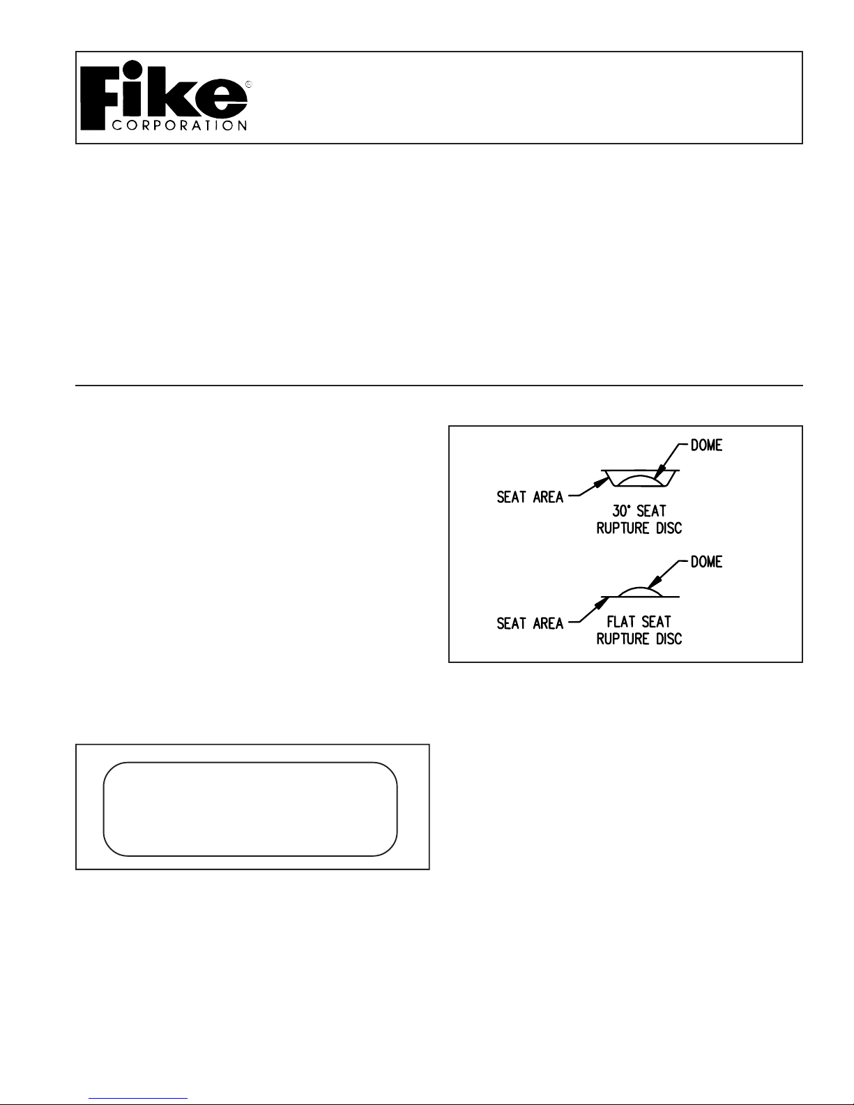
3. Inspect the rupture disc for damage. Look for dents,
scratches or dings in the seat area or dents in the dome of
the rupture disc. (See Figure 2)
B. NEW HOLDER
Handle rupture disc holders with care. Damage to the
rupture disc holder could affect the performance of the
rupture disc.
1. After removing the rupture disc holder from it s packaging,
unscrew the holddown nut and disassemble.
2. Discard the white shipping protector which is between
the base and holddown.
3. Inspect the seat area for scratches, dents, nicks or dirt.
Flaws may adversely affect sealing and disc burst pressure.

C. EXISTING HOLDER
1. For ease of installation, carefully remove the rupture
disc assembly from piping. (See Figures 3 and 4)
2. Separate rupture disc holder components.
3. Remove the rupture disc from its holder .
4. Inspect the seat area of the rupture disc holder. Look for
scratches, nicks, corrosion or deposits left from the media.
5. If necessary , clean the seat area with a solvent that is
compatible with your media. If this does not remove dirt,
hand polish the seat area with ScotchBrite, fine emery cloth
or #0000 steel wool. DO NOT MACHINE THE RUPTURE
DISC HOLDER! If scratches, nicks, corrosion or deposits
from the media cannot be removed by hand, contact the
factory.
WARNING: Inversion of the holddown ring (inst alling
the ring upside down) may result in unexpected
performance characteristics, such as premature
opening or increased burst pressures.
Figure 3: Screw T ype - 30o Seat
D. ASSEMBL Y
WARNING: Before attempting to assemble the rupture
disc and rupture disc holder, confirm that the seat area
of the rupture disc is designed to fit the rupture disc
holder.
1. Place rupture disc in the inlet of the rupture disc holder
with the dome pointing in the direction of flow.
2. Place the holddown ring on the rupture disc. Refer to
Figure 3 for proper orientation of 30
proper orientation of flat seat.
3. Screw the outlet into place, hand tight.
4. Check holder rating and type located on the side of the
holder. Refer to Table 1 for torque values. Locate the table
with the corresponding type and rating. Locate burst pressure. The column to the right contains the required torque in
ft-lbs.
5. T orque holddown nut to required torque.
o
seat and Figure 4 for
Figure 4: Screw T ype - Flat Seat
 Loading...