

Fike 326-0021 Installation And Maintenance Instructions Manual
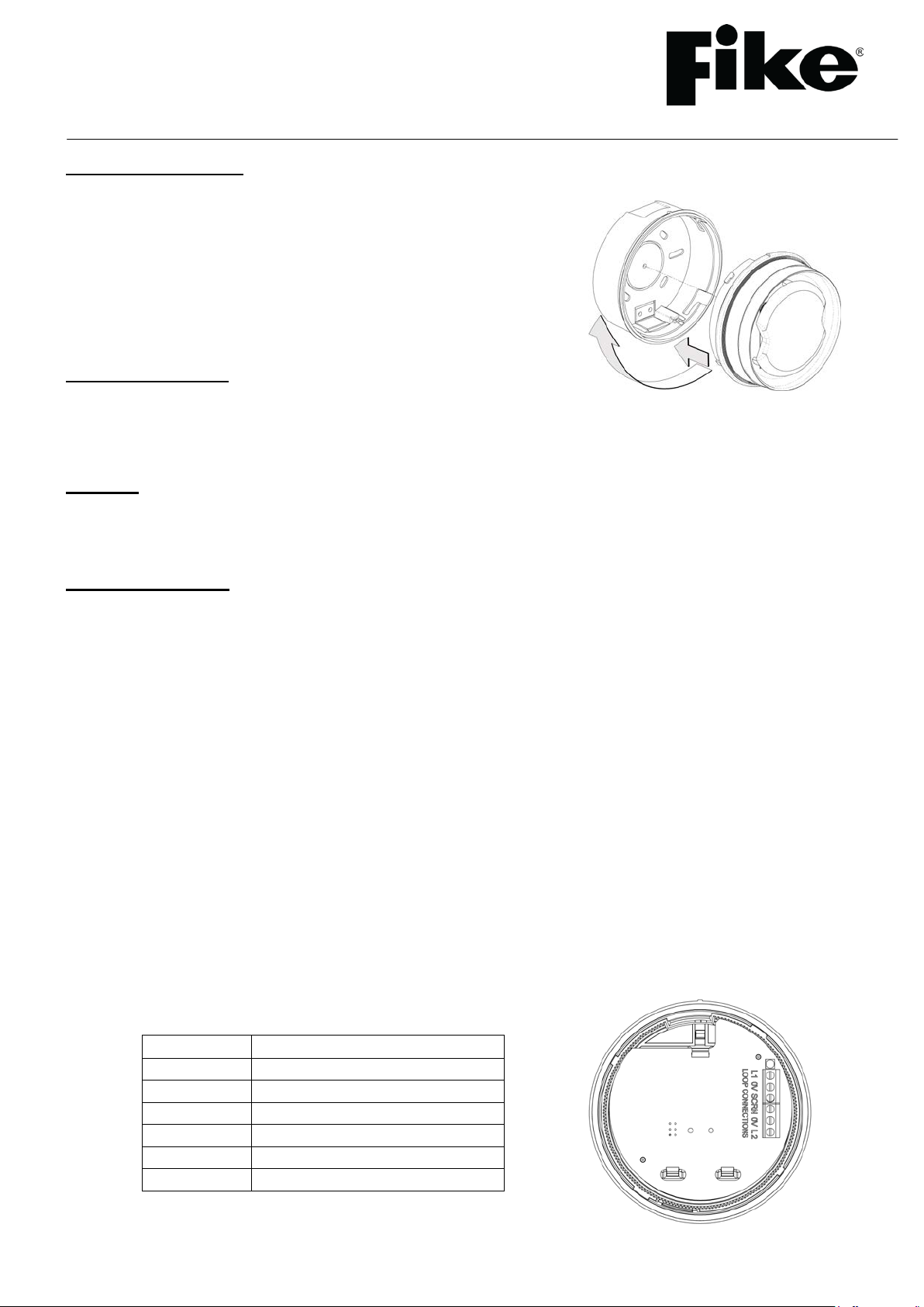
Terminal
Description
L1
Loop +ve IN
0V
Loop -ve IN
SCRN
Screen IN
SCRN
Screen OUT
0V
Loop -ve OUT
L2
Loop +ve OUT
INSTALLATION AND MAINTENANCE INSTRUCTIONS
326-0021 Sita Sounder/Strobe
with Low Profile Base
General Description
The Sita Sounder/Strobe unit allows for audible and visual indication when
the system enters an alarm condition. This is an addressable unit that
attaches to the loop. Digital communication technology to the control panel
is implemented allowing for accurate data transfer at high transmission
speeds. This device is only compatible with the Sita 200+, Duonet and
Quadnet ranges of control panels.
Before Installation
The Sounder/Strobe mus t be ins talled in compliance with the control panel installation manual. The installation must
also meet the requirements of any local authority. For maximum performance the device should be installed in
compliance with BS 5839 Pt1 : 2002 + A2 : 2008.
Spacing
Fike recommends spacing of sounders/strobes in accordance with BS 5839. For more specific information
regarding sounder spacing, placement and special applications please refer to BS 5839 Pt1 : 2002 + A2 : 2008.
Device Installation
The base moulding should be positioned so that access to the locking feature is concealed from general view to
lessen the possibility of unauthorised removal of the device.
Drill or break out the cable entry region(s) in the base moulding as required.
Drill out the desired mounting holes through hole / slot guides as required. Affix the base moulding to a flat surface
using a minimum of 2 screws.
All wiring must be ins talled in compliance with the recommendations laid out by BS 5839 as well as any special
recommendations documented in the control panel ins tallation manual. The cabling used should be of a 2-core
1.5mm
It is to be wired in the form of a screened 2-core loop returning to the control panel. The use of spurs on
this system is not permitted. Cables may be terminated into the connector, as shown below. Care should be
taken when term inating devices to ensure all cables are correctly sleeved and connections are secure. Improper
connections will prevent a system from responding properly in the event of a fire.
2
screened, fire resistant type, with the following characteristics:
Max Capacitance Core to Screen ................................................... 180pF / m
Max Capacitance Core to Core....................................................... 100pF / m
Max Inductance ............................................................................... 1.0mH / km
Max Resistance Two Core Screened 1.5mm² ................................ 12.1Ω / km
26-0980 Issue 6
Type
Description
Sound Pattern:
SP0
Sounder off
SP1
Single tone, 970 Hz continuous
SP2
Pulsed UK alert signal, 970 Hz 1s on, 1s off
SP3
Dual tone UK evacuate signal, 970 Hz 0.25s, 800 Hz 0.25s
SP4
This sound pattern is not supported in this product
SP5
Slow whoop up, 500 to 1200 Hz over 3s, 0.5s off
SP6
Sweep down, 1200 Hz to 500 Hz over 1s
SP7
Dual tone French warble, 550 Hz 0.1s, 440 Hz 400ms
Sound Volume:
L/M/H
Low, medium and high settings are available. See the Control Panel Engineering and Commissioning
Instructions for further details
The Loop +ve (positive) IN and the Loop +ve (positive) OUT connections are split within the module. For cable
continuity readings at the comm issioning stage they must be temporarily removed and connec ted through. Please
remember that all high voltage testing m ust be carried out before the installation of the electronics, otherwise the
electronics will be damaged. Please also note that the SCRN terminal should only be connected to the loop screen
and NOT the building earth.
Once all testing has been carried out on the cabling and continuity & insulation has been proven, the
Sounder/Strobe unit can be assembled.
NOTE: Before installing the Sounder/Strobe remember to note the ser ial number of t he device (located on the rear
of the unit) on to your drawings or configuration sheets to enable you to prove its location later. The address
allocation for the device is carried out automatic ally by the control panel whilst in initialisation mode, so addresses
do not need to be set manually. See the system Installation and Operating Instructions for further details.
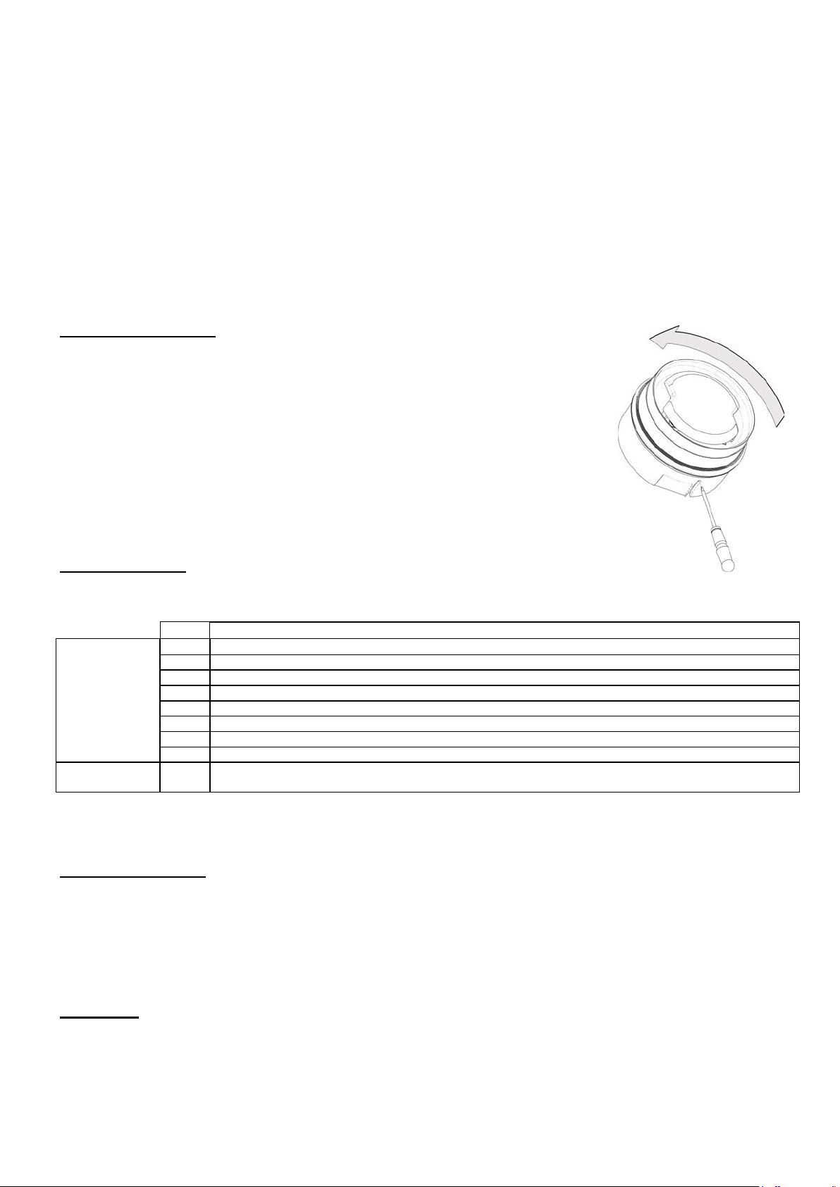
Tamper Resistance
The unit incorporates a locking mechanism which helps prevent unauthorised removal
from the base. To fit, gently insert the device positioned so that the alignment mark on
rim is rotated slightly anti clockwise relative to the alignment mark on the base. Rotate
clockwise until the device drops in and the alignment marks meet. The locking clip will
click.
To remove the device: depress the locking clip by inserting a small diameter tool, such
as a jeweller’s screwdriver, through the hole in the base as shown.
The device should then be turned anti-clockwise allowing it to be removed from the
base.
Device Settings
The sounder modes may be configured using the relevant panel software configuration package.
See the Engineering & Commissioning Manual for your control panel (Sita, Duonet or Quadnet) for further
details of how to program the above.
Beacon Operation
The unit includes a Visual Indication Beacon. This consists of a number of high output LEDs.
The beacon will start to operate when the device receives a comm and to activate its sounder, even if the sound
pattern is set to SP0 - Sounder off. If the beacon only is required to operate, Sound Pattern SP0 must be selected
via the configuration software.
Power Up
The Sita Sounder/Strobe requires approximately one minute on power up to boot up its processor, charge for alarm
operation and settle down to normal operation. Do not sound the alarms within the first minute after initializing the
loop.
26-0980 Issue 6
 Loading...