

Fike 204-0003 Twinflex Multipoint ASD, 204-0001 Twinflex Multipoint ASD, 204-0012 Twinflex Multipoint ASD Installation And Maintenance Instructions Manual
INSTALLATION AND MAINTENANCE INSTRUCTIONS
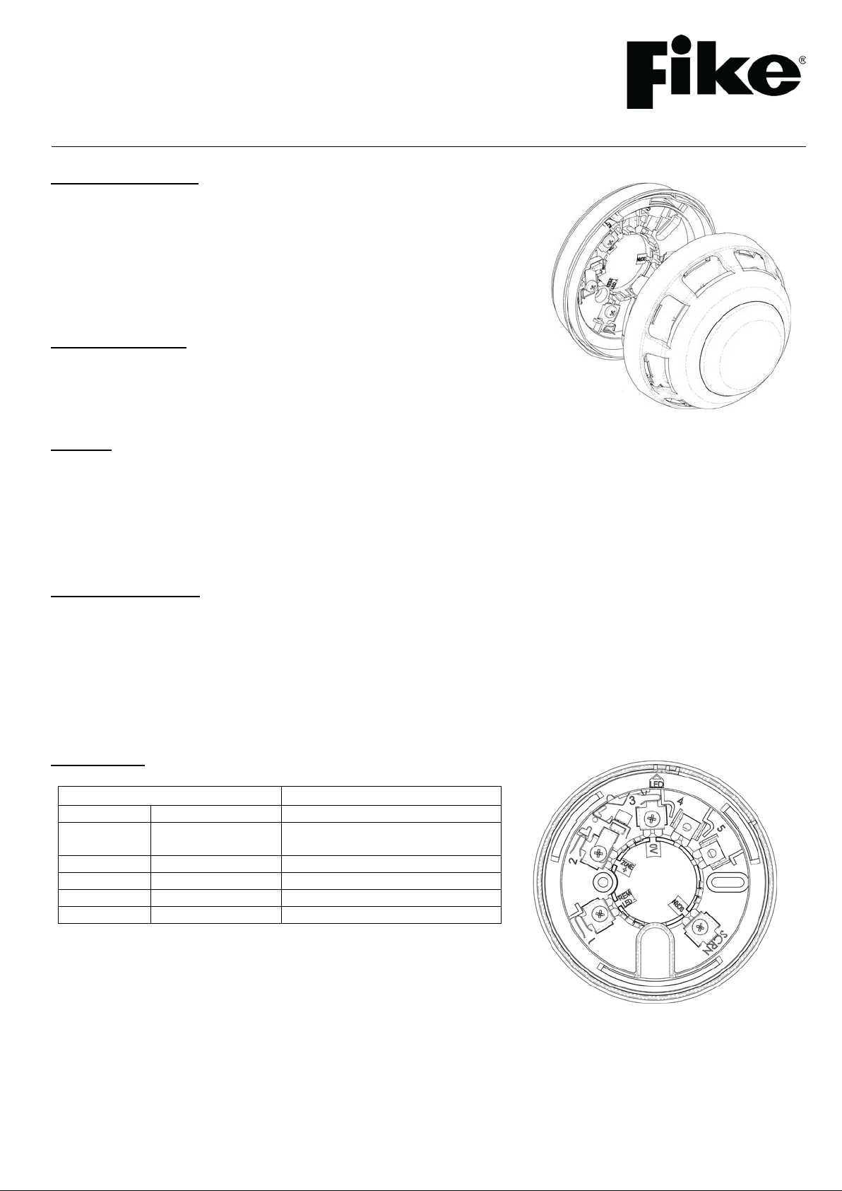
Terminal
Description
1
REM LED –
Remote LED 0V (-VE)
Zone In/Out +VE and Remote
LED +VE
3
0V
Zone In/Out 0V
4
Not Fitted
N/A 5 Not Fitted
N/A
SCRN
SCRN
Screen
204-0003 Twinflex Multipoint ASD Detector,
204-0001 Twinflex Multipoint ASD with Sounder,
204-0012 Twinflex Multipoint ASD with Sounder / Strobe
General Description
The Twinflex Multipoint ASD is a plug-in type smoke detector that utilises a photoelectric sensing chamber to make a measurem ent corre spo n ding t o smoke den sity .
The device also incorporates a thermistor sensing circuit to allow for accurate heat
measurement. These elements allow the device to be configured to a smoke, heat or
combined setting. This device is only compatible with the Twinflex control panels (and
their associated detection and alarm equipment) and may also incorporate a sounder
beacon (ignore all references to sounders/beacons if your device has no
sounder/beacon).
Before Installation
The detector must be installed in compliance with the control panel installation
manual. The installation must also meet the requirements of any local authority. For
maximum performance the detector should be installed in compliance with BS58391:2013.
Spacing
Fike recommends spacing detectors in accordance with BS5839-1:2013. Due to the effects of IR and possible magnetic
interference, detectors should not be fitted any closer than 500mm (preferably 1000mm) to a light fitting or any other source of IR or
EMI. In addition to this recommendation the device should be mounted so that the indication LED is facing towards the light fitting.
For more specific information regarding detector spacing, placement and special applications please refer to BS5839-1:2013.
Note: As with other optical detectors, this device should not be located where subjected to high levels or pulses of light or infra red
light, as this may cause false alarms or faults.
Detector Installation
All wiring must be installed in compliance with the recommendations laid out by BS5839-1:2013 as well as any special
recommendations documented in the control panel installation manual. The cabling used should be of a 2-core 1.5mm2 screened,
fire resistant type (e.g. FP200 equivalent), and is to be wired in the form of a screened 2-core radial circuit (with no spurs) from the
control panel, terminating at the last (“End of Line”) device.
Fix the detector base in a suitable horizontal position using the two screw slots provided, remembering to allow enough cable
length for termination. You may then terminate your cables directly into the terminal block according to the terminal labels. It is
important to maintain the screen continuity in order to protect against data corruption from interference.
Connections
2 ZONE +
26-0947 Issue 10
31/07/18
SWITCH OFF
SWITCH ON
1 2 3 4 5 6 7 8
O N
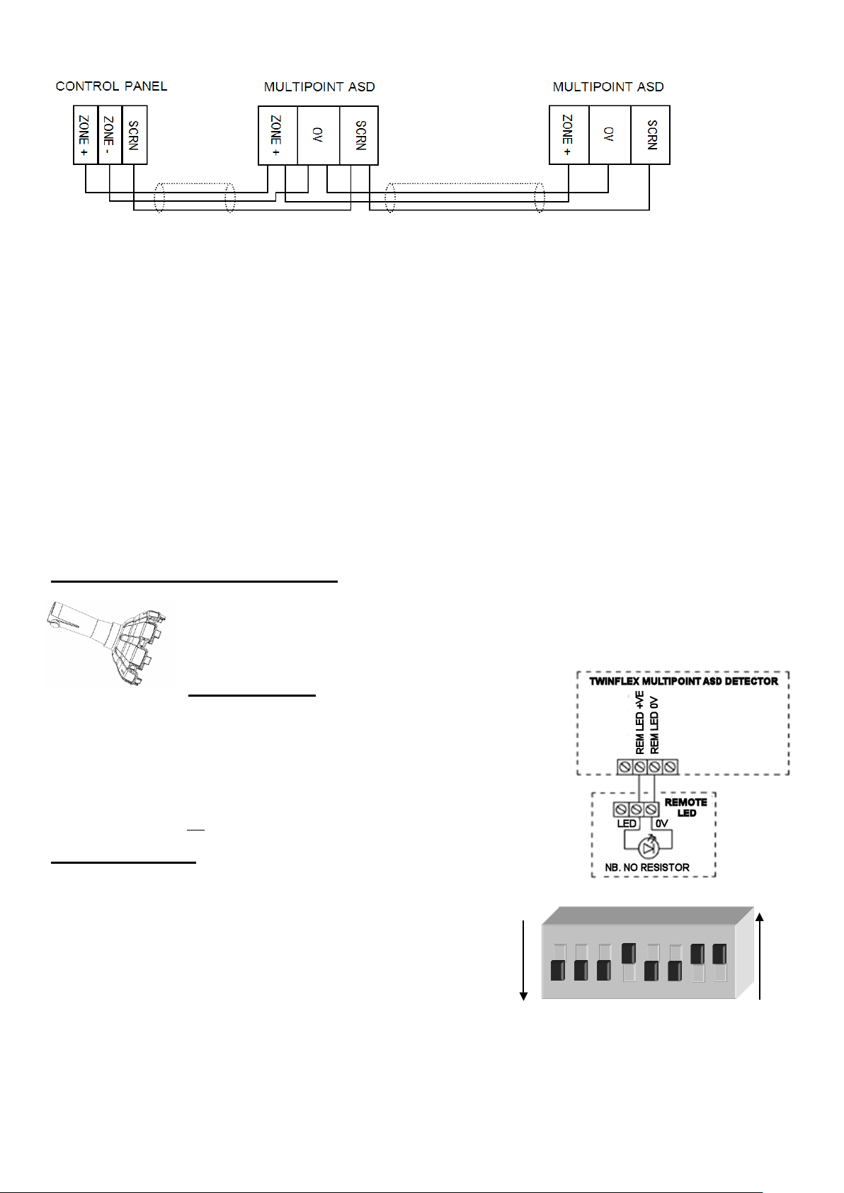
Twinflex Multipoint ASD Detectors can be mixed on the same zone as other types of Twinflex device (e.g. Twinflex Call-points and
earlier detectors). If mixed with earlier detectors, the zone must be set to ‘CP/DET’ and not ‘CP/SM/HT’. The above diagram shows
how to make the zone positive, zone negative and screen connections between the control panel and Twinflex Multipoint ASD
Detectors. Refer to the instruction leaflets supplied with other Twinflex devices for their equivalent wiring/terminal labelling details.
Please note that the SCRN terminal on the detector bases should only be connected to the zone cable screen and NOT to the
building earth. The cable screen is connected to earth at the panel end only, via the zone “SCRN” terminal (or EARTH terminal on
the Twinflex V3 2/4/8 Zone panels). It is important to maintain the screen continuity in order to protect against data corruption from
interference.
Please remember that all high voltage testing must be carried out before the installation of the detector base or electronics, as this
will c ause damage (a small electronics module is also present in base). Once all testing has been carried out on the cabling and
‘continuity & integrity’ has been proven, the detection base & head may be fitted. Before fitting the detector head program the
device settings via the on-board DIL switches, remembering to set the EOL for the last device.
Remember that the device at the end of the line must have its EOL signal activated using the relevant DIL
switch. Do not use a resistor or capacitor (or another manufacturer’s End of Line device) as the end of line,
as this may prevent correct operation o f th e zone.
To install the detection head, locate the pins and gently twist until the unit locks in place.
Tamper Resistance and Head Removal
The ASD detector incorporates a tamper resistant locking mechanism that prevents its removal from the
base without the use of a special tool. To remove the device, the tool should be attached over the detector
and turned anti-clockwise allowing the detector to be removed from the base
Remote Indicator
The remote LED terminals (‘Remote LED + / -’) may be used to connect a separate LED
(Pt No. 600-0092). The LED functions are as follows:
• 5ms every 5 seconds: End of Line
• 5ms every 1.3 seconds: Fault
• 350ms every 0.7 seconds: Fire detected by detector
• Continuous: Fire detected by detector and processed at panel
• 100uS pulse every 20seconds in standby (2 pulses if set to heat)
Note that the LED does not require a resistor.
DIL Switch Settings
The detector DIL switches may be used to program the operation of the Multipoint ASD Detector. They may be altered when the
device is removed from the base. If a heat detection mode is selected then
use the ‘HEAT’ labels supplied to label the base of the detect or clearly .
The last device on the circuit must have the EOL signal enabled (switch
number 1 in the ‘ON’ position).
*If the Multipoint ASD Detector i s used with the SRP panel, DIL swi tch 2 must
be set in the OFF position, (Logical Link OFF). DIL switches 6 must be ON & 7
must be OFF, (for continuous sound pattern).
The SRP panel controls the sound pattern so if the Multipoint ASD Detector is set to anything other than continuous sound it will conflict
with the SRP panel.
26-0947 Issue 10
.
31/07/18
 Loading...