

Fike 20-040, 20-046 User Manual
20-040 and 20-046 COUNTDOWN TIMER
PRODUCT INFORMATION
Description
The Fike 20-040 & 20-046 Countdown Timers are accessory
units for use with Fike Fire Suppression Systems. They are
designed to provide a visual representation of time prior to
release of the agent. They require input from the Fike UL
listed control panel at the start of the pre-discharge state to
initiate their countdown sequence. This countdown can
either be a polarity reversal signal or relay activation,
depending upon the wiring option selected. The countdown
sequence does not reflect abort conditions at the panel. The
timers are sold with manual release switches and/or abort
switches. They are provided with back box of appropriate
size.
SPECIFICATIONS
Input Voltage 24 VDC
Current Consumption 0 mA In Stand-by
Circuit Limitations Class A or B
Dimensions See drawing
Weight 20-040 0.752 lbs 280.6 grams
Operating
Temperature
Operating Humidity 10% to 85% RH, non –
Installation Method Assembly mounts to back-box
Listings and
Approvals
160 mA In Pre-discharge
20-046 1.128 lbs. 421.6 grams
32°F to 120°F
0°C to 49°C
condensing
supplied with the individual unit.
U.L listed S3217
F.M. Approved OY4A4.AY
C.S.F.M. 6760-0900:103
M.E.A. 163-95-E
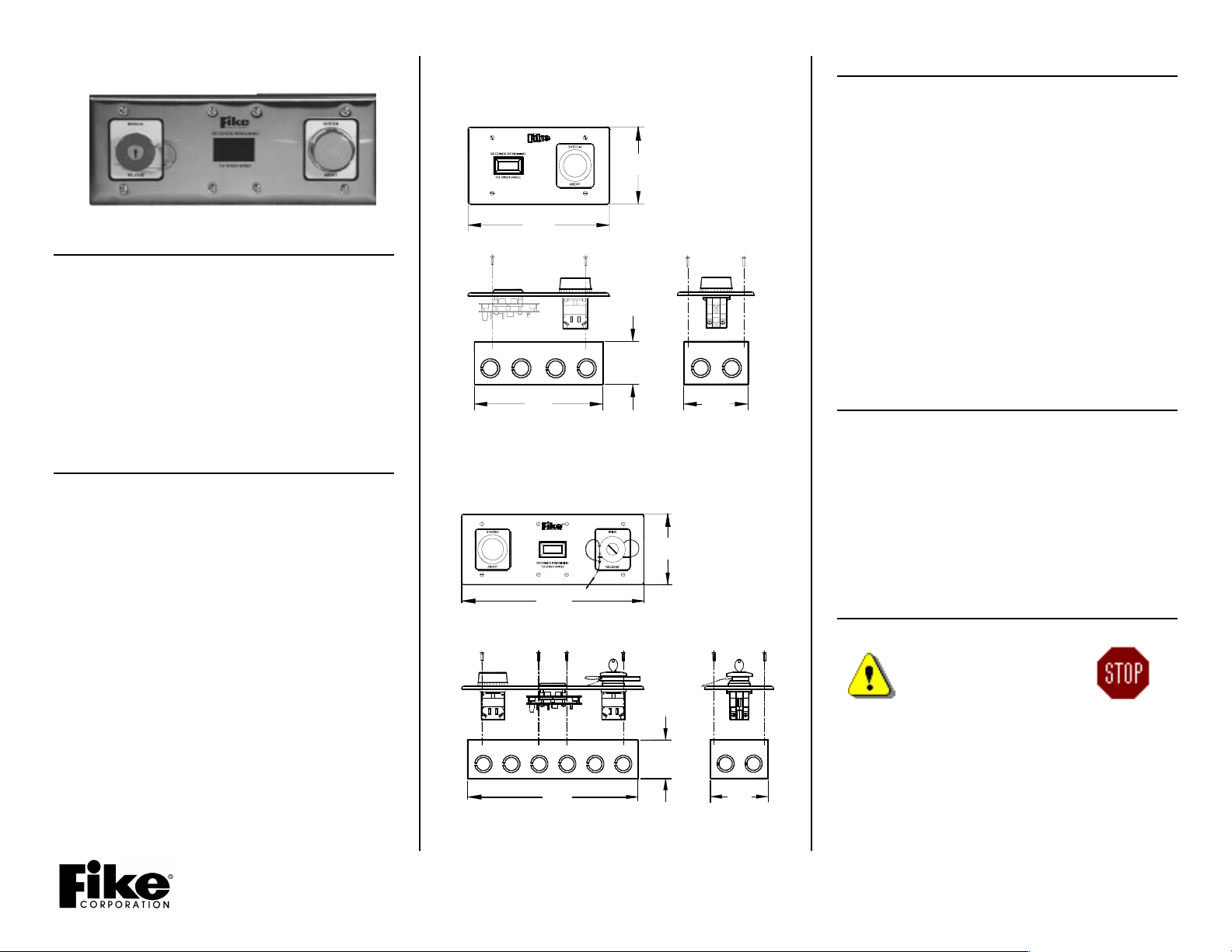
20-040 COUNTDOWN TIMER
WITH ABORT SWITCH
4 1/2"
( 11.43cm )
8 3/16"
( 20.80cm )
2 1/2"
( 6.35cm )
7 3/8"
( 18.73cm )
3 3/4"
( 9.53cm )
20-046 COUNTDOWN TIMER
WITH ABORT SWITCH & MANUAL RELEASE
4 1/2"
( 11.43cm )
11 13/16"
( 28.42cm )
2 1/2"
( 6.35cm )
11.0"
3 3/4"
INSTALLATION & CHECKOUT
1) Disable the Control Panel Agent Release Circuit.
2) Remove all power from the control panel.
3) Connect the field wiring to the countdown timer
terminals according to the wiring diagram provided.(see
reverse side)
4) Adjust the Countdown Timer ten’s and units settings for
the proper time that corresponds to the panel predischarge countdown time.
5) Terminate field wiring on the abort and/or manual
release switch(s).
6) Apply power to the control panel. With the system
disarmed, test the system and verify the proper
operation of the timer. Make adjustment to timer units
settings to reflect accurate timing as per the control
panel. Test the operation of the abort and/or manual
release switch(s).
7) Install the switch plate to the back-box.
OPERATIONS
When the control panel enters the pre-discharge state it
initiates the signal to start the Countdown Timer. The timer
displays the countdown time as determined by the rotary
switch settings. After the time has elapsed, the L.E.D.
display will indicate ‘0’ until power is removed (silenced or
reset) thus resetting the timer.
The operation and installation of the Abort and/or Manual
Release Switch(s) is described in Installation Guide 06-230.
SAFETY NOTICES
Read all of the following warnings and
cautions before attempting to
install or use this device.
Personal injury or accidental
release of the suppression
system may result if these
warnings and cautions are not followed.
CAUTION The Countdown Timer contains static sensitive
components. Handle the timer by the edges only and avoid
touching the integrated components. Keep the timer in the
protective static bag it was shipped in until time of
installation. To prevent damage from static discharge,
always ground yourself with a proper wrist strap before
handling the Countdown Timer.
Installation Guide #06-128
Rev. No.1 10/2001
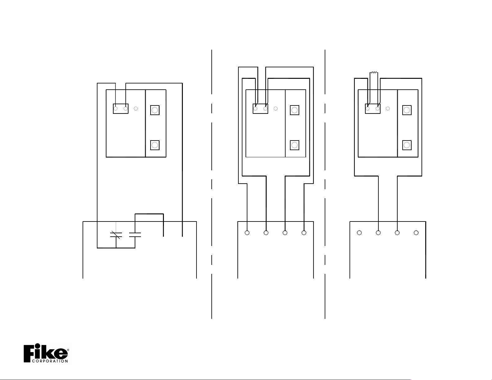
PANEL
EOL.
WIRING DIAGRAMS
-
+
TEN'S
GND
24V
MODULE
TIMER
C
NC
NO
(N/A)
TRIGGER
UNITS
24V
Audible Circuit Class A
Output Relay
+
TIMER
+
+
-
24V
GND
MODULE
+
-
+
TEN'S
GND
TIMER
+
+
24V
MODULE
(N/A)
TRIGGER
UNITS
-
-
-
(N/A)
TRIGGER
+
TEN'S
UNITS
-
-
-
Audible Circuit Class B
PRE-DISCHARGE
Installation Guide #06-128
Rev. No.1 10/2001
AUX
POWER GND
CIRCUIT
RELAY
PANEL
CONTROL
OUTPUT CIRCUIT
"REMOTE TIMER"
PROGRAMMED AS
CONTROL
PANEL
OUTPUT CIRCUIT
"REMOTE TIMER"
PROGRAMMED AS
CONTROL
PANEL
 Loading...