

Fike 10-2256 Product Manual

DIGITAL ALARM COMMUNICATOR
,
OBSOLETE
PRODUCT MANUAL
10-2256
Manual P/N: 06-160
Rev: 1
04/01

FIKE CORPORATION
OBSOLETE
Fike Corporation – Offices
Fike Corporation
World Headquarters
704 South 10
P.O. Box 610
Blue Springs, Missouri 6401 3
U.S.A.
Ph: (816) 229-3405
Fax: (816) 229-5082
th
Street
Fike Europe
Toekomstlaan 52
B-2200 Herentals
Belguim
Ph: 011-32-14-210031
Fax: 011-32-14-210743
Copyright Information
Fike South East Asia
81, Loyang Way
Singapore, 1750
Singapore
Ph: 011-65-545-1188
Fax: 011-65-545-2139
Fike Latina
Avenida Paulista 2202, 3°, cj34
Cerqueira Cesar, Sao Paulo
Brazil, CEP 01310-300
Ph: 011-55-11-251-5244
Fax: 011-55-11-284-8479
Fike Canada
4140 Morris Drive
Burlington, Ontario L7L 5L6
Canada
Ph: (905) 681-3100
Fax: (905) 681-3107
Fike United Kingdom
10-11 Enterprise Estate
Moorfield Road
P.O. Box 540
Guildford, Surrey GU1 1RB
United Kingdom
Ph: 011-44-8700-777-540
Fax: 011-44-7000-777-540
This document may not be reproduced, in who le or in part, b y an y means without the prior ex pres s
written permission of Fike Corporation.
Fike
is a registered trademark of Fike Corporation.
Disclaimers
The information contained in this manual is as accurate as currently possible. This manual is
intended to be an aid to Fike authorized distributors, who have been trained in an approved manner
by Fike, and the user who is a customer of the Fike authorized distributor. Fike does not warrant that
this manual is technically correct, complete, or free from writing problems or that the Fike products
referenced therein are free from minor flaws.
In accordance with our policy of continuing product and system improvement, Fike reserves the right
to change designs or specifications without obligation and without further notice.
Reader Responses
Fike encourages input from our distributors and end users on how we can improve this manual and
the products themselves. Please direct all calls of this nature to Fike’s Product Support Department
at (816) 229-3405.
Any communication received becomes the property of Fike Corporation.
Warranties
Fike provides a one-year limited manufacturer's warranty on this product. The standard
warranty is printed in each Marketing Price List. All warranty returns must be returned from
an authorized Fike Distributor. Contact Fike's Marketing Department for further warranty
information. Fike maintains a repair department that is available to repair and return existing
electronic components or exchange/purchase previously repaired inventory component
(advance replacement). All returns must be approved prior to return. A Return Material
Authorization (RMA) number should be indicated on the box of the item being returned.
Contact the appropriate Regional Sales Manager for further
Digital Alarm Communicator
Manual P/N: 06-160

Content
OBSOLETE
Section 1
Introduction .............................................................................................................................................. 1-1
1.1 Features ....................................................................................................................................................1-1
1.2 Optional Devices ...................................................................................................................................... 1-2
1.3 UL Fire Listed Receivers Compatible with the 10-2256 .........................................................................1-3
1.4 How to Use this Manual ........................................................................................................................... 1-3
Section 2
Agency Requirements ...............................................................................................................2-1
2.1 Telephone Requirements .......................................................................................................................... 2-1
2.2 FCC Warning ...........................................................................................................................................2-2
2.3 UL Listings and Requirements ................................................................................................................ 2-2
10-2256 Requirements: .................................................................................................................2-2
Section 3
Panel Description and Installation ............................................................................3-1
3.1 Panel Description .....................................................................................................................................3-1
3.1.1 Phone Line Monitors ........................................................................................................................ 3-1
3.1.2 Watchdog Circuit .............................................................................................................................. 3-1
3.1.3 Power Loss Reporting ....................................................................................................................... 3-1
3.1.4 EEPROM ..........................................................................................................................................3-2
151086 i
3.1.5 DC Power .......................................................................................................................................... 3-2
3.1.6 Indicator Lights ................................................................................................................................. 3-2
3.2 Wiring ......................................................................................................................................................3-3
3.2.1 Wiring Precautions ........................................................................................................................... 3-3
3.2.2 Connector Descriptions ..................................................................................................................... 3-3
3.2.3 Wiring and Board Layout Diagram ..................................................................................................3-4
3.2.4 Electrical Ratings .............................................................................................................................. 3-4
3.2.5 Wire Routing ..................................................................................................................................... 3-5
3.3 Mounting and Grounding ......................................................................................................................... 3-6
3.3.1 Grounding the 10-2256 Board ..........................................................................................................3-6
3.3.2 Grounding the 10-2256 Cover ..........................................................................................................3-7
3.4 Channel Operation and Wiring ................................................................................................................3-8

Model 10-2256 Fire Slave Communicator Installation Manual
OBSOLETE
3.4.1 Dry Contact ....................................................................................................................................... 3-8
3.5 AC Monitoring .........................................................................................................................................3-9
For SHP/Rhino: .............................................................................................................................3-9
For Cheetah: .................................................................................................................................. 3-9
3.5.1 Monitor AC (SHP or Rhino) ..........................................................................................................3-10
3.6 Relay Connection ...................................................................................................................................3-11
3.7 Telephone Line Connection ...................................................................................................................3-12
3.8 Remote Annunciator Installation ...........................................................................................................3-13
3.8.1 10-2257 Connection ........................................................................................................................3-13
Section 4
Normal Operation .............................................................................................................................4-1
4.1 10-2257 Operation ....................................................................................................................................4-1
4.1.1 Power LED Indicator ........................................................................................................................4-1
4.1.2 Buzzer ...............................................................................................................................................4-1
4.1.3 10-2257 Key Functions .....................................................................................................................4-2
4.2 Operating Modes ...................................................................................................................................... 4-3
Section 5
Programming ..........................................................................................................................................5-1
5.1 Programming with the 10-2257 Remote Annunciator .............................................................................5-2
5.2 Programming with the 06-151 Downloading Software ........................................................................... 5-3
5.3 Programming Options ..............................................................................................................................5-3
Section 6
Reporting .....................................................................................................................................................6-1
6.1 SIA Format ...............................................................................................................................................6-2
6.2 Silent Knight FSK and 4+2 Formats ........................................................................................................6-3
6.3 Radionics BFSK .......................................................................................................................................6-4
6.4 Silent Knight 3/1 and Sescoa 3/1 ............................................................................................................. 6-5
Section 7
Troubleshooting .................................................................................................................................7-1
7.1 Accu-Zone( Troubleshooting (Mode 25) .................................................................................................7-1
7.2 System Messages ......................................................................................................................................7-3
ii 151086

Section 1
OBSOLETE
Introduction
The Fike Model 10-2256 is a low-cost slave communicator that meets the requirements for UL
864, NFPA 72 Fire Alarm Systems for Central Station Service and NFPA 72 Remote Supervising
Station Fire Alarm Systems.
1.1 Features
• Compatibility with the Security Industry Association (SIA) reporting format and several other
standard reporting formats.
• Four channel (zone) inputs for system status reporting: fire alarm (channel or zone 1); system
trouble—channel 2 (or zone 2); supervisory—channel 3 (or zone 3); and miscellaneous—
channel 4 (or zone 4).
• Optional two-number dialing with same or different account codes and reporting formats.
Alarms, troubles, disables, and tests can be programmed to be reported to either or both
numbers.
• Programmable as rotary-only or as Touch-Tone/rotary dialing.
• Built-in dual phone line-seizure circuit.
• Dual phone line monitor circuits.
• Transient voltage protection of phone lines.
• Built-in audible trouble buzzer with a loudness of 80 decibels (dB) at 30 cm (that is, 300 mm
151086 1-1
or, approximately, 12 inches).
• One relay output, programmable for alarm or trouble conditions.
• Light-emitting diodes (LEDs), visible from front of enclosure, indicating: trouble condition
(yellow); presence of DC power (green), phone line 1 trouble (red); and phone line 2 trouble
(red).
• Easy, English-language programming using Model 10-2257 Remote Annunciator.
• Fuseless design, 24 VDC.
• Electrically erasable read-only memory (EEPROM) for nonvolatile storage of all
programmable option data. Eliminates the need to reprogram the communicator if power is
lost.

Model 10-2256 Fire Slave Communicator Installation Manual
OBSOLETE
• Built-in watchdog circuit that monitors the operation of the 10-2256 and resets the
communicator if a fault is detected.
• Operates by contact closure input from the control panel.
• Model 10-2256 can directly monitor control panel's primary power.
• Compatibility with many Underwriters Laboratories (UL) Fire Listed receivers. (See Section
1.3 for list.)
• Model 10-2256 housed in a 10" x 10" metal enclosure.
1.2 Optional Devices
The following accessories are available for use with the 10-2256:
• Model 10-2257 Remote Annunciator for programming, troubleshooting, and system
operation. Only one model 10-2257 can be used. The 10-2257 can be permanently connected
(but is not supervised).
• Cable for 10-2257, P/N 10-2258.
• 06-151 Downloading Software for remote programming.
• 10-2259 Modem. Required if the 06-151 downloading software is used.
1-2 151086
Introduction
OBSOLETE
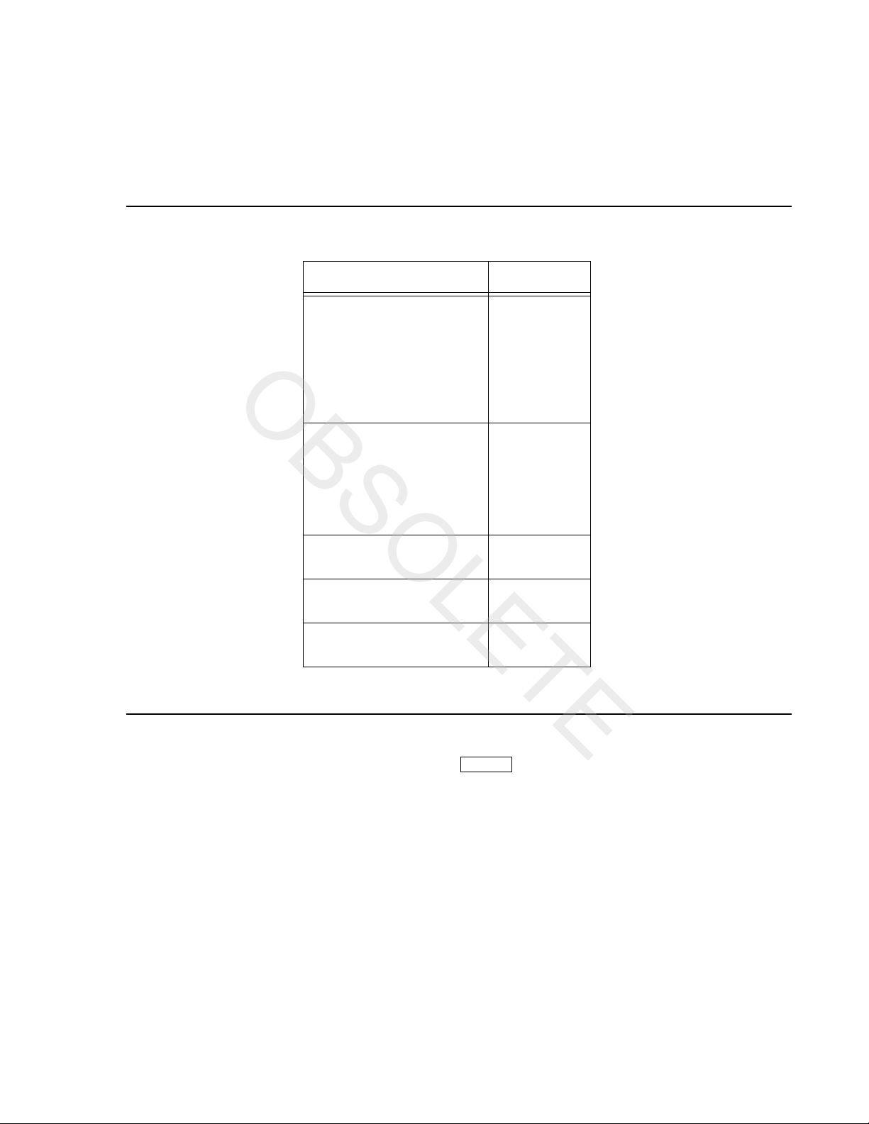
1.3 UL Fire Listed Receivers Compatible with the 10-2256
The following UL Listed receivers are compatible with the 10-2256:
Receiver Formats
Silent Knight Model 9000 BFSK14
BFSK23
FSK
SK 3/1
SK 4+2
SIA8
SIA20
Osborn & Hoffman QuickAlert BFSK14
BFSK23
SK 3/1
SK 4+2
SIA8
SIA20
Ademco 685 SK 3/1
SK 4+2
FBI CP220 SK 3/1
SK 4+2
Radionics D6500 BFSK14
BFSK23
1.4 How to Use this Manual
In this manual, a rectangle represents a key that you press if you are using the optional Model 102257 Remote Annunciator. For example, “Press " means “Press the <ENTER> key.”
ENTER
151086 1-3

Model 10-2256 Fire Slave Communicator Installation Manual
OBSOLETE
1-4 151086

Section 2
OBSOLETE
Agency Requirements
2.1 Telephone Requirements
1. If requested by the telephone company, the following information must be provided before
connecting this device to the phone lines:
A. Manufacturer: Silent Knight Security Systems
B. Model Number: 10-2256
C. FCC Registration Number: AC6USA-75160-AL-E
Ringer equivalence: 0.1B
D. Type of jack (to be installed by the telephone company): RJ31X
2. This device may not be directly connected to coin telephone or party line services.
3. This device cannot be adjusted or repaired in the field. In case of trouble with the device,
notify the installing company or return to:
Fike Protection Systems
704 So. 10th St.
Blue Spring, MO 64013
816-229-3405
4. If the Model 10-2256 causes harm to the telephone network, the telephone company will
151086 2-1
notify the user in advance that temporary discontinuance of service may be required. If
advance notice is not practical, the telephone company will notify the user as soon as possible.
The user has the right to file a complaint with the Federal Communications Commission if he
or she believes it is necessary.
5. The telephone company may make changes in its facilities, equipment, operations, or proce-
dures that could affect the operation of the equipment. If this happens, the telephone company
will provide advance notice so that you can make the necessary modifications to maintain
uninterrupted service.

Model 10-2256 Fire Slave Communicator Installation Manual
OBSOLETE
2.2 FCC Warning
WARNING:
This equipment generates and uses radio frequency energy. If not installed and used in strict
accordance with this manual, it may cause harmful interference to radio communications. It has
been tested and found to comply with the limits for a Class A computing device pursuant to
Subpart J of Part 15 of FCC Rules, which are designed to provide reasonable protection against
such interference when operated in a commercial environment. Operation of this equipment in a
residential area is likely to cause interference. If this occurs, the user will be required, at his or
her own expense, to take whatever measures may be required to correct the interference.
2.3 UL Listings and Requirements
Model Listed As:
Signaling device for use in Fire Alarm Systems for
10-2256
* From National Fire Alarm Code, 1993 Edition. Published by National Fire Protection
Association, 1 Batterymarch Park, Quincy, MA 02269-9904.
All UL installations must comply with the requirements described below. Refer to the control
unit's installation manual for complete information.
10-2256 Requirements:
1. The 10-2256 and the UL listed compatible fire control must be installed in the same room. All
wiring between the 10-2256 and the UL Listed compatible fire control panel must be enclosed
in conduit.
2. All electrical connections must comply with the ratings shown in section 3.2.4.
3. In a remote signaling installation, the control unit, slave dialer, and receiver at the remote site
must all be UL listed for remote signaling.
Central Station Service.
Signaling device for use in Remote Supervising Fire
Alarm Systems.
*NFPA 72 Chapter
(for more information):
4-3
4-5
2-2 151086

Section 3
OBSOLETE
Panel Description and Installation
CAUTION:
To avoid the risk of electrical shock, make sure the main control power is OFF when wiring. DO
NOT apply power until wiring is completed following the procedures described in this manual.
3.1 Panel Description
3.1.1 Phone Line Monitors
The 10-2256 dialer has two phone line monitor circuits, which detect phone line faults by
monitoring their voltages. These circuits feature a 40 to 90 second delay before a line fault is
reported as a trouble. When a fault is detected for longer than this amount of time, the audible
trouble signal will sound, the message will be displayed on the 10-2257 annunciator liquid crystal
display (LCD) (if used), and the trouble will be reported to the central station.
Note: To comply with industry standards, this product is equipped with line seizure. This means that any time the sys-
tem's dialer needs to communicate with the central station, it will NOT be possible to use any telephones that
are on the same line(s) as the fire system. Normally this condition will last less than one minute, but could last
for as long as 15 minutes under adverse telephone circuit conditions.
3.1.2 Watchdog Circuit
If the 10-2256 stops running, the watchdog circuit automatically detects the problem and attempts
to resume normal operation by resetting the communicator. Each time the watchdog circuit resets
the system, it also sounds the trouble signal.
3.1.3 Power Loss Reporting
The 10-2256 will report low AC conditions. For Cheetah the 10-2256 monitors the trouble relay.
For SHP/Rhino the 10-2256 monitors the control panel's main AC power input.
The AC report delay time is programmable. See Section 5, Step 20.
151086 3-1

Model 10-2256 Fire Slave Communicator Installation Manual
OBSOLETE
3.1.4 EEPROM
The electrically erasable read-only memory (EEPROM) is used to store specific information such
as system configuration, telephone numbers, reporting format, and account numbers. The
EEPROM retains the programmed information even when all electrical power is removed. It can
be programmed more than 1,000 times without losing its ability to store information.
3.1.5 DC Power
The 10-2256 operates on 18-40 VDC rectified power from the main fire control panel.
3.1.6 Indicator Lights
The 10-2256 has four LEDs to indicate status.
TROUBLE LED (yellow)
ON - A system trouble condition exists.
OFF - No trouble condition exists.
DC POWER LED (green)
ON - The panel is running on DC power.
OFF - The panel has lost all power.
PHONE LINE 1 LED (red)
ON - Phone line 1 has a trouble condition.
OFF - Normal condition.
PHONE LINE 2 LED (red)
ON - Phone line 2 has a trouble condition.
OFF - Normal condition.
3-2 151086

Panel Description and Installation
OBSOLETE
3.2 Wiring
3.2.1 Wiring Precautions
High and low voltage must be separated by at least one-quarter inch. See Section 3.2.5 for more
information.
High current input/output: AC monitoring (if monitored directly)
Low current input/output: 24 VDC power and channel (zone) wiring
Audio input/output: Telephone wiring
High frequency noise, such as that produced by the inductive reactance of a bell, can also be
reduced by running the wire through ferrite shield beads or by wrapping it around a ferrite toroid.
3.2.2 Connector Descriptions
PIN Connector Function
P1 DC power
P2 Channel (zone) inputs
P4 10-2257 connect
P5 Low AC channel input
151086 3-3

Model 10-2256 Fire Slave Communicator Installation Manual
OBSOLETE
3.2.3 Wiring and Board Layout Diagram
Figure 3-1 Model 10-2256 Wiring and Board Layout
3.2.4 Electrical Ratings
PRIMARY DC: VDC: 18 - 40
Current draw, standby at 24 VDC
143 mA max. with annunciator attached 84 mA max. without annunciator
Current draw, alarm at 24 VDC
227 mA max. with annunciator attached 154 mA max. without annunciator
AC RATING: 45 mA max.
CHANNEL (ZONE) INPUTS: 0 - 30 VDC input 10 mA max. current draw
MAX. WATCHDOG RESPONSE: 50 seconds
3-4 151086
Panel Description and Installation
OBSOLETE
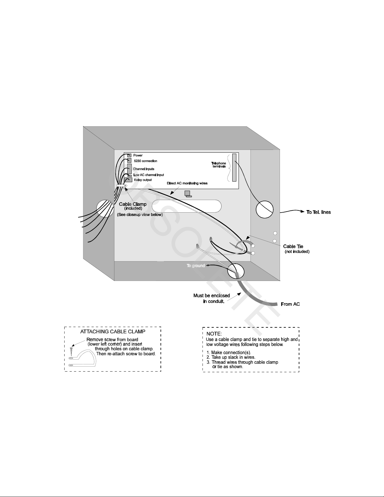
3.2.5 Wire Routing
High voltage and low voltage inputs must be separated by at least one-quarter inch and must be
wired through different knockout holes in the fire control cabinet to maintain the separation.
Figure 3-2 below shows an example of how to route the wire.
Figure 3-2 Routing Wire for the 10-2256
151086 3-5
 Loading...