

Page 1
Installation Manual
10-071, Cheetah Xi 50
Addressable Fire Suppression Control System
P/N 06-369, Rev. 6
September 2015
Page 2

transmit, transcribe, or any part of this manual without express, written
This manual contains proprietary information intended for distribution to
Installation in accordance with this manual, applicable codes, and the
DEVELOPED BY
COPYRIGHT NOTICE
TRADEMARKS
QUALITY
Fike
704 SW 10
th
Street
P.O. Box 610
Blue Springs, Missouri 64013 U.S.A.
Phone: (800) 979-FIKE (3453)
(816) 229-3405
Fax: (816) 229-0314
Copyright 2015. All rights reserved.
Fike copyrights this m anual and produc ts it describes. You may not reproduc e,
permission from Fike.
authorized persons or companies for the sole purpose of conducting business
with Fike. If you distribute any information contained in this manual to
unauthorized persons, you have violated all distributor agreements and we may
take legal action.
Fike is a registered trademark of Fike.
Cheetah
®
is a registered trademark of Fike.
Fike has maintained ISO 9001 certification since 1996. Prior to shipment, we
thoroughly test our pr oduc ts and r ev iew our d ocum entatio n to as sure t he hig hest
quality in all respects.
WARRANTY
Fike provides a one-year limited manufacturer’s warranty on this product. All
warranty returns m ust be returned from an authorized Fike Distributor . Contact
Fike’s Marketing department for further warranty information.
Fike maintains a repair department that is ava ilable to repair and retur n existing
electronic components or exchange/purchase previously repaired inventory
component (advance repla cem ent). All returns m ust be appr ove d prior to retur n.
A Material Return Author ization (MRA) number must be indicated on the box of
the item being returned. Contact the appropriate Regional Sales Manager for
further information regarding product return procedures.
LIMITATIONS OF LIABILITY
instructions of the Authority Having Jurisdiction is mandatory. Fike cannot be
held liable for any incident al or consequential damages arising f rom the loss of
property or other damages or losses resulting from the use or misuse of Fike
products beyond the cost of repair or replac ement of a ny defective com ponents.
Fike reserves the right to make product improvements and change product
specifications at any time.
While every precaution ha s been taken during the preparatio n of this manual to
ensure the accurac y of its content, Fike assumes no respons ibility for errors or
omissions.
Page 3
CONTENT
devices, added FAAST detector.
Added FAAST XT
aspirating smoke detector
Added solenoid protection assembly to
battery calculation
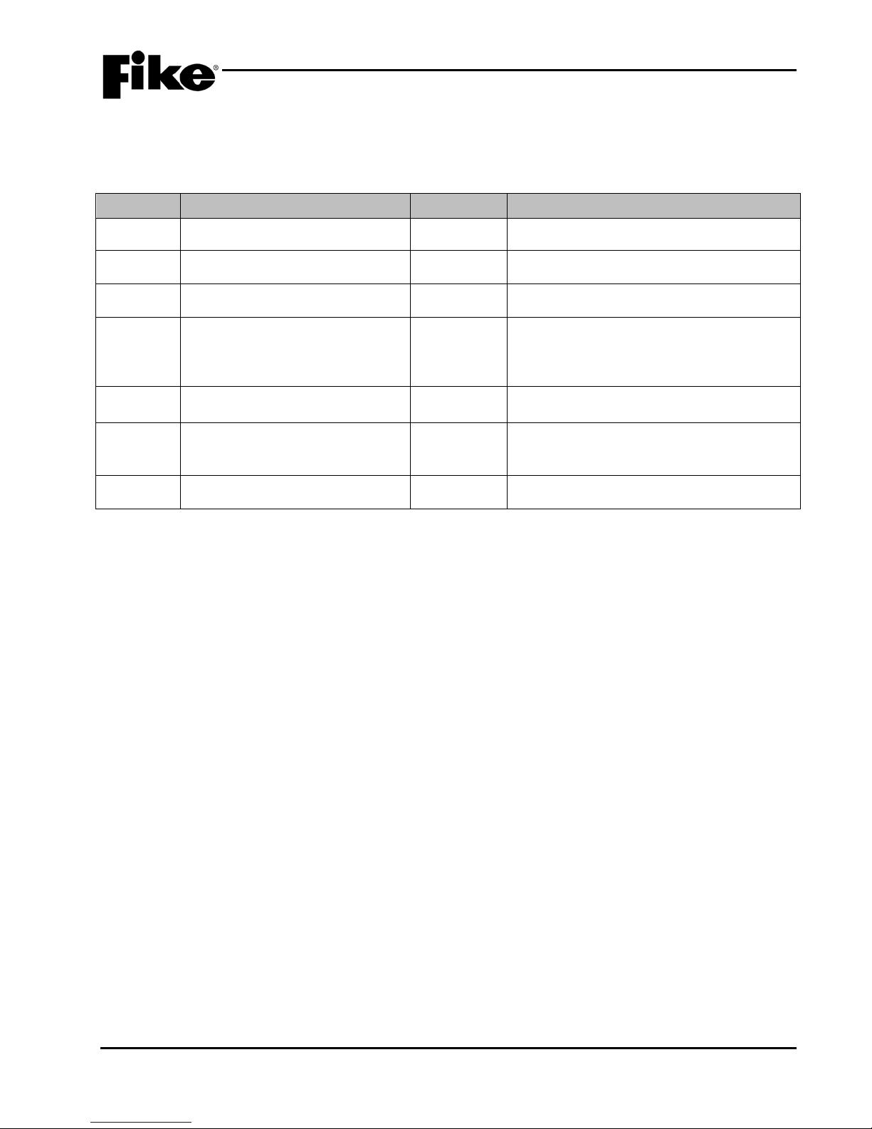
REVISION HISTORY
Document Title: Cheetah Xi 50 Addressable Fire Suppression Control System Installation Manual
Document Reorder Number: 06-369
Revision Section Date Reason for Change
0 All Sections 03/2007 Initial Release
1 Sections 1,2,3,4,7 & Appen dix 08/2008 Added Remote 20 Zone Annunciator
2 Sections 1,2,3 & 6 03/2010 Added IRM Compatibility
Separated manual into individual
3 All Sections 04/2012
4 All Sections 08/2014
Installation and Operation & Programming
manuals, updated list of compatible
5 Section 3.9.6 and Appendix A 02/2015
RCM and updated HLI current draw in
6 All Sections 09/2015 Clarifications and General Updates
UL S2203 Cheetah Xi 50 Installation Manual i
FM P/N: 06-369 Rev 6, 09/2015
Page 4

CONTENT
TABLE OF CONTENTS
SECTION DESCRIPTION PAGE
1.0 Introduction .................................................................................................................... 1-1
1.1 About This Manual ........................................................................................................... 1-1
1.2 Product Support ............................................................................................................... 1-1
1.3 Safety Information ............................................................................................................ 1-1
1.4 Terms Used In This Manual ............................................................................................. 1-2
1.5 Related Docum entat ion ................................................................................................... 1-3
2.0 System Overview ........................................................................................................... 2-1
2.1 System Description .......................................................................................................... 2-1
2.1.1 Cheetah Xi 50 Features ................................................................................................... 2-2
2.1.2 Listings and Approvals ..................................................................................................... 2-3
2.1.3 Agency Standards and Compliance................................................................................. 2-3
2.1.4 Minimum System Configurations ..................................................................................... 2-4
3.0 System Components ..................................................................................................... 3-1
3.1 Basic Equipment Packages ............................................................................................. 3-1
3.2 Cheetah Xi 50 Controller .................................................................................................. 3-1
3.2.1 NAC Circuit Limitations .................................................................................................... 3-5
3.2.2 Controller Test Points/Voltages ....................................................................................... 3-5
3.3 System Enclosure ............................................................................................................ 3-6
3.4 Digital Alarm Communicator Transmitter (DACT) ............................................................ 3-8
3.4.1 DACT Keypad Programmer ............................................................................................. 3-8
3.5 Peripheral Bus Devices .................................................................................................... 3-9
3.5.1 Fourteen Button Remote Display Unit ............................................................................. 3-9
3.5.2 Ten Button Remote Display Unit ...................................................................................... 3-9
3.5.3 Two Button Remote Display Unit ................................................................................... 3-10
3.5.4 Ethernet Module ............................................................................................................. 3-10
3.5.5 Multi-Interface Module (MIM) ......................................................................................... 3-10
3.5.6 Intelligent Graphic Annunciator ...................................................................................... 3-11
3.5.7 Twenty Zone Remote Annunciator ................................................................................ 3-11
3.5.8 Relay Control Assembly ................................................................................................. 3-11
3.5.9 Relay Card ..................................................................................................................... 3-12
3.5.10 Class A Peripheral Bus Card ......................................................................................... 3-12
3.6 Intelligent Detectors ....................................................................................................... 3-13
3.6.1 Photoelectric Smok e Detector ....................................................................................... 3-13
3.6.2 Ionization Smoke Detector ............................................................................................. 3-13
3.6.3 Photo/Heat Combination Detector ................................................................................. 3-14
3.6.4 Heat Detector ................................................................................................................. 3-14
3.6.5 Photoelectric Duct Detector ........................................................................................... 3-15
3.6.5.1 Duct Detector Housing ................................................................................................... 3-15
3.6.6 FAAST Aspirating Smoke Detector ................................................................................ 3-16
3.7 Detector Bases ............................................................................................................... 3-17
3.7.1 Four Inch Detector Base ................................................................................................ 3-17
3.7.2 Six Inch Detector Base .................................................................................................. 3-17
3.7.3 Sounder Base ................................................................................................................ 3-17
3.7.4 Relay Base ..................................................................................................................... 3-17
ii Cheetah Xi 50 Installation Manual UL S2203
Rev 6, 09/2015 P/N: 06-369 FM
Page 5

CONTENT
SECTION DESCRIPTION PAGE
3.8 Remote Testing and Notification Accessories ............................................................... 3-18
3.8.1 Remote Annunciator ...................................................................................................... 3-18
3.8.2 Remote Test Station ...................................................................................................... 3-18
3.8.3 Remote Test Station with Key ....................................................................................... 3-18
3.9 Addressable Modul es .................................................................................................... 3-19
3.9.1 Mini Monitor Module ...................................................................................................... 3-19
3.9.2 Monitor Module .............................................................................................................. 3-19
3.9.3 Addressable Pull Station ............................................................................................... 3-20
3.9.4 Supervised Control Module ........................................................................................... 3-20
3.9.4.1 Solenoid Protection Assembly ....................................................................................... 3-20
3.9.4.2 Masterbox Interface ....................................................................................................... 3-21
3.9.5 Relay Module ................................................................................................................. 3-21
3.9.6 Releasing Control Module ............................................................................................. 3-21
3.9.6.1 Solenoid Protection Assembly ....................................................................................... 3-21
3.10 Vesda High Level Interface ........................................................................................... 3-22
3.11 Programming and Configuration Equipment ................................................................. 3-22
3.11.1 IR Remote Tool ............................................................................................................. 3-22
3.11.2 Hand Held Programmer ................................................................................................. 3-23
3.11.3 C-Linx Software ............................................................................................................. 3-23
3.11.4 Interface Cable (USB) ................................................................................................... 3-23
3.12 Batteries and Battery Enclos ures .................................................................................. 3-24
3.12.1 Battery Assemblies ........................................................................................................ 3-24
3.12.2 Batteries......................................................................................................................... 3-24
3.12.3 Battery Enclosures ........................................................................................................ 3-24
3.12.3.1 33 AH Battery Enclosure ............................................................................................... 3-24
3.12.3.2 75 AH Battery Enclosure ............................................................................................... 3-24
4.0 Installation ...................................................................................................................... 4-1
4.1 System Installation Sequence ......................................................................................... 4-1
4.2 Select the Enclosure Mounting Location ......................................................................... 4-1
4.3 Select the Enclosure Mounting Option ............................................................................ 4-2
4.4 Mount the Enclosure ........................................................................................................ 4-2
4.5 Wire Selection ................................................................................................................. 4-3
4.6 Circuit Class Designations............................................................................................... 4-4
4.7 Pull Field Wiring Into the Enclosure ................................................................................ 4-4
4.8 Verify Field Wiring ........................................................................................................... 4-4
4.9 Install Internal Panel Components .................................................................................. 4-5
4.9.1 Install the AC Power Transformer ................................................................................... 4-5
4.9.2 Connect AC Power to the Transformer ........................................................................... 4-6
4.9.3 Install Optional DACT ...................................................................................................... 4-7
4.9.4 Install the Cheetah Xi 50 Controller ................................................................................. 4-8
4.10 Connect the AC Power to the Controller ......................................................................... 4-9
4.11 Install Batteries .............................................................................................................. 4-10
4.11.1 Battery Cutoff ................................................................................................................. 4-10
4.12 Apply Power to the Panel .............................................................................................. 4-11
4.13 Connect Field Wiring ..................................................................................................... 4-12
4.13.1 General Relay Wiring .................................................................................................... 4-13
4.13.2 RS232 Wiring ................................................................................................................ 4-13
4.13.3 Auxiliary Power Wiring ................................................................................................... 4-13
4.13.4 Peripheral Bus Wiring .................................................................................................... 4-14
4.13.5 DACT Wiring .................................................................................................................. 4-14
UL S2203 Cheetah Xi 50 Installation Manual iii
FM P/N: 06-369 Rev 6, 09/2015
Page 6

CONTENT
SECTION DESCRIPTION PAGE
4.13.6 Addressable Loop Wiring ............................................................................................... 4-15
4.13.6.1 Class B ........................................................................................................................... 4-15
4.13.6.2 Class A ........................................................................................................................... 4-16
4.13.6.3 Class X ........................................................................................................................... 4-16
4.13.6.4 Detector Base Wiring ..................................................................................................... 4-16
4.13.7 Notification Appliance Circuit Wiring .............................................................................. 4-17
4.14 Initial Power-Up with Field Wiring Connected ................................................................ 4-17
4.15 Configure System ........................................................................................................... 4-18
4.16 Acceptance Test ............................................................................................................ 4-18
4.17 Install the Dead-Front Panel .......................................................................................... 4-18
Appendix A Battery Calculation Form ............................................................................................. A-1
Appendix B System Operation Posting ........................................................................................... B-1
Appendix C Compatible Components ............................................................................................. C-1
Appendix D Battery Cutoff ................................................................................................................ D-1
iv Cheetah Xi 50 Installation Manual UL S2203
Rev 6, 09/2015 P/N: 06-369 FM
Page 7

CONTENT
LIST OF EXHIBITS
EXHIBIT DESCRIPTION PAGE
1-1 Related Documentation ................................................................................................... 1-3
2-1 Example Cheetah Xi 50 Block Diagram .......................................................................... 2-1
2-2 Minimum System Configurations ..................................................................................... 2-4
2-3 Minimum System Configurations – Cont. ........................................................................ 2-5
3-1 Cheetah Xi 50 System Package ...................................................................................... 3-1
3-2 System Ordering Formats ............................................................................................... 3-1
3-3 Cheetah Xi 50 Controller ................................................................................................. 3-1
3-4 Cheetah Xi 50 Terminal Block Locations ........................................................................ 3-2
3-5 Cheetah Xi 50 Controller Terminal Specifications ........................................................... 3-3
3-6 Cheetah Xi 50 Controller Terminal Specifications – Cont. .............................................. 3-4
3-7 Cheetah Xi 50 Controller Terminal Specifications – Cont. .............................................. 3-5
3-8 NAC Circuit Field Wiring Resistance ............................................................................... 3-5
3-9 Enclosure Ordering Formats ........................................................................................... 3-6
3-10 Cheetah Xi 50 Enclosure ................................................................................................. 3-7
3-11 Cheetah Xi 50 Enclosure with Dead-Front ...................................................................... 3-7
3-12 DACT ............................................................................................................................... 3-8
3-13 DACT Programmer .......................................................................................................... 3-8
3-14 Fourteen Button Remote Display Unit ............................................................................. 3-9
3-15 Ten Button Remote Display Unit ..................................................................................... 3-9
3-16 Two Button Remote Display Unit .................................................................................. 3-10
3-17 Ethernet Module ............................................................................................................ 3-10
3-18 Multi-Interface Module ................................................................................................... 3-10
3-19 LED Graphic Annunciator (Intelligent) ........................................................................... 3-11
3-20 Twenty Zone Remote Annunciator ................................................................................ 3-11
3-21 Relay Control Assembly ................................................................................................ 3-11
3-22 Relay Card ..................................................................................................................... 3-12
3-23 Class A Peripheral Bus Card ......................................................................................... 3-12
3-24 Photo Detector ............................................................................................................... 3-13
3-25 Ion Detector ................................................................................................................... 3-13
3-26 Photo/Heat Detector ...................................................................................................... 3-14
3-27 Heat Detector ................................................................................................................ 3-14
3-28 Photo Duct Detector ...................................................................................................... 3-15
3-29 Duct Detector Housing .................................................................................................. 3-15
3-30 FAAST Detector ............................................................................................................ 3-16
3-31 4-Inch Base ................................................................................................................... 3-17
3-32 6-Inch Base ................................................................................................................... 3-17
3-33 Sounder Base ................................................................................................................ 3-17
3-34 Relay Base .................................................................................................................... 3-17
3-35 Remote Annunciator ...................................................................................................... 3-18
3-36 Remote Test Station ...................................................................................................... 3-18
3-37 Remote Test Station with Key ....................................................................................... 3-18
3-38 Mini Monitor Module ...................................................................................................... 3-19
3-39 Monitor Module .............................................................................................................. 3-19
3-40 Pull Station .................................................................................................................... 3-20
3-41 Supervised Control Module ........................................................................................... 3-21
3-42 Solenoid Protection Assembly ....................................................................................... 3-21
UL S2203 Cheetah Xi 50 Installation Manual v
FM P/N: 06-369 Rev 6, 09/2015
Page 8

CONTENT
EXHIBIT DESCRIPTION PAGE
3-43 Masterbox Interface ....................................................................................................... 3-21
3-44 Relay Module ................................................................................................................. 3-21
3-45 Releasing Control Module .............................................................................................. 3-21
3-46 Solenoid Protection Assembly ....................................................................................... 3-21
3-47 Vesda HLI ...................................................................................................................... 3-22
3-48 IR Remote Tool .............................................................................................................. 3-22
3-49 Hand Held Programmer ................................................................................................. 3-23
3-50 USB Communication Cable ........................................................................................... 3-23
3-51 Sealed Batteries ............................................................................................................. 3-24
3-52 33 AH Battery Enclosure ................................................................................................ 3-24
3-53 75 AH Battery Enclosure ................................................................................................ 3-24
4-1 Enclosure Dimensions ..................................................................................................... 4-3
4-2 Conductor Properties ....................................................................................................... 4-3
4-3 Transformer Mounting Location ....................................................................................... 4-5
4-4 Transformer Mounting ...................................................................................................... 4-5
4-5 Power Transformer Wiring ............................................................................................... 4-6
4-6 DACT Mounting Location ................................................................................................. 4-7
4-7 DACT Mounting ................................................................................................................ 4-7
4-8 Controller Mounting Location ........................................................................................... 4-8
4-9 Controller Mounting .......................................................................................................... 4-8
4-10 AC Power Connections .................................................................................................... 4-9
4-11 Battery Connections ....................................................................................................... 4-10
4-12 Cheetah Xi 50 Board Terminal Connections ................................................................. 4-12
4-13 P2 Relay Connections ................................................................................................... 4-13
4-14 RS232 Wiring ................................................................................................................. 4-13
4-15 Auxiliary Power Wiring ................................................................................................... 4-13
4-16 RS485 Peripheral Bus Wiring ........................................................................................ 4-14
4-17 RS485 DACT Wiring ...................................................................................................... 4-14
4-18 Class B SLC Wiring........................................................................................................ 4-15
4-19 Class A & Class X SLC Wiring ....................................................................................... 4-16
4-20 Remote LED Wiring ....................................................................................................... 4-16
4-21 NAC Circuit Wiring – Class B ......................................................................................... 4-17
4-22 NAC Circuit Wiring – Class A ......................................................................................... 4-17
4-23 Dead-Front Panel ........................................................................................................... 4-18
C-1 Compatible Components ................................................................................................ C-1
C-2 Compatible Components – Cont. .................................................................................... C-2
C-3 Compatible Components – Cont. .................................................................................... C-3
C-4 Compatible Components – Cont. .................................................................................... C-4
D-1 Battery Cutoff Wiring Diagram ........................................................................................ D-1
vi Cheetah Xi 50 Installation Manual UL S2203
Rev 6, 09/2015 P/N: 06-369 FM
Page 9

1.0 INTRODUCTION
I
1.1 ABOUT THIS MANUAL
This manual is intended for those individuals who are responsible for the installation of the Fike Cheetah Xi 50
Addressable F ire Suppression Control System . Others such as architects, engineers, s ales and marketing
personnel, etc. wil l find th e information useful as well. It also a llo ws thos e parties responsible for verifying the
system design to determine if the design parameters have been met.
The first-time instal ler and/or user should thoroughl y read and understand the instruc tions contained within
this manual before using this de vice. These i nstructio ns must be f ollowed to av oid dam age to the equi pment
itself or adverse oper ati ng c ondit io ns caus ed b y impr oper inst al lat ion , operation, and servicing.
1.2 PRODUCT SUPPORT
If you have a question or encount er a problem not covered in this m anual, you should first try to contact the
distributor that installed th e protection system. Fik e has a worldwide distribution network. Each distribut or
sells, installs, and services Fike equipm ent. Look on the inside of the door, left side, there shoul d b e a s t ick er
with an indication of the dis tributor who s old the syste m. If you can not loc ate the distrib utor, please c all Fike
Customer Service for locating your nearest distributor, or go to our web-site at www.fike.com
unable to contact your installing distributor or you simply do not know who installed the system you can
contact Fike Fire A larm Product Support at (8 00) 979-FIKE (3453) Option 21, Monday through Friday, 8:00
AM to 4:30 PM CST.
. If you are
1.3 SAFETY INFORMATION
Important safety adm onishments ar e used throughout this m anual to warn of possible hazards to persons or
equipment.
a WARNING
Warnings are used to indicate the presence
of a hazard which will or may cause
personal injury or death, or los s of service if
safety instructions are not followed or if the
hazard is not avoided.
Caution
Cautions are used to indicate the presence
of a hazard which will or may case damage
to the equipment if safety instructions are
not followed or if the hazard is not avoided.
Notes: Notes indicate the message is
important, but is not of a Warning or
Caution category. Thes e notes can b e of
great benefit to the user and should be
read.
UL S2203 Cheetah Xi 50 Installation Manual 1-1
FM P/N: 06-369 Rev 6, 09/2015
Page 10

1.0 INTRODUCTION
Ω
1.4 TERMS USED IN THIS MANUAL
The following are various terms used in this manual with a brief description of each.
- Symbol for “ohm”. Unit of resistance.
Abort State – (“Abort” Yellow LED ON, Piezo pulsing). The Abort occurs when an input circuit configured for abort
operation has been activated while an alarm condition is present. The abort state is a non-latching event and is intended
for preventing a suppression zone from advancing to the release state.
AC Normal State - (“AC Normal” Green LED ON). The system is in the AC Normal state when appropriate AC power is
being applied to the system.
Alarm State - (“Alarm” Red LED ON, Piezo pulsing). The alarm occurs when an input circuit configured for alarm
operation has been activated. Activation typically initiated by a detector or contact device. The alarm state is a latching
event in the Cheetah Xi. The operator will be required to RESET the Cheetah Xi in order for the panel to exit/clear the
alarm state.
Class A Wiring – Initiating device circuit or notification appliance circuit that provides a redundant path and is capable of
transmitting an alarm signal past a single open. Conditions that affect the intended operation of the circuit are
annunciated.
Class X Wiring – Initiating device circuit or notification appliance circuit that provides a redundant path and is capable of
transmitting an alarm signal past a single open or short-circuit. Conditions that affect the intended operation of the circuit
are annunciated.
Class B Wiring – Initiating device circuit or notification appliance circuit that does not include a redundant path and where
operational capability stops at a single open. Condition that affect the intended operation of the circuit are annunciated.
Initiating Device - A system component that originates transmission of a change-of-state condition, suc h as in a smok e
detector, manual fire alarm box, or supervisory switch. This manual interchanges the terms initiating device and input
device.
Initiating Device Circuit A circuit to which automatic or manual initiating devices are connected where the signal
received does not identify the individual device operated. This manual interchanges the terms initiating device circuit and
input circuit.
Normal State - (“Trouble” Yellow LED OFF). The system is in the normal state when the power supply and all circuits are
configured properly, connected, and responding properly. The system remains in normal state until a trouble condition
occurs.
Notification Appliance - A fire alarm system component such as a bell, horn, speaker, light, or textual display that
provides audible, tactile, or visible output, or any combination thereof. The device notifies building occupants of system
status. This manual interchanges the terms notification and audible applian ce.
Notification Appliance Circuit - A circuit or path directly connected to a notification appliance(s). This manual
interchanges the terms notification appliance circuit and audible circuit.
Non-power-Limited - A circuit designation given for wiring purposes. The amount of current flowing through the circuit is
unlimited vs. being limited, or power-limited. AC power and Battery wiring is non-power-limited.
Power-Limited - A circuit designation given for wiring purposes. The amount of current flowing through the circuit is
limited (typically by fuse) vs. being unlimited, or non-power-limited. The Cheetah Xi addressable loops and output circuits
are power-limited. The circuit has a maximum power that flows through it or it current limits and opens the circuit.
Pre-Discharge State – (“Pre-Discharge” Red LED ON, Piezo pulsing). Pre-Discharge occurs when an input circuit
configured for alarm operation has been activated and the Suppression Pre-Discharge type is satisfied. The PreDischarge state is a latching event in the Cheetah Xi 50. The operator will be required to RESET the panel in order for
the panel to exit/clear the release state.
Release State – (“Release” Red LED ON, Piezo pulsing). Release occurs when an input circuit configured for manual
release operation has been activated or the Pre-Discharge automatic countdown has expired with no Abort input active.
The release state is a latching event and will follow the status of the supervisory input contact.
Supervisory State - (“Supervisory” Yellow LED ON, Piezo Warble). The supervisory state occurs upon activation of a
supervisory input circuit. The supervi sory state is non-latching and will follow the status of the supervisory input contact.
Trouble State - (“Trouble” Yellow LED ON, Piezo Constant). The trouble state occurs upon any detectable condition
which could impair system operation including connection problems, ground faults, hardware problems, power problems,
or configuration problems. Certain trouble conditions are latching; others allow the system to reset upon trouble condition
removal. Depending upon the type of trouble condition, the system may or may not remain operational. When the system
is in trouble state, it is not in the normal state.
1-2 Cheetah Xi 50 Installation Manual UL S2203
Rev 6, 09/2015 P/N: 06-369 FM
Page 11

1.0 INTRODUCTION
Device Compatibility Document
06-186
DACT (P/N 10-2528 & 10-2476) Installation Instructions
06-479
Remote Display Unit Product Manual (RDU2, RDU1 0 and R DU14)
06-610
Ethernet Module (P/N 10-074) Product Manual
06-388
Multi-Interface Module (P/N 10-2583) Product Manual
06-367
Intelligent Graphic Annunciator Product Manual
06-231
Twenty Zone Remote Annunciator (P/N 10-2667) Product Manual
06-453
Relay Control Assembly (P/N 10-2777) Installation Instructions
06-580
HPM4 Relay Module (P/N 10-2770) Installation Instructions
06-443
CRM4 Relay Module (P/N 10-2204) Installation Instructions
06-345
Relay Card (P/N 10-2785) Installation Instructions
06-586
3 Card Remote Equipment Enclosure (P/N 10-2780) Installation Document
06-590
5 Card Remote Equipment Enclosure (P/N 10-2781) Installation Document
06-591
Class A Peripheral Bus Card (P/N 10-2792) Installation Instructions
06-606
Class A Peripheral Bus Card Assembly (P/N 10-080) Installation Instructions
06-609
Solenoid Supervision and Protection Assembly (P/N 10-2360) Installation
06-344
Masterbox Supervisor (P/N 10-2413) Installation Instructions
06-229
VESDA Network Interface (P/N 68-023) Product Manual
06-158
Hand Held Programmer (P/N 10-2648) Operating Instructions
06-390
C-Linx Panel Configuration Software Manual
06-327
33 AH Battery Enclosure Installation Instructions
06-534
75 AH Battery Enclosure Installation Instructions
06-535
50 Point Enclosure Installat ion Ins tr uctio ns
06-624
50 Point Dead-Front Panel Installation Instructions
06-647
50 Point Controller Installation Instructions
06-427
Agent Release Module (ARM III)
06-106
Impulse Release Module (IRM)
06-552
Surge Suppressor Compatibility Document
06-588
Suppression Disconnect Switch (P/N 10-2698 & 10-2699)
06-472
1.5 RELATED DOCUMENTATION
To obtain a complete understanding of the specific features of the Cheetah Xi 50 or to become familiar with
related functions in general, refer to the documentation listed below. Please reference the most current
version or the version noted on the label located on the product.
Exhibit 1-1: Related Documentation
Document Title Part Number
UL S2203 Cheetah Xi 50 Installation Manual 1-3
FM P/N: 06-369 Rev 6, 09/2015
Page 12

1.0 INTRODUCTION
Reserved for future use.
1-4 Cheetah Xi 50 Installation Manual UL S2203
Rev 6, 09/2015 P/N: 06-369 FM
Page 13
2.0 SYSTEM OVERVIEW
EXTERNAL
BATTERIES
DACT
HLI
VESDA
DETECTOR
RS232
LAPTOP PC
PROGRAMMING
10-1874B OR
RS485
ON-BO ARD RELAYS
(ALM, TRB, SUPV)
UP TO 253
PROGRAMMABLE
ZON ES
REMOTE
DISPLAYS
LED
GRAPHIC
ETHERNET
MOD ULE
MU LTI-
INTERFACE
SYSTEM
PRINTER
24V-DC AUX POWER
(CONTINUOUS)
24V-DC AUX POWER
(CONTINUOUS)
FIRE
MM
MMM
SCM RM
APS
CONTROL
NAC/
SOLENOID
IDC
SLC 1 (50
DEVICES MAX.)
COMPATIBLE DETECTORS
SUPERVISED NAC CIRCUIT #1
SUPERVISED NAC CIRCUIT #2
RS485
CHEETAH Xi 50
120/240 VAC
DEDICATED
POWER INPUT
INTERNET
RS485 PERIPHERAL
BUS (31 MAX.)
INTERNAL OR
EXTERNAL
TELC O LINES
SCM
MASTERBOX
SUPERVISOR
MOD ULE
FI RE
MASTERBOX
H
COMM UNI CA TI ON TO
REMOTE PANELS
LOCATED OFF PREMISIS
10-2629 CABLE
RCM
SUPPRESSION
SYSTEM RELEASE
(ARM/SOLENOID)
FAAST
DETECTOR
-ORPC GR APHIC
-OR-
CHEETAH
CLASSIC
REMOTE LED
ANNUNCIATOR
CONTROL
RELAYS
RS485
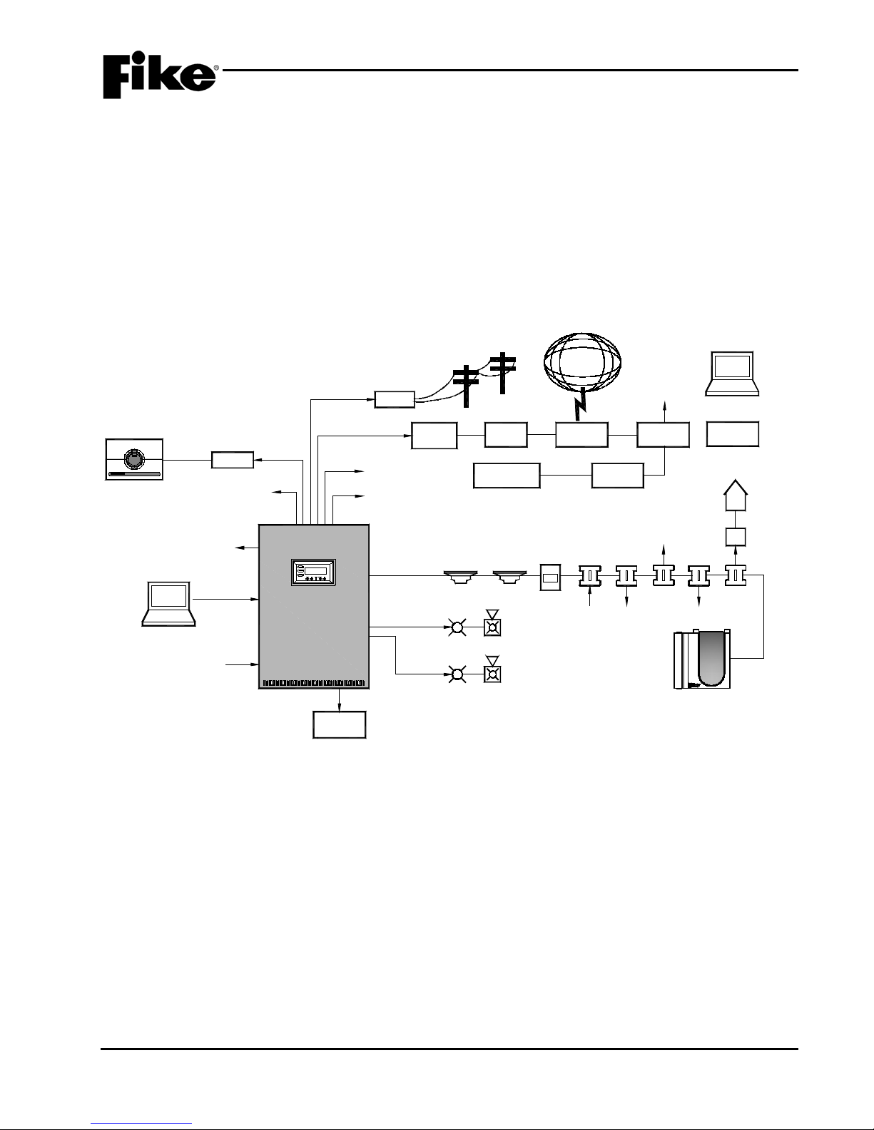
2.1 SYSTEM DESCRIPTION
The Fike Cheetah Xi 50 (P/N 10-071) is a state of the art, true addr essable peer-to-peer fire suppression
control system. It provi des the latest techno logy in detection com munication with extensi ve programmabilit y
in one cost effective s ystem. Its intelligenc e has every device c ommunicating as a peer on the sign aling line
circuit. This intelligenc e provides speed with respons e times as little as o ne-qua rter sec ond between m anual
pull station activation to notification appliance sounding.
Its flexibility provides you the freedom to attach the devices you require for your specific installation. The
Cheetah Xi 50 is equipped with one signaling line circuit capable of communicating with 50 addressable
devices in any combination.
UL S2203 Cheetah Xi 50 Installation Manual 2-1
FM P/N: 06-369 Rev 6, 09/2015
Exhibit 2-1: Cheetah Xi 50 Block Diagram
Page 14

2.0 SYSTEM OVERVIEW
2.1.1 CHEETAH Xi 50 FEATURES
GENERAL
♦ Two 24V DC, Class A or B, 1.75A NAC (audible) circuits on main board with integrated synchronization
♦ Two configurable relays and one Trouble relay
♦ 253 user defined zones
♦ 80 character, backlit LCD display
♦ Real time clock
♦ 3200 event history buffer
♦ Critical process monitoring
♦ One-person Walk Test capability
♦ Disable by point/circuit or zone
♦ Drill function at panel and remote
♦ Provides solenoid releasing operation
♦ Alarm verification
♦ Easy to add/remove devices
♦ Diagnostic menus
♦ Local piezo with distinct event tones
♦ 10 Status LEDs to easily identify system status
♦ Available with and without integral SERIAL, Point ID DACT interface
♦ Supports up to 31 peripheral devices
POWER
♦ 24V DC power supply; 5.25 amps useable alarm power, 2A standby
♦ Operation from 120VAC/ 60 Hz or 240VAC 50 /60Hz
♦ Two 24V DC, 1.75A continuous auxiliary power outputs
♦ Supports up to 75 AH of batteries
SIGNALING LINE CIRCUIT
♦ Address devices with Infrared (IR) tool, similar to remote control device (non-listed).
♦ One addressable loop, 50 d ev ices per loop
♦ NFPA Class A, B, or X with isolator devices
♦ True peer-to-peer digital protocol for extremely fast and reliable communications
♦ Addressable Device “learn” and “auto-program” fun ctio ns
♦ Automatic day/night sensitivity adjustment
♦ Automatic holiday sensitivity adjustment
♦ New Acclimate operation for detectors
♦ IR Tool provides ability to read sensitivity levels or perform remote test of device
♦ Devices contain multi-color LED for quick reference of device status
♦ Detectors provide early warning pre-alarm detection and can also provide a summing feature for up to 8 detectors
(non-listed).
♦ Sounder or Relay Bases fully programmable
♦ Optional Remote LED can be added to a detector base, programmable for any device, zone/state
ENCLOSURE
♦ 18 gauge steel enclosure with Red or Black finish
♦ Enclosures are equipped with a 0.50” wide lip to facilitate flush mounting
♦ Removable exterior door for e ase of insta lla tion
♦ Internal dead-front door option available
2-2 Cheetah Xi 50 Installation Manual UL S2203
Rev 6, 09/2015 P/N: 06-369 FM
Page 15

2.0 SYSTEM OVERVIEW
2.1.2 LISTINGS AND APPROVALS
Approval Agency File Number
Underwriters Laboratories S2203
Type: Local, Remote Station (PPU), Central Station (PPU)
Service Type: A-Automatic Fire Alarm, M-Manual Fire Alarm, Releasing Device
Service, WF-Water-flow alarm, SS-Sprinkler Supervisory Service,
DACT
Type Signaling: Non-coded
Factory Mutual (FM) Approved
California State Fire Marshall (CSFM) 7165-0900:149
City of New York (COA) #6119
City of Denver Approved
2.1.3 AGENCY STANDARDS AND COMPLIANCE
This Fire Alarm Control Panel complies with the following NFPA and UL standards:
NFPA 72 – National Fire Alarm Code
UL 864 – Standard for Control Units and Accessories for Fire Alarm Systems
UL 2017 – General Purpose Signaling Devices and Systems
The installer should also be familiar with the following documents and standards:
National Fire Protection Association (NFPA) Codes:
NFPA 12 - Carbon Dioxide Extinguishing Systems
NFPA 12A - Halon Fire Extinguishing Systems
NFPA 13 – Sprinkler Systems
NFPA 15 – W ater Spra y Fixed Systems
NFPA 16 – Deluge, Foam-water and Foam-water Spray Systems
NFPA 70 – National Electrical Code (NEC)
NFPA 70 - Article 300 – Wiring Methods
NFPA 70 - Article 760 – Fire Protective Sign al ing S ystems
NFPA 72 – National Fire Alarm and Signaling Code
NFPA 101 – Life Saf et y Code
NFPA 110 – Em er gency Standby Power Systems
NFPA 750 - Standard on Water Mist Fire Protection Systems
NFPA 2001 - Clean Agent Extinguis hin g S ystems
Underwriters Laboratories (UL) Standards:
UL 38 – Manually Actuated Signaling Boxes
UL 217 – Smoke Detectors, Single and Multiple Station
UL 228 – Door Closers – Holders for Fire Protective Signaling Systems
UL 268 – Smoke Detectors for Fire Protective Signaling Systems
UL 268A – Smoke Detectors for Duct Applications
UL 346 – Waterflow Indicators for Fire Protective Signaling Systems
UL 464 – Audible Signaling Appliances
UL 521 – Heat Detectors for Fire Protective Signaling Systems
UL 1481 – Power Supplies for Fire Protective Signaling Systems
UL 1638 – Visual Signaling Appliances
UL 1971 – Visual Signaling Appliances
Factory Mutual (FM) Standards:
FMRC 1011 and 1012 – Deluge and Pre-action Sprinkler Systems
Applicable Local and State Building Codes
Requirements of the Local Authority Having Jurisdiction
UL S2203 Cheetah Xi 50 Installation Manual 2-3
FM P/N: 06-369 Rev 6, 09/2015
Page 16
2.0 SYSTEM OVERVIEW
Protected Premises
(Local)
Station (PPU)
Part Number
Description
10-2622
Cheetah Xi 50 Controller
Y Y Y Y Y
Y
02-10881 (Note 1)
120VAC Primary Transformer
Y Y Y Y Y
Y
02-10882 (Note 1)
240VAC Primary Transformer
O O O O Y
Y
10-2528 (Note 2)
5-Zone DACT (Bosch FPT-DACT-LC), internal
O Y Y O Y
Y
10-2646
14 Button Remote Display (Exp. Protocol)
O O O O Y
Y
10-2631
10 Button Remote Display (Exp. Protocol)
O O O O Y
Y
68-023
VESDA Open Protocol High Level Interface (HLI)
O O O O Y
Y
10-2627
Ethernet Module
O O O O Y
Y
10-1XX
Intelligent LED Graphic Annunciator
O O O O Y Y 10-2667
20-Zone Remote Annunciator
O O O O Y
Y
10-2792 (Note 3)
Class A Peripheral Bus Card
O O O O Y
Y
10-2204 (Note 4)
CRM4 Relay Module
O O O O Y Y 10-2770 (Note 4)
HPM4 Relay Module
O O O O Y Y 10-2777
Relay Control Assembly
O O O O Y
Y
10-2780
Remote Equipment Enclosure, 3 Card
O O O O Y
Y
10-2781
Remote Equipment Enclosure, 5 Card
O O O O Y
Y
10-2236
Battery Enclosure, 75 AH maximum
O O O O Y
Y
Notes:
1. Only one transformer (120VAC or 240VAC) can be used.
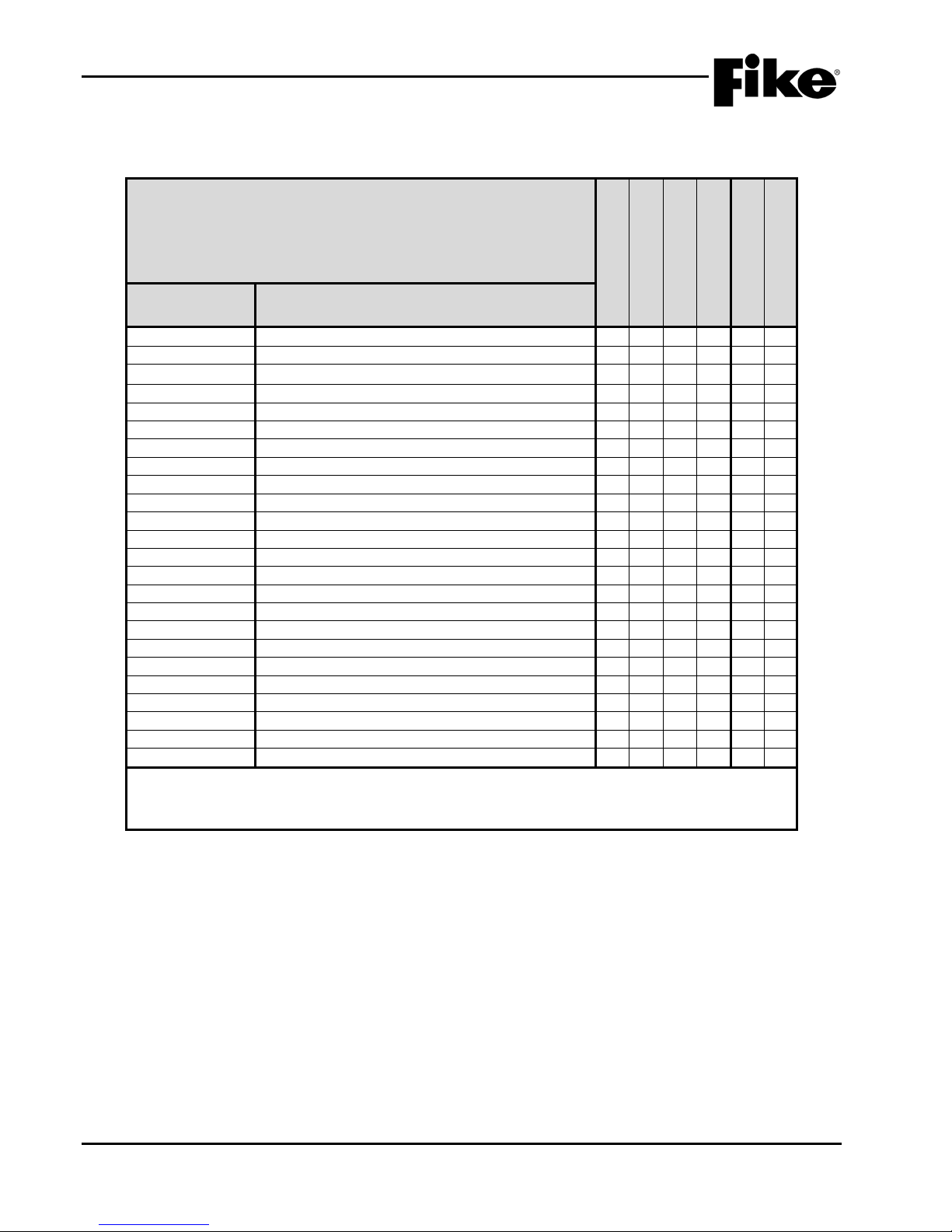
2.1.4 MINIMUM SYSTEM CONFIGURATIONS
Exhibit 2-2: MINIMUM SYSTEM CONFIGURATIONS
This table indicates the minimum components needed to meet the intended
applications.
Y = Yes
N = No
O = Optional
10-2623 Cheetah Xi 50 Enclosures Y Y Y Y Y Y
10-2628 Dead Front Panel O O O O Y Y
10-2476 (Note 2) 5-Zone DACT (Bosch FPT-DACT), external O O O O Y Y
10-2630 2 Button Remote Display (Exp. Protocol) O O O O Y Y
Central Station (PPU)
Remote Supervising
Releasing Service
UL Listed
FM Approved
10-2583 Multi-Interface Module O O O O Y Y
10-2785 Relay Card O O O O Y Y
10-2154 Battery Enclosure, 33 AH maximum O O O O Y Y
2. DACT must be purchased from Fike for proper operation with the Cheetah Xi 50 panel.
3. Included in the Class A Peripheral Bus Assembly (P/N 10-080).
4. Mounts to relay control assembly only. Cannot mount to Cheetah Xi 50 controller.
2-4 Cheetah Xi 50 Installation Manual UL S2203
Rev 6, 09/2015 P/N: 06-369 FM
Page 17
2.0 SYSTEM OVERVIEW
Remote Supervising
Part Number
Description
63-1052
Photoelectric Detector
O O O O Y
Y
67-033
Ionization Detector
O O O O Y
Y
67-034
Ionization Detector, Isolator Version
O O O O Y
Y
63-1053
Combination Photo/135°F Heat Detector
O O O O Y
Y
63-1059
Combination Photo/135°F Heat Detector, Isolator Version
O O O O Y
Y
60-1039
Heat Detector, 135°F-190°F (57-88°C) FT/RR
O O O O Y
Y
60-1040
Heat Detector, 135°F-190°F (57-88°C) FT/RR, Isolator
O O O O Y
Y
63-1060 (EBFI)
Detector Base , 6-inch, Isolat or Version
O O O O Y
Y
63-1055 (EB)
Detector Base , 4-inch
O O O O Y
Y
63-1064 (EBS)
Sounder Base, 6-inch
O O O O Y
Y
63-1063 (EBR)
Relay Base, 6-inch
O O O O Y
Y
55-045 (Note 1)
MMM – Mini Monitor Module
O O O Y Y
Y
55-050 (Note 1)
MMM – Mini Monitor Module, Isolator Version
O O O Y Y
Y
55-041 (Note 1)
MM – Monitor Module 4-inch
O O O Y Y
Y
55-046 (Note 1)
MM – Monitor Module 4-inch, Isolator Version
O O O Y Y
Y
20-1064
APS – Addressable Pull Station, Isolator Version
O O O O Y
Y
55-052
RCM – Releasing Control Module
O O O O Y
Y
55-042
SCM – Supervised Control Module
O O O Y Y
Y
55-047
SCM – Supervised Control Module, Isolator Version
O O O Y Y
Y
10-2360
Series Solenoid Diode/Resistor
O O O Y Y
Y
10-2413
Masterbox Interface
O O O O Y
Y
55-043
RM – Relay Module
O O O O Y
Y
55-048
RM – Relay Module, Isolator Version
O O O O Y
Y
63-1062
Photo Duct Detector, Isolator Version
O O O O Y
Y
63-1158
Duct Detector Housing (isolator base)
O O O O Y
Y
68-302
FAAST XT Aspirating Smoke Detector
O O O O Y
Y
Notes:
1. Module is required to monitor sprinkler syst em components (e.g., Waterf l ow, Tam per, Low Air, etc.).
Exhibit 2-3: MINIMUM SYSTEM CONFIGURATIONS – CONT.
This table indicates the minimum components needed to meet the intended
applications.
Y = Yes
N = No
O = Optional
Protected Premises
(Local)
Central Station (PPU)
Station (PPU)
Releasing Service
UL Listed
FM Approved
63-1058 Photoelectric Detector, Isolator Version O O O O Y Y
63-1054 (EBF) Detector Base , 6-inch O O O O Y Y
63-1061 (EBI) Detector Base , 4-inch, Isolat or Version O O O O Y Y
20-1063 APS – Addressable Pull Station O O O O Y Y
55-053 RCM – Releasing Control Module, Isolator Version O O O O Y Y
63-1057 Photo Duct Detector O O O O Y Y
68-140 FAAST Aspirating Smoke Detector O O O O Y Y
UL S2203 Cheetah Xi 50 Installation Manual 2-5
FM P/N: 06-369 Rev 6, 09/2015
Page 18

2.0 SYSTEM OVERVIEW
Reserved for future use.
2-6 Cheetah Xi 50 Installation Manual UL S2203
Rev 6, 09/2015 P/N: 06-369 FM
Page 19
3.0 SYSTEM COMPONENTS
Cheetah Xi 50
10-071-c-p-d
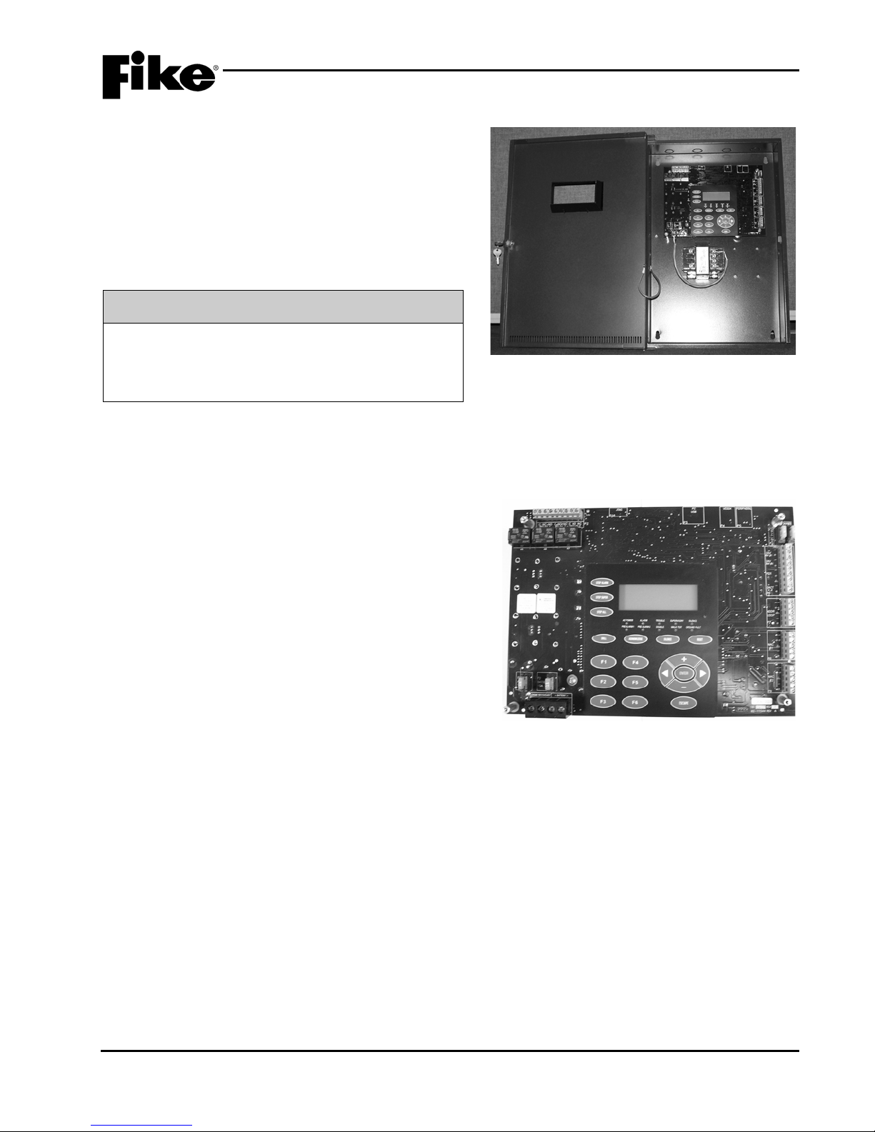
Exhibit 3-3: Cheetah Xi 50 Controller
3.1 BASIC EQUIPMENT PACKAGES
The Cheetah Xi 50 system includes the equipment
enclosure, control board, power transformer, and
necessary mounting hardware. Components such as
the cab inet color, transformer power requirements, and
cabinet requirem ents are custom configured to suit your
specific project requirements. Exhibit 3-2 shows the
available ordering options for the Cheetah Xi 50
equipment packages.
Enclosure Color c:
Transformer Power p:
Enclosure Options d:
R = Red, B = Black
1 = 120V, 2 = 240V
d = enclosure with dead-front
panel
Exhibit 3-1: Cheetah Xi 50 System Package
Exhibit 3-2: System Ordering Formats
Additional system components such as batteries, detector s, modules , cards, peripher al devic es, etc. m ust be
ordered separately to suit your specific project requirements.
3.2 CHEETAH Xi 50 CONTROLLER
The heart of the Cheetah Xi 50 system is the controller
(See Exhibit 3-3). The system controller consists of a
printed circuit board (PC B) that incorporates the s ystem
primary power supply with battery charger, system
microprocessors, hardware interface terminals, system
display and operational switches. The controller is the
central hub for communication between the systems
intelligent, addressab le field devices that are connect ed
to the panel’s signaling line circuits. The controller is
also used for system timing, user interface, power
delivery and system history archive.
UL S2203 Cheetah Xi 50 Installation Manual 3-1
FM P/N: 06-369 Rev 6, 09/2015
Page 20
3.0 SYSTEM COMPONENTS
K5 K6
K7
JTAG
P10
24V
P5
P4
AUX#1 F4 4A
P3
P2
10-2620 REV
02-11544 REV A
F1
F2
F3 F6
F5
F4
P10 P3 P4
P5
P2
P6
P7
P8
P9
P1
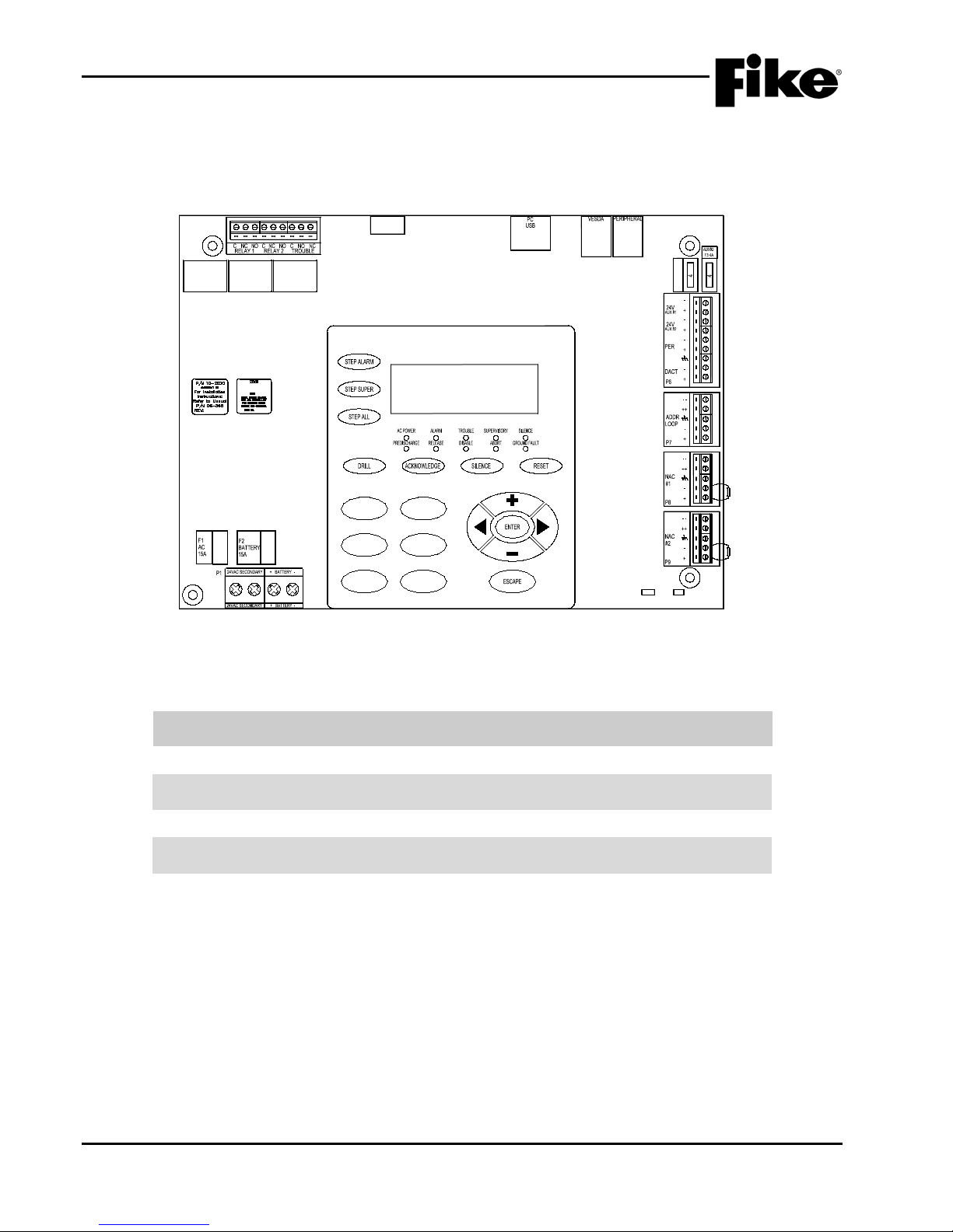
Exhibit 3-4: Cheetah Xi 50 Terminal Block Locations
Exhibit 3-4 shows the loc ation of the vari ous connec tors on t he Cheetah Xi 50 controller board. T he func tion
and specifications for each connection is listed in order of terminal block designation (P) on the following
pages.
Controller Specifications:
Controller Dimensions (HxWxD): 8 in. x 11 in. x 3 in.
(20.3 cm x 27.9 cm x 7.6 cm)
Weight: 1.0 lbs. (0.45 kg.)
Power Output: 2 Amps (Normal Standby)
5.25 Amps (Alarm)
Power Consumption: 116 mA (Normal Standby)
Operating Environm ent: +32°-120°F (0°-49°C)
93% relative humidity
3-2 Cheetah Xi 50 Installation Manual UL S2203
Rev 6, 09/2015 P/N: 06-369 FM
Page 21

3.0 SYSTEM COMPONENTS
Terminal
Block
Terminal
Labels
Function and Electrical
Ratings/Requirements
Wiring Requirements
P1
24VAC
• 120 VAC Transformer, P/N 02-10881
16 AWG THHN wiring minimum
a dedicated circuit at the main building
power distribution center. The circuit
ped with a lockout
I
It is critical that AC line
power is applied to the left terminals of P1
and not the battery terminals. Doing so
could cause damage to the controller.
Battery
• 24 VDC nominal standby battery input
• Non-power-limited and supervised
Batteries larger than 18 AH must be
P2
Alarm
• Terminals C, NC, NO
• Default alarm operation (configurable)
All connections shall be power-limited or
Supervisory
• Terminals C, NC, NO
(configurable)
All connections shall be power-limited or
Trouble
• Terminals C, NO, NC
• Default trouble operation
All connections shall be power-limited or
P3
PC USB
• RS232 port, power-limited and
present on the controller
Use communication cable P/N 10-1874A or
Exhibit 3-5: Cheetah Xi 50 Controller Terminal Specifications
Secondary
(+ -)
(Relay 1)
2.22 Amps @ 225 VA
• 240 VAC Transformer, P/N 02-10882
1.45 Amps @ 348 VA
• Fused by F1, 15A field replaceable fuse,
P/N 02-4174
• Non-power-limited and supervised
(Two 12 VDC batteries, sealed lead acid
only)
• 75 amp-hour maximum charging capacity
• 4 Amps @ 27 VDC max. charge current
• 12 Amps @ 27 VDC max. supply current
• Fused by F2, 15A field replaceable fuse,
P/N 02-4174
• SPDT Form C relay contact
• DC Operation: 5 amps @ 30 VDC (pf-.35)
• AC Operation: 0.5 amps @ 120 VAC
(pf=.35)
Terminal block accepts 12 AWG – 16 AWG
wire
System AC Line power must originate from
breaker shall be equip
mechanism and be clearly labeled as a “Fire
Alarm.”
CAUTION:
mounted in external battery enclosure.
Use 14 AWG minimum wire (max. length of
10 ft. [3m] to connect batteries to controller)
non-power-limited, not both
(Relay 2)
UL S2203 Cheetah Xi 50 Installation Manual 3-3
FM P/N: 06-369 Rev 6, 09/2015
(Relay 3)
• SPDT Form C relay contact
• DC Operation: 2 amps @ 30 VDC (pf-.35)
• AC Operation: 0.5 amps @ 120 VAC
(pf=.35)
• Default supervisory operation
• SPDT Form C relay contact
• DC Operation: 2 amps @ 30 VDC (pf-.35)
• AC Operation: 0.5 amps @ 120 VAC
(pf=.35)
supervised
• Used for panel programming, peripheral
device configuration, and data retrieval
using C-Linx software
• Not intended for continuous connection
• Do not connect the PC if a ground fault is
non-power-limited, not both
non-power-limited, not both
Relay contacts are normally energized and
contacts are shown with power applied and
no troubles present on the system.
B to connect programming computer to P3
50 ft. (15m) maximum cable length.
PC communication: 19200 Baud, 8 data
bits, no parity, 1 stop bit
Page 22

3.0 SYSTEM COMPONENTS
Terminal
Block
Terminal
Labels
Function and Electrical
Ratings/Requirements
Wiring Requirements
P4
VESDA
• RS232 port, power-limited and
Does not require SLC address
68-023 includes 14 ft. (4.27m) RS232 cable
P5
PERIPHERAL
(232)
P6
DACT
• Power-limited and supervised
or external in a separate enclosure
Terminal blocks accept 12 – 24 AWG
PERipherals
• Power-limited and supervised
RS485 wiring: Belden 9841 or equal. Use
Terminal blocks accept 12 – 24 AWG
24V AUX
• Power-limited and supervised
VDC for operation
The Cheetah Xi 50 controller has a total
P7
ADDR LOOP
• Power-limited and supervised
Sprinkler operation requires that initiating
device circuits be Class A and wired to
FM Listed/Approved devices.
12,000 ft. (3657m) maximum wire length
Exhibit 3-6: Cheetah Xi 50 Controller Terminal Speci ficat ion s – Cont.
(+ -)
(485)
(shld,+ , -)
supervised
• VESDA High Level Interface (HLI) P/N
68-023 connection point
• Intelligently links Xtralis VESDA detectors
to the Cheetah Xi 50 by zone #, 0 – 255.
• Currently not used.
• Interface point for Digital Alarm
Communicator Transmitter (Point ID
communication)
• DACT can be mounted inside t he panel
• Connects to RS485 peripheral devices
• 31 peripheral devices maximum
• Typical circuit voltage will vary between 0
– 1 VDC. It should never be a constant
voltage or 0 VDC
• Peripheral devices must be configured as
supervised if 2-way communication is
required
P/N 02-3053 for connection to the Cheetah
Xi 50 controller P4
HLI must be powered from the Cheetah Xi
50 auxiliary power outputs or a ground fault
condition could occur
Belden 82841, 82842, or 89841 for plenum
applications
Maximum wire length of 4000 ft. (1219m),
9600 bps, 5 VDC, 1mA
Maximum wire impedance 110Ω
Maximum wire capacitance 0.05uF
100Ω termination resistor is required on the
last device on circuit, P/N 02-2519 (supplied
with each device)
T-tapping of circuit is NOT allowed
#1 and #2
(+, -, shld)
• Regulated auxiliary power output rated 24
VDC @ 1.75A maximum, regulated 28
volts maximum
• Fused by F3 and F4 for short circuit, 4A
field replaceable fuse, P/N 02-11412
• Used to power detectors, peripheral
devices, modules, etc. that require 24
(+, -, shld, -,
+)
• Supports up to 50 addressable dev ices
(only those listed in this manual)
• Support Class B, Class A or Class X if
using isolator devices
• Maximum loop current draw: 50 mA @
28 VDC
• Typical circuit voltage will range from 24
VDC nominal to 0 – 5 VDC during data
communication pulse. It should never be
a constant 0 VDC
• FM Approved Deluge and Pre-action
3-4 Cheetah Xi 50 Installation Manual UL S2203
Rev 6, 09/2015 P/N: 06-369 FM
power capability of 6 amps. The Cheetah Xi
1016 is expandable to 12 amps with the
addition of the 10-2474, Supplemental
Power Supply
Terminal blocks accept 12 – 24 AWG
from panel to last device using 14 AWG
Shielded cable should be used for
electrically noisy environments
Maximum resistance 70Ω (35Ω per leg)
Maximum capacitance 0.60uF
If using Class X wiring, the first and last
isolator device shall be mounted within
conduit, within the same room as the control
panel, and no more than 20 ft. (6.1m) from
the control panel
Terminal blocks accept 12 – 24 AWG
Page 23
3.0 SYSTEM COMPONENTS
Terminal
Block
Terminal
Labels
Function and Electrical
Ratings/Requirements
Wiring Requirements
P8 & P9
NAC #1 & #2
• Power-limited and supervised
simultaneously.
T-tapping of circuit is NOT allowed
P10
JTAG
• Fike use only
P11
• Fike use only
Exhibit 3-8: NAC Circuit Field Wiring Resistance
Exhibit 3-7: Cheetah Xi 50 Controller Terminal Speci ficat ion s – Cont.
(--, ++, shld, -,
+)
• Continuous, regulated 24 VDC @ 1.75A
maximum, regulated 28 volts maximum
• Supports Class B using 1.2KΩ EOL
resistor, P/N 10-2570 or Class A using
redundant wiring
• Can be programmed for Gentex or
System Sensor synchronization
protocols.
• Once sync is selected, programmable for
selective silence (strobes remain ON) or
silence both horn and strobe
If using the synchronization protocol option,
both circuits must use the same protocol
(i.e. Gentex or System Sensor)
The circuits are either ON or OFF and can
not be configured for modulation patterns.
Refer to Fike document 06-186,
“Compatible Notification Appliances and
Releasing Devices Manual” for a list of
compatible NAC devices
Terminal blocks accept 12 – 24 AWG
3.2.1 NAC CIRCUIT LIMITATIONS
The NAC circ uit field wiring resis tance is limited by the amount of anticipated load. Many local authorities
require a voltage drop ca lculation be performed to de monstrate the lo west voltage pr esent at the las t device.
The designer shall determine the resistance of the wire specified and distance for the installation needs.
From this information, they can determine the total resistance for the circuit. Exhibit 3-8 provides the
maximum field wiring resistance for total device current that can also be used as a tool.
Max Current (Amps) .1 .2 .3 .4 .5 .6 .8 1.0 1.5 2.0
Audible Max Ω’s 24 12 8 6 4.8 4.0 3.0 2.4 1.6 1.2
3.2.2 CONTROLLER TEST POINTS/VOLTAGES
The Cheetah Xi 50 controller has two primary test points . While viewing the panel disp lay, TP1 is located in
the lower right corner of the board t o the r ight of the boar d part num ber . TP2 is lo cated jus t to the r ight of the
relay block in the upper left corner of the board and is labeled 24V.
TP1 = COM
This test point should be used when making DC vo ltage measurements on the c ontrol board. Connect the
voltmeter ground lead to thi s point, a nd the n touc h the positive lead to the point under tes t. T his is the gr ound
reference for all points on the control board.
TP2 = 24V
This test point is the + side for the main controller 24VDC power buss. If the system does not seem to
operate properly even with AC power applied, connect the voltmeter positive lead to this point , and then
touch the ground lead to test point TP1 to verify the board voltage.
Ground Fault, TP1 to Chassis
With a normal pan el and no ground fault, this voltage is 2.17 VDC nom inal for Level 1 ground fault, and 5
VDC nominal for Level 2 ground f ault. If a ground fault is present, this voltage w ill sway in either direction.
Ground fault detection impedances are 60K ohm between power ground and chassis ground or 1M ohm
between main power and chassis ground.
UL S2203 Cheetah Xi 50 Installation Manual 3-5
FM P/N: 06-369 Rev 6, 09/2015
Page 24

3.0 SYSTEM COMPONENTS
Cheetah Xi 50
10-2623-c-d
3.3 SYSTEM ENCLOSURE
The Cheetah Xi 50 system enclosure is designed to allow mounting of the control board, AC power
transformer, optional DACT, up to two 18 AH batteries, as well as one of the following optional cards an d
modules as required to suit your specific project requirements:
• Ethernet Module, P/N 10-2627
• Multi-Interface Module, P/N 10-2583
• Class A Peripheral Bus Card, P/N 10-2792
• Masterbox Interface, P/N 10-2413
The enclosure can be ordered as part of the bas ic equipm ent package as show n in Exhibit 3-2 or separat ely
as shown in Exhibit 3-9.
Typical Enclosure Features
• Made of 18 gauge steel with baked on Red or Black enamel finish.
• Each enclosure is suitable for surface or flush mounting.
• Numerous conduit knockouts are provided in the back box for easy access to the cabinet during
system installation.
• Press-studs supplied in enclos ure bac k -box f or eas y instal lation of s ystem components (i.e. , Cheetah
Xi 50 control board, transformer, DACT, etc.).
• The removable exterior door mount s on the left side of the c abinet only and is equipped with a key-
lock and display viewing window. Door opens a full 180 degrees.
• Optional dead-front panel (P/N 10-2628) isolates the o perator fr om the interior el ectr onics an d wir ing,
yet can be easily removed to reveal system components for maintenance.
Enclosure Color c:
Enclosure Options d:
R = Red, B = Black
d = standard enclosure, with dead-front panel
Exhibit 3-9: Enclosure Ordering Format
Refer to Section 4.0 Installation, for complete dimensional specifications of the enclosure.
3-6 Cheetah Xi 50 Installation Manual UL S2203
Rev 6, 09/2015 P/N: 06-369 FM
Page 25
3.0 SYSTEM COMPONENTS
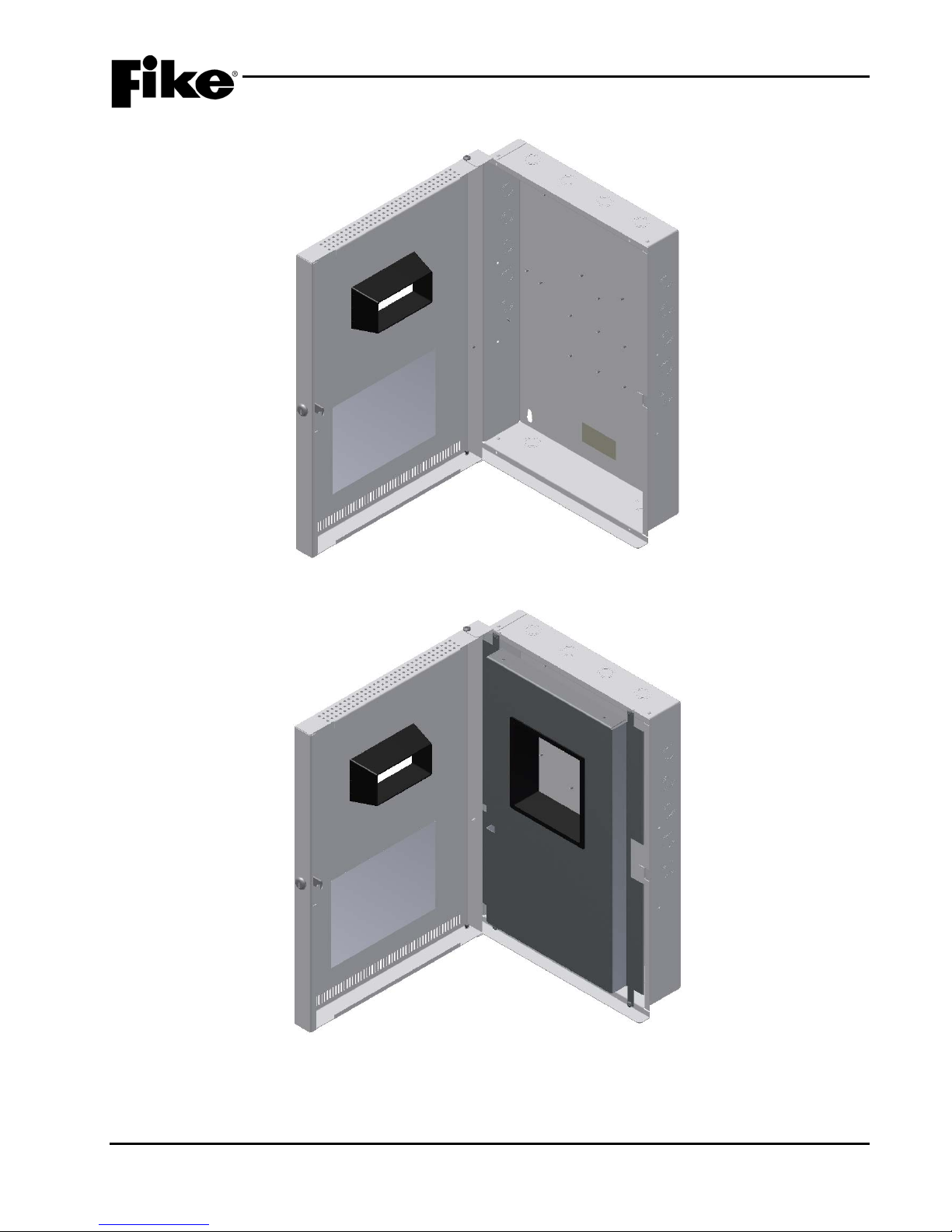
Exhibit 3-10: Cheetah Xi 50 Enclosure
Exhibit 3-11: Cheetah Xi 50 Enclosure with Dead-Front
Refer to Fike document 06-624 for enclosure installation instructions.
UL S2203 Cheetah Xi 50 Installation Manual 3-7
FM P/N: 06-369 Rev 6, 09/2015
Page 26
3.0 SYSTEM COMPONENTS
3.4 DIGITAL ALARM COMMUNICATOR TRANSMITTER (DACT)
DACT, 5 ZONE WITH SERIAL IN TERFACE
P/N 10-2528 (BOSCH FPT-DACT-LC), INTERNAL MOUNT
P/N 10-2476 (BOSCH FPT-DACT), EXTERNAL MOUNT
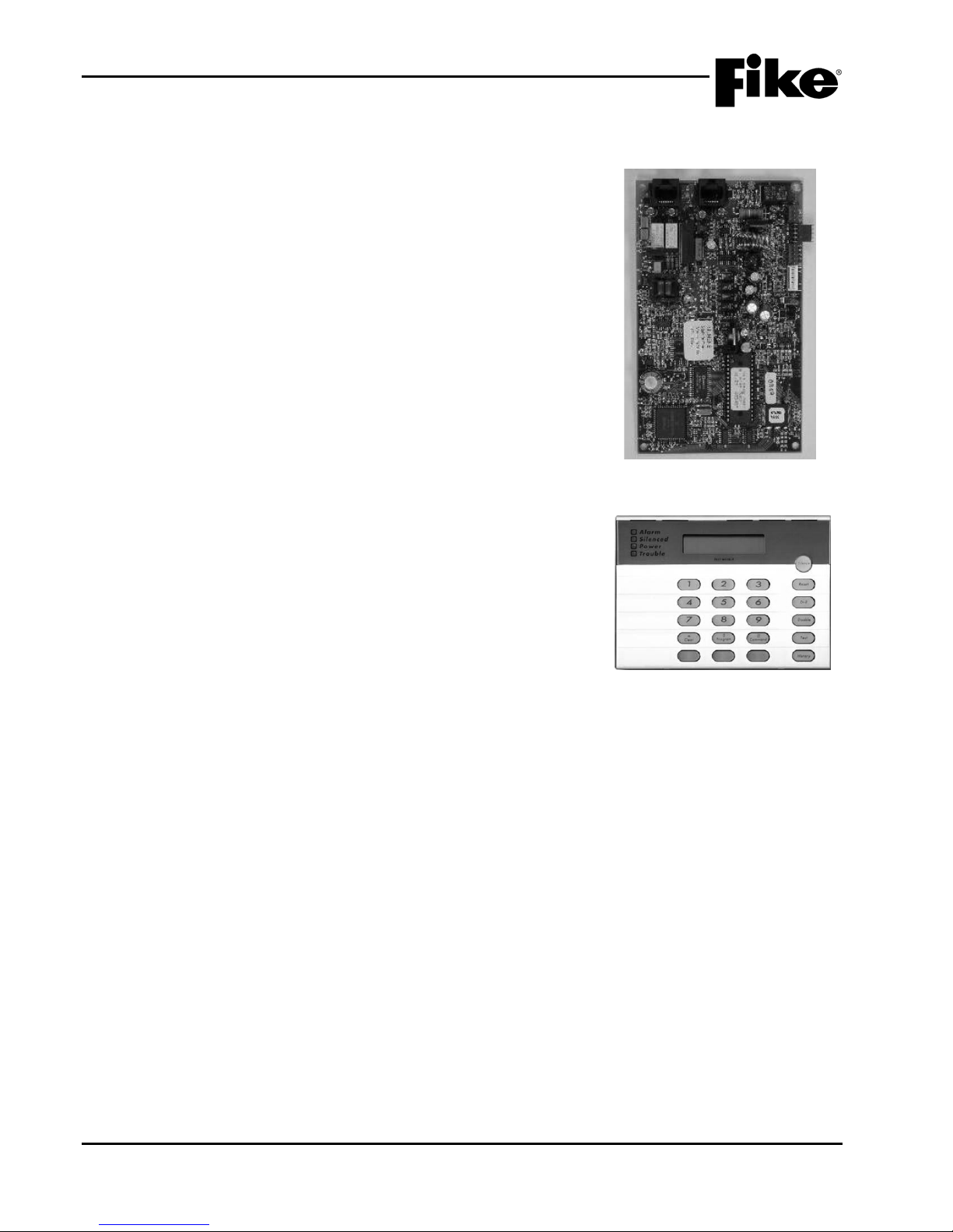
The Digital Alarm Communicator Transmitter (See Exhibit 3-12) is
used where point identification of alarm, supervisory and trouble
events is required at a Central or Remote Receiving Station. The
Cheetah Xi 50 transmits all system inf ormation to the DACT via an
RS485 connection. In addition, the DACT includes five
programmable point inputs that can be individually configured to
indicate seven types of system conditions: Fire Alarm, Waterflow
Alarm, Supervisory, Monitor Alarm, System Fault, AC Failure and
Low Battery. These inputs can be used in place of the intelligent
RS485 connection to provide simple alarm monitoring where the
receiving station is not capable of receiving point ID information.
Refer to Fike document 06-479 for more information.
3.4.1 DACT KEYPAD PROGRAMMER, P/N 10-2477 (BOSCH
FMR-DACT-KEYPAD)
Exhibit 3-12: DACT
This DACT Programmer (See Exhibit 3-13) is necess ary for
configuring the 10-2528 and 10-2476 dialers referenced
above.
Refer to BOSCH document FPT-DACT “Operation &
Installation Guide” for more information.
Exhibit 3-13: DACT Programmer
3-8 Cheetah Xi 50 Installation Manual UL S2203
Rev 6, 09/2015 P/N: 06-369 FM
Page 27
3.0 SYSTEM COMPONENTS
3.5 PERIHERAL BUS DEVICES
Several optional components can be installed on the Cheetah Xi 50 controller ’s RS485 peripheral bus (31
devices maximum ) to provide rem ote annunciation and control of system event s, and to ex pand the s ystems
operational capabilit ies. A br ief descr iption of eac h com ponent and its functiona lity is prov ided in t his sectio n
for reference purposes. For a complete description of each module’s functionality, installation and wiring,
refer to the referenced document.
Unless noted otherwise, all peripheral devices are mounted external to the Cheetah Xi 50 enclosure.
3.5.1 FOURTEEN BUTTON REMOTE DISPLAY UNIT,
P/N 10-2646
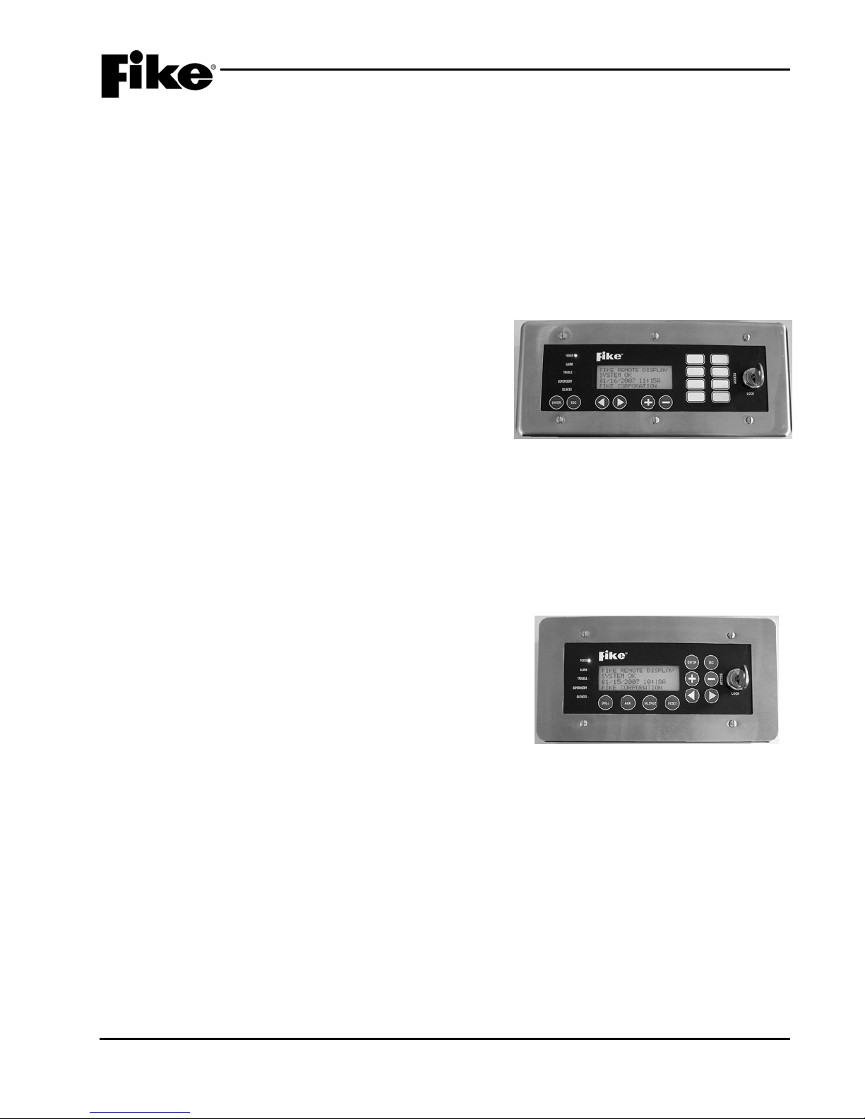
The Fourteen Button Rem ote Dis pla y Unit (See Exhi bit 3-14)
provides a 4x20 charac ter LCD that mim ics the host control
panel’s display. This allows s ystem status inform ation to be
displayed at a remote location. The unit is equipped with
eight programmable buttons that can be used to perform
system control functions such as Reset, Silence,
Acknowledge, etc. Switch functions are protected by the
unit’s integral secur ity access key. In addition, the RDU is
equipped with an internal piezo and five status LEDs that
provide instant audible and visual notification of system
status changes.
Refer to Fike document 06-610 for more information.
Exhibit 3-14: Fourteen Button
Remote Display Unit
Note: This unit can only be used on systems with
panel firmware V3.0 or higher.
3.5.2 TEN BUTTON REMOTE DISPLAY UNIT, P/N 10-2631
The Ten Button Remote Display Unit (See Exhibit 3-15) pr ovides
a 4x20 character LCD that mimics the host control panel’s
display. This allows s ystem s tatus inf ormation to be dis played at
a remote location. The unit is equipped with four control
switches that allow initiation of system Drill, Acknowledge,
Silence and Reset function s from the unit. Switch functions are
protected by the unit’s inte gral security access key. In additi on,
the RDU is equipped with an inter nal piezo and five s tatus LEDs
that provide instant audible and visual notification of system
status changes.
Refer to Fike document 06-610 for more information.
Note: This unit can only be used on systems with panel
firmware V3.0 or higher.
Exhibit 3-15: Ten Button
Remote Display Unit
UL S2203 Cheetah Xi 50 Installation Manual 3-9
FM P/N: 06-369 Rev 6, 09/2015
Page 28
3.0 SYSTEM COMPONENTS
3.5.3 TWO BUTTON REMOTE DISPLAY UNIT, P/N 10-2630
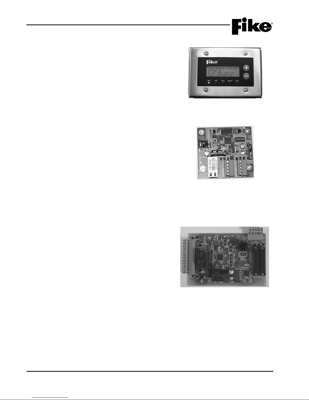
The Two Button Remote Display Unit (See Exhibit 3-16) provides
a 4x20 character LCD that mimics the host control panel’s
display. This allows s ystem s tatus inf ormation to be dis played at
a remote location. The unit is equipped with an internal piezo
and five status LEDs that provide instant audible and visual
notification of system status changes.
Refer to Fike document 06-610 for more information.
Note: This unit can only be used on systems with panel
firmware V3.0 or higher.
3.5.4 ETHERNET MODULE, P/N 10-2627
ETHERNET MODULE W/ ENCLOSURE, P/N 10-074
The Ethernet Module (See Exhibit 3-17) provides a means to
connect the associated control panel to the Ethernet
(LAN/WAN). This connection allows the associated control
panel to send its history events to a remote monitor i ng pane l th at
can be located either on or off the protected premises.
Exhibit 3-16: Two Button
Remote Display Unit
The module can be mounted insi de the Cheetah Xi 50 enclosure
or it can be mounted rem otely by ordering t he custom mounting
enclosure.
Refer to Fike document 06-388 for more information.
3.5.5 MULTI-INTERFACE MODULE, P/N 10-2583
MULTI-INTERFACE MODULE W/ ENCLOSURE,
P/N 10-069
The Multi-Interface Module (See Exhibit 3-18) provides an
interface point that allows connection of the following
ancillary devices to the host control panel:
1. Cheetah Classic panel – this interface allows the MIM
to act as a network card on the Cheetah Classic
network.
higher)
2. Parallel Printer – this interface allows a parallel printer
that is listed for “Fire Protective Signaling Use” to be
connected to the host control panel.
3. Serial Printer – this interface allows a Keltron 90-series
printer to be connected to the host control panel.
4. PC Graphic – this interface allows a PC Graphic
workstation to be connected to the host control panel.
(feature not available in V7.00 firmware and
Exhibit 3-17: Ethernet Module
Exhibit 3-18: Multi-Interface Module (MIM)
The module can be mounted inside the Cheetah Xi 50
enclosure or it can be mounted remotely by ordering the
custom mounting enclosure.
Refer to Fike document 06-367 for more information.
3-10 Cheetah Xi 50 Installation Manual UL S2203
Rev 6, 09/2015 P/N: 06-369 FM
Page 29
3.0 SYSTEM COMPONENTS
Zone Remote Annunciator
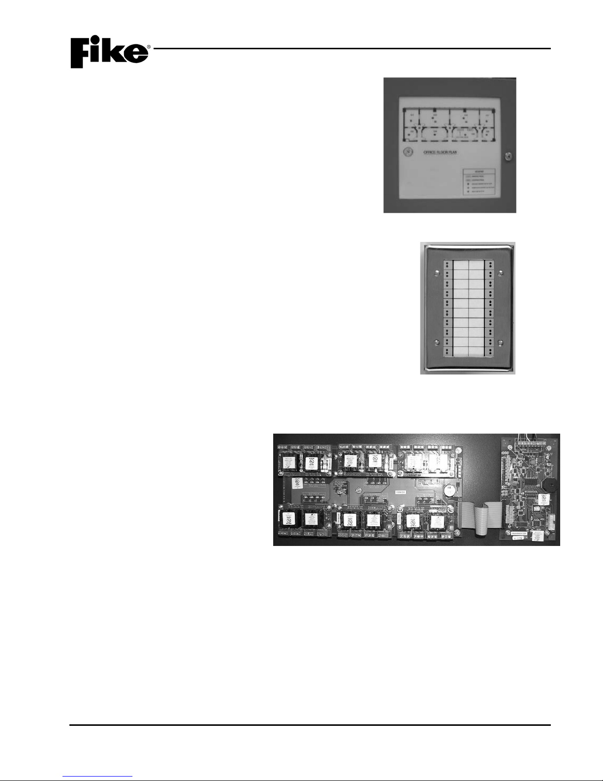
3.5.6 INTELLIGENT GRAPHIC ANNUNCIATOR
The LED Graphic (See Exhibit 3-19) is a custom made
graphic display that provides a specific building layout
pictorial with the actual fire alarm devices indicated with a
color status LED (red, green, yellow or orange). W hen an
event occurs, the intelligent data will be transferred via the
RS485 output to the graphi c and the specific device o r zone
LED will light as programmed.
Refer to Fike document 06-231 for more information.
Exhibit 3-19: LED Graphic Annunciator
3.5.7 TWENTY ZONE REMOTE ANNUNCIATOR, P/N 10-2667
The Twenty Zone Remote Annunciator (See Exhibit 3-20) is a
tabular based display equ ipped with 40 LEDs (twenty red and twenty
yellow). Each LED can be individually configured to annunciate the
status of the host control panel or an individual zone/state event.
Refer to Fike document 06-453 for more information.
3.5.8 RELAY CONTROL ASSEMBLY, P/N 10-2777
The Relay Control Assembly (See Exhibit
3-21) provides a m ounting location for up
to six (6) CRM4 (P/N 10-2204) and/or
HPM4 (P/N 10-2770) relay modules. This
configuration allows up to t wenty-four (24)
programmable relays to be added to the
system to provide system status
indication, control of electrical loads, or
general purpose switching.
The assembly includes the Relay Control
Card (P/N 10-2778), Bus Card (P/N 10-
2769), and Interface Cab le (P/N 10-2784).
The CRM4 and HPM4 relay modules are
ordered separately.
Refer to Fike document 06-580 and 06-443 for more information.
Note: The CRM4 and HPM4 relay cards are compatible with the Rela y Control As sembly only.
Exhibit 3-21: Relay Control Assembly
Exhibit 3-20: Twenty
UL S2203 Cheetah Xi 50 Installation Manual 3-11
FM P/N: 06-369 Rev 6, 09/2015
Page 30
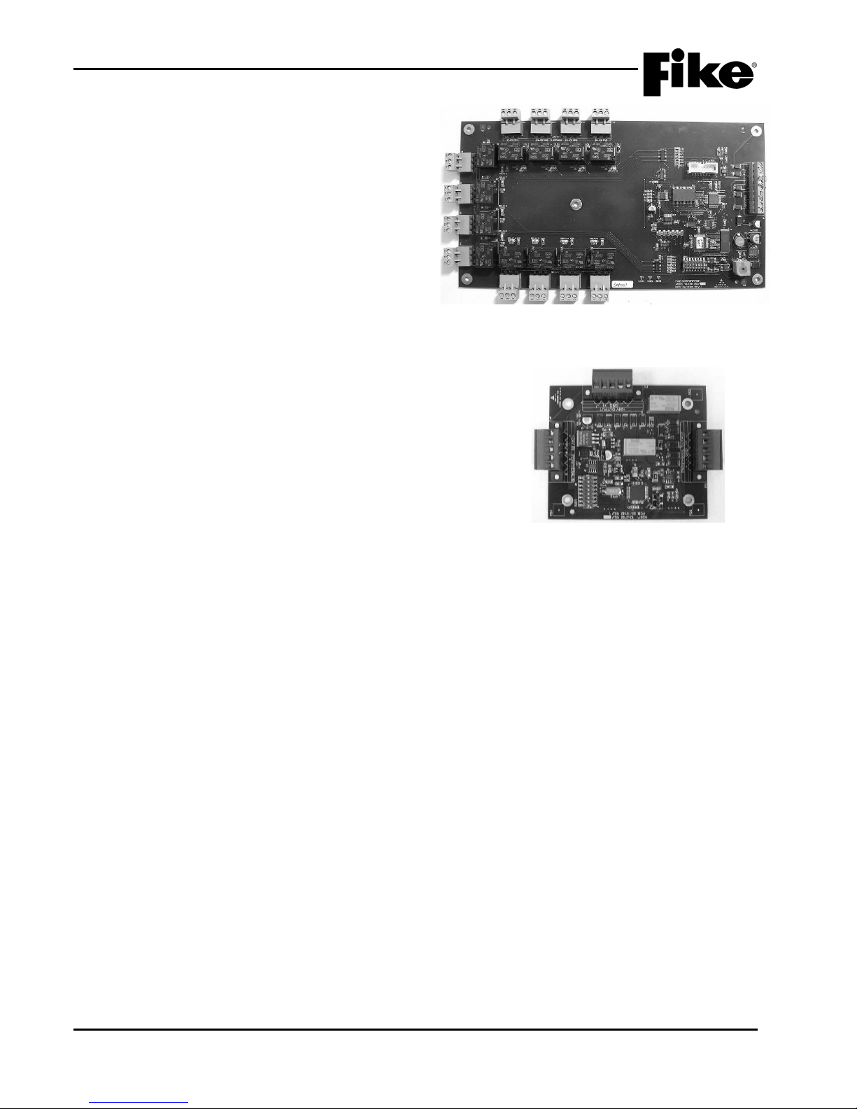
3.0 SYSTEM COMPONENTS
3.5.9 RELAY CARD, P/N 10-2785
The Relay Card (See Exhibit 3-22) provides twel ve
(12) programmable relays integrated into a single
card. When added to the s ystem, the relays can be
used to provide system status indication, control of
electrical loads, and general purpose switching.
Refer to Fike document 06-586 for more information.
3.5.10 CLASS A PERIPHERAL BUS CARD, P/N 10-2792
The Class A Peripheral Bus Card (See Exhibit 3-23)
provides a means of wiring the pan el’s RS48 5 per ipheral bus
and 24 VDC power output to the connected peripheral
devices in a Class A format.
The card can be mounted inside the Cheetah Xi 50
enclosure or it can be mounted remotely by ordering the
custom mounting enclosure.
Refer to Fike document 06-606 and 06-609 for more
information.
Exhibit 3-22: Relay Card
Exhibit 3-23: Class A Peripheral Bus Card
3-12 Cheetah Xi 50 Installation Manual UL S2203
Rev 6, 09/2015 P/N: 06-369 FM
Page 31
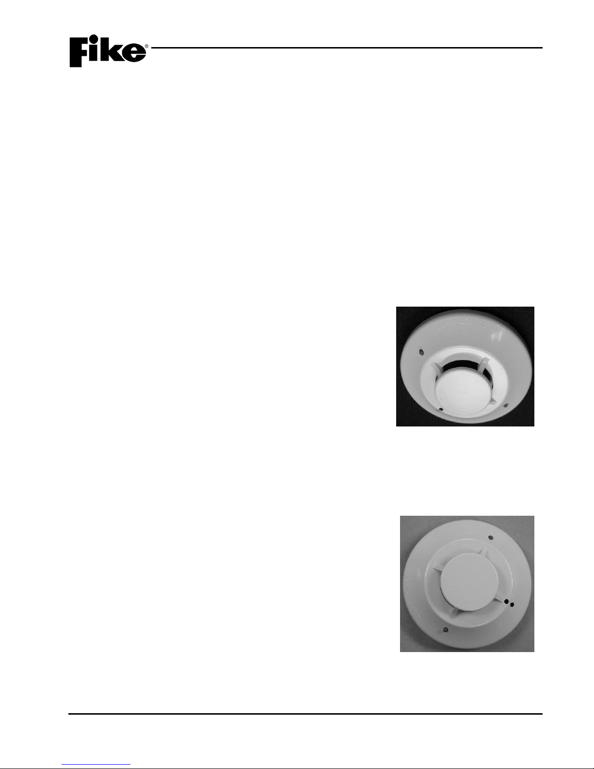
3.0 SYSTEM COMPONENTS
Alarm Verification
Drift Compensation
PreAlarm 1
Walktest
PreAlarm 2
Device Summing
Acclimate
Remote Annunciator
Day/Night Sensitivity
Alarm Verification
Drift Compensation
PreAlarm 1
Walktest
PreAlarm 2
Device Summing
Acclimate
Remote Annunciator
Day/Night Sensitivity
Smolder Enhance
3.6 INTELLIGENT DETECTORS
The Cheetah Xi 50 system uses intelligent detectors that not only include all necessary processing for
decision making but also include the control logic for the system, greatly reducing the importance of the
central controller. The ope rating param eters are downlo aded to the devic es during system configuration in to
nonvolatile memory.
The intelligent, addres sable detectors are con nected to and receive the ir operating power (15-30VDC) from
the host control panel via the panel’s signaling line circuit (SLC), which is capable of supporting up to 50
addressable devices i n any combination of detector s and modules. Each addr essable device is assigne d a
unique SLC address that a llows it to be iden tified not o nl y by the s ystem contr oller for device supervision, but
by other SLC devices as well to f ac ilit ate peer to peer system operation. A brief d es c riptio n of eac h intelligent
detector and its features is provided in this section for reference purposes.
Refer to Fike docum ent P/N 06-369-2, “Cheetah Xi 50 Operations Manua l” for details of detector operation
and available programming features.
Refer to installation and maintenance instructions supplied with each detector for more information.
Note: Detector electronics are rated 32° - 120°F (0° - 49°C), 10- 93% relative humidit y, unless otherwise
noted.
3.6.1 PHOTOELECTRIC SMOKE DETECTOR, P/N 63-1052
PHOTOELECTRIC SMOKE DETECTOR WITH
ISOLATOR, P/N 63-1058
The Photoelectric Smoke Detector (See Exhibit 3-24) is an
intelligent, spot-t ype smoke detector that utilizes th e l ight obs c uration
principle to detect smoke. The detector i ncludes a tri-color LED for
instant indication of device status. The isolator version provides
complete short circui t isolation for NFPA Class X wiring when us ed
with an isolator base.
The following modes of operation for the detector are configurable to
suit your specific project requirements:
3.6.2 IONIZATION SMOKE DETECTOR, P/N 67-033
IONIZATION DETECTOR WITH ISOLATOR, P/N 67-034
The Ionization Smoke Detector (See Exhibit 3-25) is an intelligent,
spot-type smoke detector that utilizes the ionization principle to
detect smoke. The detector includes a tri-color LED for instant
indication of device s tatus. The isolator version prov ides complete
short circuit isolation for NFPA Class X wiring when used with an
isolator base.
The following modes of operation for the detector are configurable to
suit your specific project requirements:
Exhibit 3-24: Photo Detector
UL S2203 Cheetah Xi 50 Installation Manual 3-13
FM P/N: 06-369 Rev 6, 09/2015
Exhibit 3-25: Ion Detector
Page 32
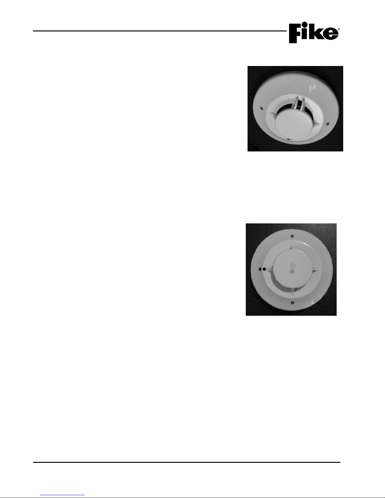
3.0 SYSTEM COMPONENTS
Alarm Verification
Drift Compensation
PreAlarm 1
Walktest
PreAlarm 2
Device Summing
Acclimate
Remote Annunciator
Day/Night Sensitivit y
Flame Enhance
Alarm Verification
Walktest
PreAlarm 1
Remote Annunciator
PreAlarm 2
Fixed Temp/Rate-of-Rise
Exhibit 3
Detector
3.6.3 PHOTO/HEAT COMBINATION DETECTOR, P/N 63-1053
PHOTO/HEAT DETECTOR WITH ISOLATOR, P/N 63-1059
The Photo/Heat Detector (See Exhibit 3-26) is an intelligent, spottype smoke detector that utilizes the light obscuration principle to
detect smoke. In addition to th e photoelectric sensing cham ber, the
detector is equipped with a thermistor bas ed, 135°F heat detection
circuit. The detector includes a tri-color LED for ins tant indication of
device status. The isolator version provides complete short circuit
isolation for NFPA Class X wiring when used with an isolator base.
The following modes of operation for the detector are configurable to
suit your specific project requirements:
Note: Photo element of detector can be programmed as
Supervisory and Heat element for Alarm.
-26: Photo/Heat
3.6.4 HEAT DETECTOR, P/N 60-1039
HEAT DETECTOR WITH ISOLATOR, P/N 60-1040
The Heat Detector (See Exhibit 3-27) is a spot-type detector,
designed to be programmable for a set-point range of 135-174°F
(57.2-78.9°C) for ordinary detection or 175-190°F (79.4-87.8°C) for
intermediate detection. Detectors in the ordinary range may be
programmed for either fixed temper ature or 15°F (9.4°C) r ate of rise
operation. Detectors in the intermediate range are Fixed
temperature only. The detection set-point is software programmable
in five degree increments from 135-190°F (57.2-87.8°C). The
detector includes a tri-color LED for instant indication of device
status. The isolator vers ion provides com plete short circuit isolatio n
for NFPA Class X wiring when used with an isolator base.
The following modes of operation for the detector are configurable to
suit your specific project requirements:
Exhibit 3-27: Heat Detector
3-14 Cheetah Xi 50 Installation Manual UL S2203
Rev 6, 09/2015 P/N: 06-369 FM
Page 33
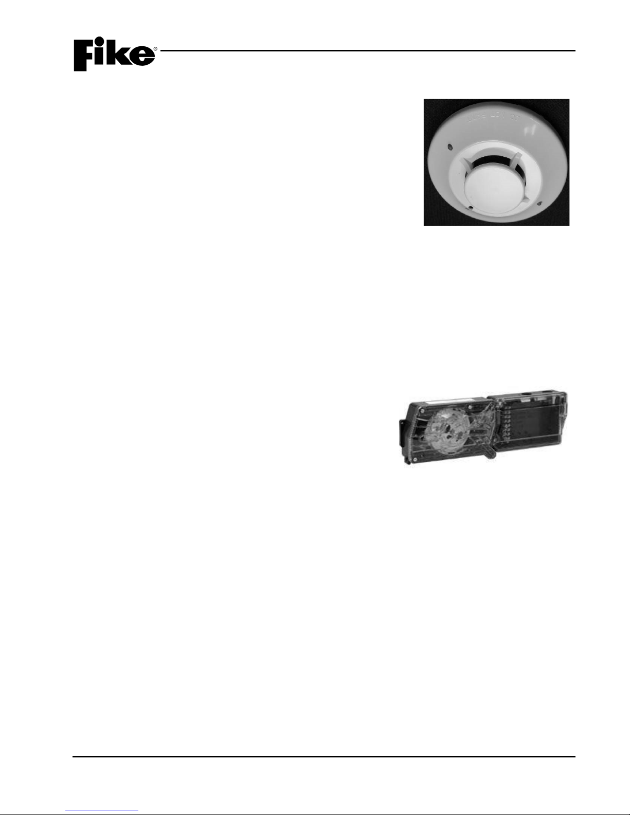
3.0 SYSTEM COMPONENTS
Alarm Verification
Drift Compensation
PreAlarm 1
Walktest
PreAlarm 2
Device Summing
Acclimate
Remote Annunciator
Day/Night Sensitivity
3.6.5 PHOTOELECTRIC DUCT DETECTOR, P/N 63-1057
PHOTOELECTRIC SMOKE DETECTOR WITH ISOLATOR,
P/N 63-1062
The Photoelectric Duc t Detector (See Exhibit 3-28) is an intelligent,
spot-type smoke detec tor that utilizes the light obsc uration principle
to detect smoke. The detector is designed for use inside the duct
detector housing only and should not be used for open area
applications. The detector includes a tri-color LED for instant
indication of device s tatus. The isolator version prov ides complete
short circuit isolation for NFPA Class X wiring when used with an
isolator base.
The following modes of operation for the detector are configurable to
suit your specific project requirements:
Note: Photo Duct Detector can be progr ammed as a Super visory
input as required by some Local Authority Having Jurisdictions
(AHJ).
Exhibit 3-28: Photo Duct Detector
3.6.5.1 DUCT DETECTOR HOUSING, P/N 63-1158
The Duct housing (See Exhibit 3-29) is equipped with an integral
base for mounting e ither the P/N 63-1057 or P/N 63-1062 duct
detectors. The housing prov ides a remote alarm output for use
with auxiliary dev ices, such as the r emote LED annunc iator and
remote test stations. Unlike similar DUCT detectors, separate
24VDC is NOT required.
Five different lengths of sampling tube are available for
penetrating into the DUCT:
Exhibit 3-29: Duct Detector Housing
P/N 63-1159 = up to 1ft. (0.3m) ducts
P/N 63-1160 = 1ft. – 2ft. (0.3m – 0.6m) ducts
P/N 63-1161 = 2ft. – 4ft. (0.6m – 1.2m) ducts
P/N 63-1162 = 4ft. - 8ft. (1.2m – 2.4m) ducts
P/N 63-1163 = 8ft. – 12ft. (2.4m – 3.7m) ducts
Important Note: Duct Detector and Housing must ordered separately and both are required.
Refer to Section 3.8 for accessory devices that can be used in conjunction with the duct detector housing to
provide remote testing and visual notification options.
UL S2203 Cheetah Xi 50 Installation Manual 3-15
FM P/N: 06-369 Rev 6, 09/2015
Page 34
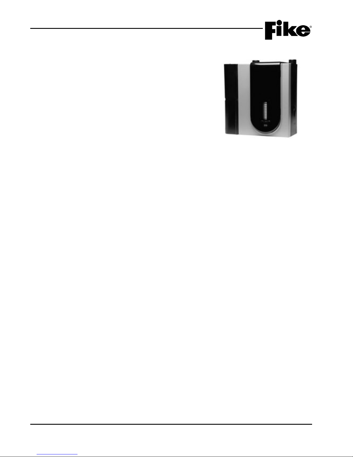
3.0 SYSTEM COMPONENTS
3.6.6 FAAST ASPIRATING SM O KE DETECTORS
STANDARD FAAST UNIT, P/N 68-140
FAAST XT UNIT, P/N 68-302
The FAAST aspirating smoke detectors (See Exhibit 3-30) are
intelligent, air sampling-type smoke detectors that continuously
draws air from the controlled environment through a series of
sampling holes to monitor the environm ent f or smoke particulate.
This enables FAAST to accur ately detect incipient f ire conditions
as early as 30 to 60 m inutes befor e a fire ac tuall y starts for Early
Warning Fire Detection and Very Early Warning Fire Detection.
The detector combines dual source (blue LED and infra-red
laser) optical smoke detection with advanced algorithms to
detect a wide range of fires while maintaining enhanced
immunity to nuisance particulates. FAAST system conditions are
displayed at the user interface and at the Cheetah Xi control
panel. The user interface provides a clear indication of the
system status, particulate levels, alarm levels, air flow and faults.
Features:
Exhibit 3-30: FAAST Detector
• Communicates on the signaling line circuit (SLC)
• Unit P/N 68-140 monitors up to 8,000 ft
• Unit P/N 68-302 monitors up to 20,000 ft
2
(743 m2) with single sampling pipe
2
(1858 m2) with up to four sampling pipes
• Wide sensitivity range of 0.00046% to 6.25% obs/ft. (0.0015% to 20.0%/m)
• Five configurable set points, programmable for latching or non-latching
• Two sensitivity modes (Acclimate and Day/Night/Weekend)
• Six sets of relay contacts
• Selectable fan speed
• Email notification
• 18000 event log
• Remote monitoring via Ethernet/IP
• USB connectivity for network configuration or data retrieval
Refer to the product documentation supplied with the FAAST detector for installation, operation and
maintenance instructions.
3-16 Cheetah Xi 50 Installation Manual UL S2203
Rev 6, 09/2015 P/N: 06-369 FM
Page 35
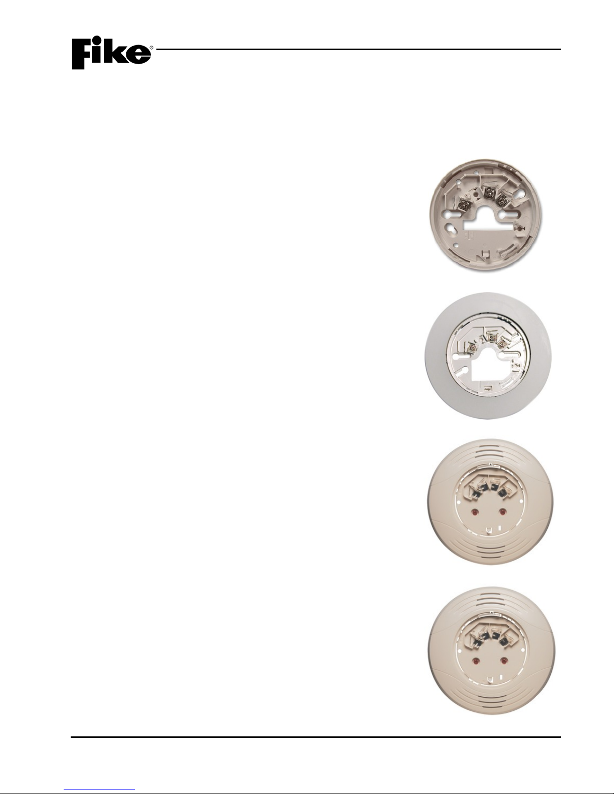
3.0 SYSTEM COMPONENTS
Exhibit 3-32: 6-inch Base
Exhibit 3-33: Sounder Base
3.7 DETECTOR BASES
Several detector bases are availabl e to all ow conn ection of the addr essable detectors to the panel’s signalin g
line circuit (SLC). E ach base pro vides a twist-loc k feature for sec uring the detector to the base. Each base
also provides a connection point for an optional Remote LED (P/N 02-3868), as described in Section 3.8.
A brief description of each detector base and its features is provided in this section for reference purposes.
3.7.1 FOUR-INCH BASE, P/N 63-1055 (System Sensor EB)
BASE W/ ISOLATOR, P/N 63-1061 (System Sensor EBI)
The Four-Inch Base (S ee Exhibit 3-31) can be used with any of the
Cheetah Xi 50 detectors. It mounts directly to 3 1/2 inch octagon
boxes and 4 inch square boxes with plaster ring, and European
boxes with 50, 60, and 70 mm screw spacing. The isolator version
provides complete short circuit isolation for NFPA Class X wiring
when used with an isolator detector.
3.7.2 SIX-INCH BASE, P/N 63-1054 (System Sensor EBF)
BASE WITH ISOLATOR, P/N 63-1060 (System Sensor EBFI)
Exhibit 3-31: 4-inch Base
The Six-Inch Base (See Exhibit 3-32) can be used with any of the
Cheetah Xi 50 detectors. It m ounts directly to 3-1/ 2 inch and 4 inc h
octagon boxes (with or with out plas ter rin gs), and s ingle gan g boxes .
The isolator version provides complete short circuit isolation for
NFPA Class X wiring when used with an isolator detector.
3.7.3 SOUNDER BASE, P/N 63-1064 (System Sensor EBS)
The sounder base (See Exhibit 3-33) provides the ability to notify
occupants near the de tection device(s). The base includes a loca l
85 db sounder that can be activated upon the specific detector
alarm. It is designed t o follow the rem ote LED programm ing for the
detector attac hed to the base and can be configured for 8 different
sounds and/or priorities. This base requires separate 24VDC
continuous auxiliary power from the main control panel.
3.7.4 RELAY BASE, 6”, P/N 63-1063 (System Sensor EBR)
The relay base (See Exh ibit 3-34) provides a local dry co ntact relay
(Form C) output that can be activated for any or multiple states or
zone activation. If def ault programming is used, the r elay will follow
the remote LED progr amm ing for the detector. This base does NO T
require separate 24VDC aux iliar y power fr om the main c ontrol pane l.
It obtains its necessary power from the SLC.
UL S2203 Cheetah Xi 50 Installation Manual 3-17
FM P/N: 06-369 Rev 6, 09/2015
Exhibit 3-34: Relay Base
Page 36
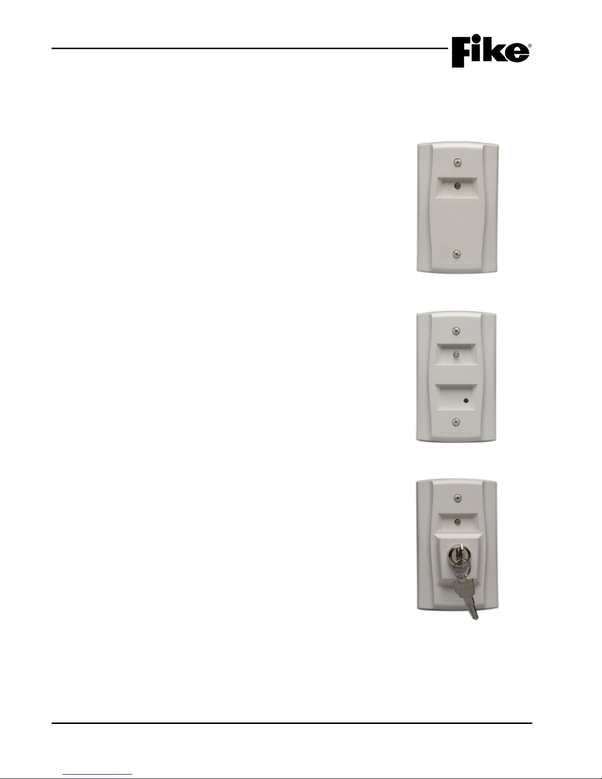
3.0 SYSTEM COMPONENTS
3.8 REMOTE TESTING AND NOTIFICATION ACCESSORIES
The following accessories add functionality to the Cheetah Xi 50 detection system by allowing quick,
convenient inspections at eye level and effective audible and visual notification options.
3.8.1 REMOTE ANNUNCIATOR, P/N 02-3868
(System Sensor RA100Z)
The remote annunciator (See Exhibit 3-35) can be used with any of
the Cheetah Xi detector bases, including t he duct detector housing.
It is fully programm able f rom the detec tor he ad a nd c a n light different
flashes for diff erent devic es/s tates with up t o 8 dif fer ent prior it y rows.
It mounts directl y to single gang electr ical box with a minimum depth
of 2.5 inches or d irectly to a wall or ceiling. The annunciator’s red
LED can provide visual indication of an alarm condition.
3.8.2 REMOTE TEST STATION, P/N 02-3869
(System Sensor RTS151)
Exhibit 3-35: Remote Annunciator
The remote test station (See Exhibit 3-36) is designed to enable
testing of remotel y m ounted d uct sm ok e detector s fr om a convenie nt
location. It mounts directly to single gang electrical box with a
minimum depth of 2.5 inches or directly to a wall or ceiling. The
annunciator is equipped with a red LED that provides visual
indication of an alarm condition and a magnetic test function that
allows remote testing of the connected detector.
Special programming is required on the associated DUCT detector
when using this remote test station. See programming manual.
3.8.3 REMOTE TEST STATION WITH KEY, P/N 02-4998
(System Sensor RTS151KEY)
The remote test station with key (See Exhibit 3-37) is designed to
enable testing of remotely mounted duct smoke detectors from a
convenient location. It m ounts directly to single gang electrical box
with a minimum depth of 2.5 inches or directly to a wall or ceiling.
The annunciator is equipped with a red LED that provides visual
indication of an alarm condition and a keyed test/r eset function that
allows remote testing and resetting of the connected detector.
Special programming is required on the associated DUCT detector
when using this remote test station. See programming manual.
Exhibit 3-36: Remote Test Station
Exhibit 3-37: Remote Test
Station with Key
3-18 Cheetah Xi 50 Installation Manual UL S2203
Rev 6, 09/2015 P/N: 06-369 FM
Page 37
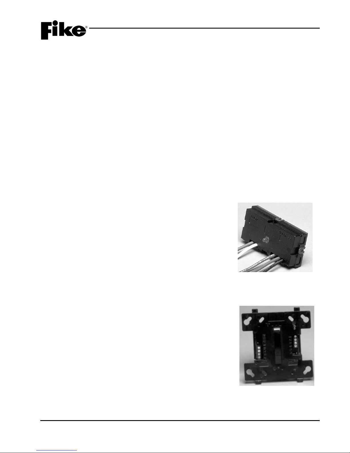
3.0 SYSTEM COMPONENTS
3.9 ADDRESSABLE MODULES
The Cheetah Xi 50 system uses intelligent input and output modules to provide an interface between the
control panel and conven tional notific ation and initiat ing devices. T he operating parameters for each module
are downloaded to the de vice during system configuration into no nvolatile memory. When an input device
(detector or inp ut module) determines that action should be tak en, it transmits a message over the panel’s
SLC loop. Output devices receive this message and us e their downloaded parameter s to determine if they
should take action. Each module is provided with a tricolor LED to ind icate instant device status (green =
normal; yellow=trouble; red = active).
The modules are connecte d to and receive the ir operating power (15-30VDC ) from the host contr ol panel via
the panel’s signaling line circuit (SLC) . The SLC loop is capab le of supporti ng up to 50 addressable device s
in any combination of dete ctors and modules. Each addressable device is assi gned a unique SLC address
that allows it to be identified not only by the system controller for device supervision, but by other SLC devices
as well to facilitate peer to peer system operation. A brief description of each addres sable module and its
features is provided in this section for reference purposes.
Refer to Fike docum ent 06-369-2, “Cheetah Xi 50 Operations Manual” for details of module op eration and
available programming features.
Refer to installation and maintenance instructions supplied with each module for more information.
Note: Module electronic s are rated 32° - 120°F ( 0° - 49°C), 10- 93% relative humidity, unless other wise
noted.
3.9.1 MINI MONITOR MODULE, P/N 55-045
MINI MONITOR MODULE WITH ISOLATOR, P/N 55-050
The Mini Monitor Module ( See Exhibit 3-38) can be used to monitor
normally open or normally c losed contacts of con ventional initiating
devices. It is designed for m ounting in a small junction box directly
behind the monitored device. This module will monitor a Class B
wired input device only using the 39K ohm end of line resistor . The
isolator version provides complete short circuit isolation for NFPA
Class X wiring.
3.9.2 MONITOR MODULE, P/N 55-041
MONITOR MODULE WITH ISOLATOR, P/N 55-046
The Monitor Module ( See Exhibit 3-39) is used to monitor normally
open or normally closed contacts of conventional initiating devices
wired either Class B or Class A. Class B wiring requires the us e of a
39K ohm end of line resistor . The isolator version prov ides com plete
short circuit isolat ion f or NFPA Class X wiring. A module cover pl ate
(not shown) is included with the module.
Exhibit 3-38: Mini Monitor Module
UL S2203 Cheetah Xi 50 Installation Manual 3-19
FM P/N: 06-369 Rev 6, 09/2015
Exhibit 3-39: Monitor Module
Page 38
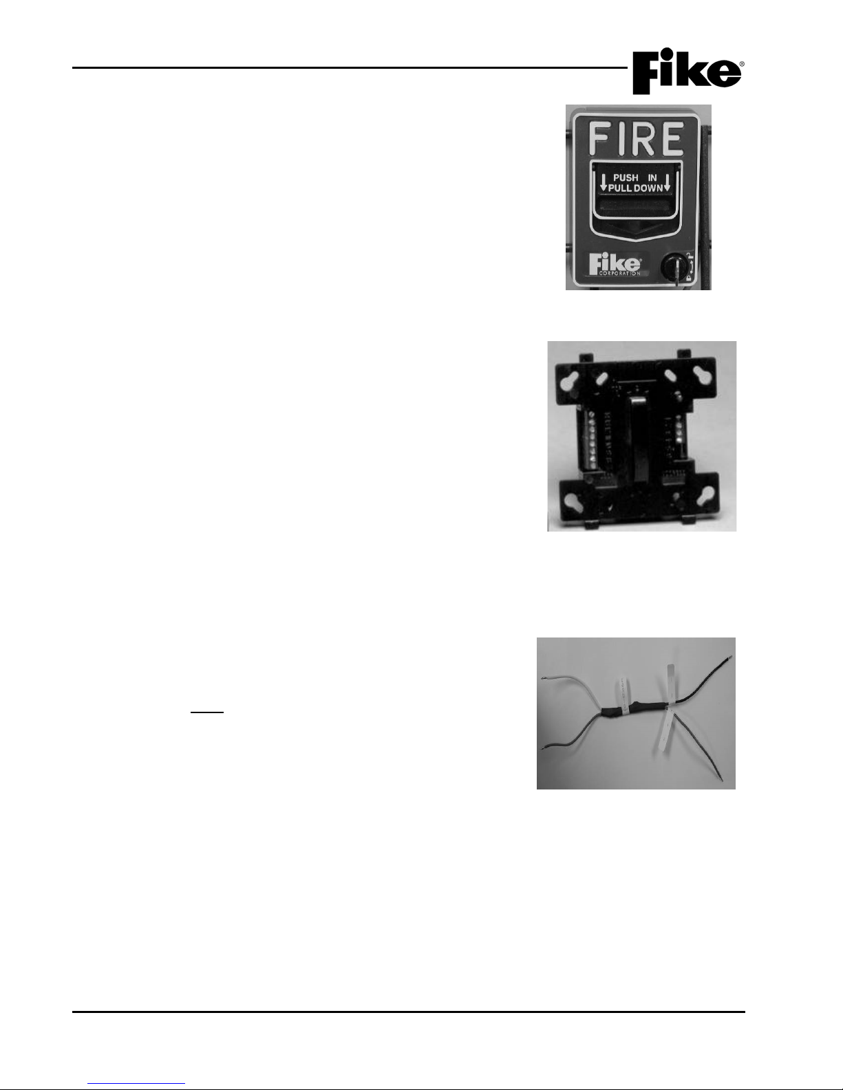
3.0 SYSTEM COMPONENTS
3.9.3 ADDRESSABLE PULL STATION, P/N 20-1063
ADDRESSABLE PULL STATION WITH ISOLATOR,
P/N 20-1064
The Addressable Pull Station (See Exhibit 3-40) is a non-coded,
dual-action manual pull station. A Mini Monitor Module is housed
inside the pull station to provide an alarm initiating input to the
control panel. The isolator version provides complete short circuit
isolation for NFPA Class X wiring.
3.9.4 SUPERVISED CONTROL MODULE, P/N 55-042
SUPERVISED CONTROL MODULE WITH ISOLATOR,
P/N 55-047
The Supervised Con trol Module (See Ex hibit 3-41) is used to switch
an external power supply or audio amplifier to notification appliances.
The module monitors the external po wer input for los s of power and
signals the Cheetah Xi 50 panel accord ingl y. The m odule inc ludes a
tri-color LED for instant indication of device status. The module is
capable of providing an optional pulsing output to signal different
states, when interfaced with the Cheetah Xi 50 addressable loop.
The isolator version provides complete short circuit isolation for
NFPA Class X wiring. A module cover plate (not sho wn) is inclu ded
with the module.
In addition to interfacing with notification appliances, the SCM can
also be used to operate either of the following interfaces:
Exhibit 3-40: Pull Station
Exhibit 3-41: Supervised
Control Module
3.9.4.1 SOLENOID PROTECTION ASSEMBLY, P/N 10-2360
The SCM can be connected to a singl e sprink ler s olenoid r ated u p to
2 amps maximum at 24VDC. The Solenoid Protection Assembly
(See Exhibit 3-42) must be used when connec ting a solenoid to th e
SCM. Refer to Fike document 06-186 for compatible sprinkler
solenoids (Factory Mutual Approved Groups A-G).
Refer to Fike document 06-344 for more information.
Exhibit 3-42: Solenoid
Protection Assembly
3-20 Cheetah Xi 50 Installation Manual UL S2203
Rev 6, 09/2015 P/N: 06-369 FM
Page 39

3.0 SYSTEM COMPONENTS
3.9.4.2 MASTERBOX INTERFACE, P/N 10-2413
The Masterbox Interf ace (See Exhibit 3-43) provides the Cheetah Xi
50 control panel with the ability to activate a Local Energy Type
Auxiliary Fire Alarm S ystem as defined by NF PA 72. The Masterbox
Interface must be used in conjunction with a Supervised Control
Module (P/N 55-042/55-047).
Refer to Fike document 06-229 for more information.
3.9.5 RELAY MODULE, P/N 55-043
RELAY MODULE WITH ISOLATOR, P/N 55-048
The Relay Module (See Exhibit 3-44) provides two Form C dry
contact relays configurable for single operation via the intelligent
addressable loop. It contains a wide range of operating modes
including multi-zone operation of up to 4 different states and multistate programming. Optional feedback or independent contact
closure input available for use on non-critical input such as
monitoring the relay closure or closure from the device that it is
monitoring. The isolator version provides complete short circuit
isolation f or NF PA Class X wiring. A module cover plate (not shown)
is included with module.
3.9.6 RELEASING CONTROL MODULE, P/N 55-052
RELEASING CONTROL MODULE WITH ISOLATOR,
P/N 55-053
The Releasing Control Module (See Exhibit 3-45) provides an
interface between the suppression system solenoid, agent release
module (ARM), or impulse releasing module (IRM) and the
addressable loop. The module requires 24VDC continuous output
power from the panel to power the selecte d rele asing dev ice(s) . The
module provides two different output connections (solenoid or
release module) of which ONLY ONE can be used per module.
Exhibit 3-43: Masterbox Interface
Exhibit 3-44: Relay Module
It contains a wide range of operating modes including multi-zone
operation of up to 4 different states and multi-state programming.
The isolator version provides complete short circuit isolation for
NFPA Class X wiring. A module cover plate (not sho wn) is included
with module.
Exhibit 3-45: Releasing Control
Refer to Fike document 06-106, “Agent Release Module (ARM)
Module
Manual” and 06-552, “Impulse Release Module (IRM) Manual” for
proper connections to ARM(s) or IRM(s).
Note: ARM’s and IRMs may be intermixed on the same releasing
circuit.
3.9.6.1 SOL ENOID PROTECT ION ASSEMBLY, P/N 10-2360
The RCM can be connecte d to a single releasing sol enoid rated up
to 2 amps maxim um at 24VDC. The Soleno id Protection Assem bly
(See Exhibit 3-46) must be used when connecting a solenoid to th e
RCM. Refer to Fike document 06-186 for compatible releasing
solenoids.
Refer to Fike document 06-344 for more information.
UL S2203 Cheetah Xi 50 Installation Manual 3-21
FM P/N: 06-369 Rev 6, 09/2015
Exhibit 3-46: Solenoid
Protection Assembly
Page 40
3.0 SYSTEM COMPONENTS
3.10 VESDA HIGH LEVEL INTERFACE, P/N 68-023
The VESDA HLI ( See Exhibit 3-47) is a custom device that
provides an integrated interface between the CyberCat 50
panel and any VESDA det ector(s) connected to the VE SDA
net (40 detectors maximum), allowing bi-directional
communication. Comm unication between the control panel
and the HLI is made via the control panel’s RS232 peripheral
bus. It should be powered via the Cheetah Xi 50 panel’s
24VDC continuous aux il iar y po wer.
Refer to Fike document 06-158 for more information.
Exhibit 3-47: VESDA HLI
3.11 PROGRAMMING AND CONFIGURATION EQUIPMENT
The items discuss ed in this section are not UL listed; however, one or m ore of these items can be used to
facilitate proper configuration of the Cheetah Xi 50 system.
3.11.1 IR REMOTE TOOL, P/N 55-051
The IR Rem ote tool (See Exhibit 3-48) is a hand-held remote control
that is designed to communicate with the panel and other devices
through any selected device on the loop. It can read device
information such as t ype, loop, address and sens itivity. It can also
write device inform ation such as loop, address, branc h and service
date and initiate de vice test. It features a 16-characte r liquid crystal
display and a 17-button keypad.
Features of the IR Remote Tool:
• Operates with 2 AA Batteries
• Communicates bi-directionally with any device
• Easily configure devices by setting the loop and address
• Quickly read sensitivity levels
• Easily test photo and ion detectors in the sub-floor, as well as duct
detectors
• Immediately record the date serviced
• Instantly perform a remote test of any detector or module, if
programmed for Walktest with IR
• Effortlessly complete a walk test as required
• Access and test hard-to-reach detector or module through any
device
Exhibit 3-48: IR Remote Tool
3-22 Cheetah Xi 50 Installation Manual UL S2203
Rev 6, 09/2015 P/N: 06-369 FM
Page 41
3.0 SYSTEM COMPONENTS
3.11.2 HAND HELD PROGRAMMER, P/N 10-2648 (NON-LISTED)
The Hand Held Programmer (See Exhibit 3-49) provides the us er the
ability to address the Cheetah Xi 50 addressable devices. The
Hand Held Programmer contains the same operating code as the
Cheetah Xi 50 and can be used as a training device and/or
troubleshooting tool.
Refer to Fike document 06-390 for more information.
3.11.3 C-LINX SOFT WARE, P/N 06-327
The C-Linx Software provides a computer interface to the Cheetah Xi
50 controller. It pr ov ides t h e des i gner t he t ools t o design a system in
their office and then load t he configuration at the proj ect site. It also
provides the ability to retr ieve, save and print the configuration and
history of events f rom the control panel as well as perform several
diagnostic functions.
Refer to Fike document 06-448 for more information.
3.11.4 INTERFACE CABLE, P/N 10-2629
Exhibit 3-49: Hand Held
Programmer
The 10-2629 interface cable (See Exhibit 3-50) consists of a USB 2.0
A/B Male-to-Mal e assembly. It should be used whe n programming
using the C-Linx Software to the 50 point panel or Handheld
Programmer.
Note: Requires drivers for proper operation. Drivers can be
downloaded from Fike Customer Portal.
Exhibit 3-50:
UL S2203 Cheetah Xi 50 Installation Manual 3-23
FM P/N: 06-369 Rev 6, 09/2015
Page 42
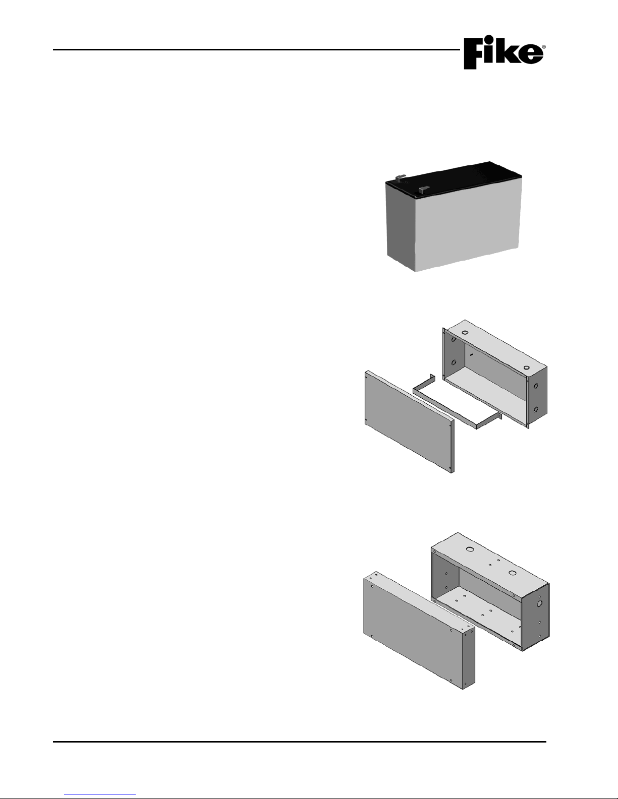
3.0 SYSTEM COMPONENTS
Exhibit 3-52: 33AH Battery Enclosure
3.12 BATTERIES AND BATTERY ENCLOSURES
Batteries are require d for a larm systems f or maintainin g emer gency back -up po wer. Two each 12V batteries
are required and are to be wired in s eries f or maintaini ng a 24VDC bac k -up. Most s ystems require at least a
24 hour standby current with 5 minutes alarm current for determining minimum battery size. Refer to
Appendix A for Battery Calculation form for determining required battery size for system.
3.12.1 BATTERY ASSEMBLIES
P/N 10-2626 – Two 12 AH batteries with wire harness
P/N 10-2190-2 – Two 18 AH batteries with wire harness
P/N 10-2192 – Wire harness for 7.2 AH and 18 AH batteries
P/N 10-2517 - Wire harness with Battery EOL (for use if
batteries give fault but load test good)
3.12.2 BATTERIES
Two 12 volt batter ies w ired in series are re quir ed to m aint ain
24 Vdc backup.
P/N 02-2018 7 AH Battery
P/N 02-4622 12 AH Battery
P/N 02-2820 18 AH Battery
P/N 02-3468 33 AH Battery
P/N A02-0252 40 AH Battery
P/N 02-4206 75 AH Battery
Exhibit 3-51: Sealed Batteries
3.12.3 BATTERY ENCLOSURES
Batteries larger than 18 AH will no t fit inside the Cheetah Xi
50 panel enclosure(s); therefore, one of the follo wing batter y
enclosures must be installed to house the batteries.
Interconnecting cables from the battery cabinet to the
Cheetah Xi 50 enclosure shall be in installed in conduit.
3.12.3.1 33AH BATTERY ENCLOSURE
(BATTERIES NOT INCLUDED)
P/N 10-2154-c (c = Red or Black)
The 33AH Battery Enclosure (See Exhibit 3-52) is a heavy
gauge metal enclosure designed to house two 33AH
batteries. Conduit knockouts are provided to provide entry
of battery wiring. The b ox lid is installed onto the back -box
using the 4 mounting screws provided.
Refer to Fike document 06-534 for more information.
3.12.3.2 75AH BATTERY ENCLOSURE
(BATTERIES NOT INCLUDED)
P/N 10-2236-c (c = Red or Black)
The 75AH Enclosure (See Exhibit 3-53) is a heavy gauge
metal enclosure designed to house two 75AH batteries.
Conduit knockouts are provided to provide entry of battery
wiring. The box li d is ins tal led ont o the back -box using th e 4
mounting screws provided.
Refer to Fike document 06-535 for more information.
Exhibit 3-53: 75AH Battery Enclosure
3-24 Cheetah Xi 50 Installation Manual UL S2203
Rev 6, 09/2015 P/N: 06-369 FM
Page 43

4.0 INSTALLATION
4.1 SYSTEM INSTALLATION SEQUENCE
This section provides general instructions that should be adhered to when installing the Cheetah Xi 50
system. Refer to the installation instruction sheets supplied with each component for specific installation
instructions.
The following checklist is provided to assist the i nstaller during system installation:
Task Refer to
Select the enclosure mounting location. Section 4.2
Select the enclosure mounting option (flush o r surface). Section 4.3
Mount the enclosure. Section 4.4
Wire Selection Section 4.5
Circuit Class Designations Section 4.6
Pull field wiring into enclosure. Section 4.7
Verify the field wiring. Section 4.8
Install internal panel components. Section 4.9
Connect AC power to the controller. Section 4.10
Install batteries. Section 4.11
Apply power to the panel. Section 4.12
Connect field wiring. Section 4.13
Initial power-up with field wiring connected. Section 4.14
Configure the system. Section 4.15
Conduct acceptance testing. Section 4.16
Install the dead-front panel. Section 4.17
4.2 SELECT THE ENCLOSURE MOUNTING LOCATION
The mounting location for the Cheetah Xi 50 enclosure is very important. Fike recommends that all system
enclosures be installed in an area that is readily accessible with sufficient room to allow easy installation and
maintenance, and that is capable of maintaining a nominal room temperature of 0°-49°C / 32°-120°F, with a
relative humidity of 93 percent. Do NOT install in an environment that exceeds these temperature and
humidity ranges.
Additional items to consider when selecting the appropriate mounting location for the enclosure includes:
vibration, dust, moisture, electromagnetic interference, and radio frequency interference. These are all types
of problems that could adversely effect the successful operation and useful life of the electronic components
and should be avoided if possible.
Mount the enclosure at a height that allows easy access to system electronic components for maintenance
and service. Allow sufficient clearance arou nd the enclosure for the outer door to swing free l y.
UL S2203 Cheetah Xi 50 Installation Manual 4-1
FM P/N: 06-369 Rev 6, 09/2015
Page 44

4.0 INSTALLATION
4.3 SELECT THE ENCLOSURE MOUNTING OPTION
The Cheetah Xi 50 system enclosure is designed to be surface or flush mounted. For surface mounting, you
will utilize the mounting holes provided in the back of the enclosure to secure it to the wall. For flush
mounting, you will need to cut an opening in the wall to fit the back-box dimensions (See Exhibit 4-1) and
secure the enclosure in place by utilizing the through holes located on the sides of the box. The enclosure
back-box is designed to fit between wall framing m embers for flush mounting.
Note: The Cheetah Xi 50 enclosure is NOT fire rated; do not install on or in fire rated walls unless steps
are taken to maintain the fire rating of the wall.
4.4 MOUNT THE ENCLOSURE
The following general steps shall be used to install t he sy st em enclosure:
1. The outer door can be removed to make installation of the back-box easier. To remove the outer
door, unscrew the hinge screws located at the top and bottom of the enclosure.
2. Determine the quantity and size of conduit to be attached to the enclosure and punch out the
appropriate conduit knockouts. All field wiring is to be routed into the enclosure via knock-out
openings. Conduit knock-outs are provided for two distinct conduit sizes. Removing just the inside
hole creates a one-half inch (1/2”) opening. Removing the entire opening provides a three-quarter
inch (3/4”) opening.
Note: Unless otherwise detailed in this manual or in other documents relating to this control
panel, the technician shall utilize published standards and references such as NFPA 70 National
Electrical Code, NFPA 72 National Fire Alarm Code, and others, which may be relevant to the
Local Authority Having Jurisdiction for selecti ng the appropriate conductor size and quantity.
Note: If batteries are to be installed in the enclosure, do not use the conduit knock-outs in the
bottom of the enclosure.
3. For surface mounting, mark and pre-drill holes in mounting surface and secure the back-box to the
wall using appropriate mounting hardware.
4. For flush mounting, mark and cut an opening in the wall to fit the back-box dimensions (See Exhibit 4-
1). Wall must be framed to accommodate the back box dimensions. Secure the enclosure in place
with appropriate mounting hardware utilizing the through holes located on the sides of the box.
5. Reinstall the outer door using ex ist i ng mounting hardware.
6. Connect the grounding wire from the outer door to the enclosure back-box. Check for continuity
between door and back-box.
Note: Refer to Fike document 06-624, “50 Point E nclosure Installation Instructions” for further detai l s.
4-2 Cheetah Xi 50 Installation Manual UL S2203
Rev 6, 09/2015 P/N: 06-369 FM
Page 45
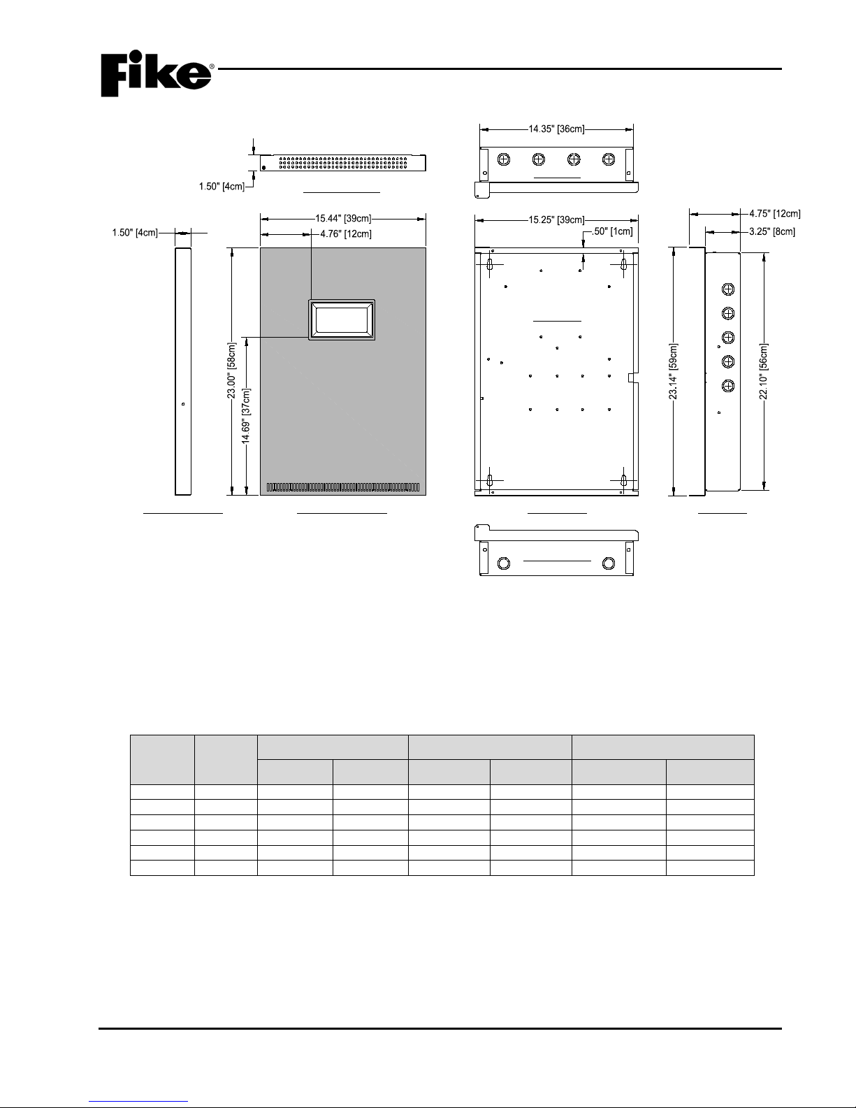
4.0 INSTALLATION
TOP VIEW
FRONT VIEW
BOTTOM VIEW
DOOR FRONT VIEWDOOR SIDE VIEW SIDE VIEW
DOOR TOP VIEW
BACK BOX
(AWG)
18 1 0.040
1.02
7.77
25.5
8.08
26.5
18 7 0.046
1.16
7.95
26.1
8.45
27.7
16 1 0.051
1.29
4.89
16.0
5.08
16.7
16 7 0.058
1.46
4.99
16.4
5.29
17.3
14 1 0.064
1.63
3.07
10.1
3.19
10.4
14 7 0.073
1.85
3.14
10.3
3.26
10.7
Exhibit 4-1: Enclosure Dimensions
4.5 WIRE SELECTION
When planning the type of wire to be used, refer to National Electrical Code (NFPA 70), wire manufacturers
product specifications and National Fire Alarm and Signaling Code (NFPA 72). The wiring specifications
shown in Exhibit 4-2 may be used to estimate the appropriate wire size. Completely review the System
Components section for planning the approp riat e wiri ng for ea ch circuit and device.
Size
Strands
Diameter Uncoated Copper Coated Copper
in. mm ohm/kFT ohm/km ohm/kFT ohm/km
Exhibit 4-2: Conductor Properties (excerpted from NFPA 70, Chapter 9, Table 8)
UL S2203 Cheetah Xi 50 Installation Manual 4-3
FM P/N: 06-369 Rev 6, 09/2015
Page 46

4.0 INSTALLATION
4.6 CIRCUIT CLASS DESIGNATIONS
The circuits on the Cheetah Xi 50 controller and its field devices can be configured for Class B (two wire) or
Class A or X (four wire) operation. Class B wiring does not include a redundant path and the operational
capability stops at a single open. Class A wiring includes a redundant path and the operational capability
continues past a single open. When Class A wiring is utilized, no t-tapping is allowed and the return leg from
the last device on the circuit back to the panel or device must be run in a separate conduit from the main leg.
With Class A wiring, the control panel is constantly supervising all wiring (both main and redundant). Once an
open fault is detected on either leg, the panel immediately transfers communication to the intact redundant leg
of the Class A wiring. Class X wiring is the same as Class A wiring, but requires the use of isolator devices in
order to provide operational capabilities past a single open or short-circuit.
4.7 PULL FIELD WIRING INTO THE ENCLOSURE
The Cheetah Xi 50 system wiring is classified as either power-limited or non-power-limited per NEC article
760. All power-limited wiring must be separated from all non-power-limited wiring by a minimum distance of
1/4 inch (6 mm) within the system enclosure. The Cheetah Xi 50 power-limited versus non-power-limited
circuits are designated a s follows:
Power-Limited circuits include:
P2 – Relays (Alarm, Supervisory, Trouble)
P3 – Computer Interface Connectio n
P4 – VESDA HLI Interface
P5 – Not Used
P6 – RS-485 Peripheral Buss, DACT, AUX Power
P7 – Signaling Line Circuit
P8 & P9 – Notification Appliance Circuits ( 1 & 2)
1
Connected to power-limited or nonpower-limited field wiring, but not
both.
2
When the optional DACT module is installed, the incoming phone
lines (power-limited) must be separated from any nonpower-limited
P2 relay connections.
1,2
Nonpower-limited circuits include:
P1 – AC Power Supply Input and Battery Input
P2 – Relays (Alarm, Supervisory, Trouble)
1,2
When installing optional components within the Cheetah Xi 50 enclosure, refer to the installation instructions
supplied with each component for designation of power-limited versus non-power-limited circuits. Route all
field wiring through the appropriate conduit knockouts, then to the appropriate circuit terminals. Provide
adequate wire length to allow strain relief .
4.8 VERIFY FIELD WIRING
The integrity of the field wiring shall be tested before installing field devices or landing the field wiring to the
system controller. With the end of each circuit open, the following tests shall be conducted:
1. Verify absence of ground-fault on any field wiring prior to connecting the circuits. Refer to
specifications for acceptable readings.
2. Verify no stray voltages exist on any field wiring prior to device installation.
3. Verify each conductor is free from shorts between all other conductors and chas sis.
4. Measure wire resistance with a short across the circuit at a point furthest from circuit start. This is
typically across EOL for Class B and at the panel for Class A or Class X.
Field devices must not be connected if using a meggar or any
means that applies voltages in excess of device ratings to
prevent damage to the devices.
4-4 Cheetah Xi 50 Installation Manual UL S2203
Rev 6, 09/2015 P/N: 06-369 FM
I Caution
Page 47
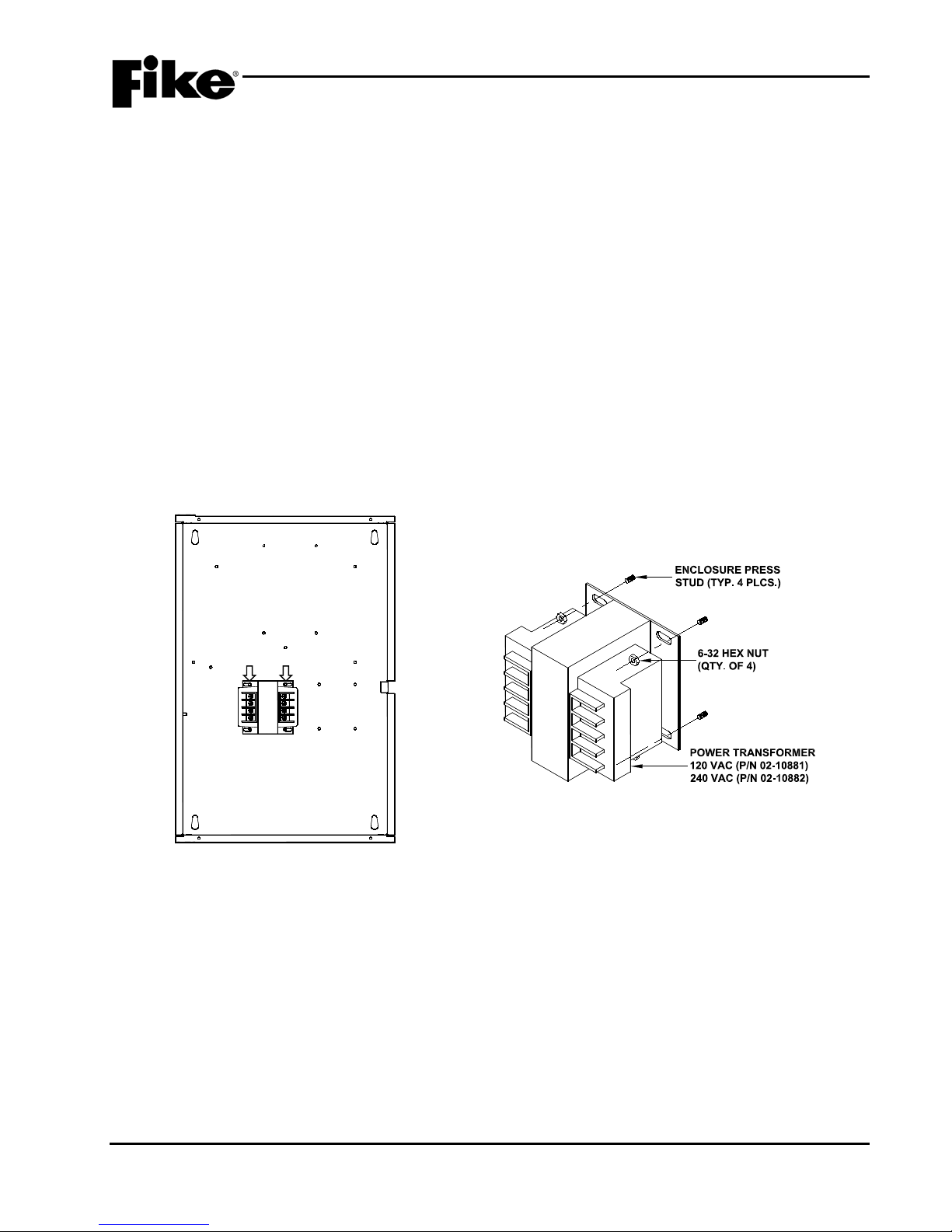
4.0 INSTALLATION
BACK-BOX
TRANSFORMER
4.9 INSTALL INTERNAL PANEL COMPONENT S
Before installing the internal panel components into the enclosure back-box, thoroughly clean the enclosure
making sure that it is clean and free from any construction dust or debris. The Cheetah Xi 50 electronics
contain static sensitive components. Handle the electronics by the edges only and avoid touching the
integrated components. Keep the electronics in the protective static bags it was shipped in until time for
installation. Always ground yourself with a proper wrist strap before handling the module(s) to reduce the risk
of damage due to static discharge.
Note: The mounting hardware for installing the panel components is shipped with the system enclosur e.
4.9.1 INSTALL AC POWER TRANSFORMER
The following general steps shall be used to install the AC power transformer into the back-box:
1. Locate the four threaded press studs provided in the enclosure back-box for mounting the transformer
(See Exhibit 4-3).
2. Position the transformer over the press studs making sure that the transformer’s H1 and H2 (AC
primary input) terminals are facing to the left side of the enclosure. Secure the transfor mer in place
with four 6-32 hex nuts and lock-washers provided with t he enclosure.
Exhibit 4-3: Transformer Mounting Location
UL S2203 Cheetah Xi 50 Installation Manual 4-5
FM P/N: 06-369 Rev 6, 09/2015
Exhibit 4-4: Transformer Mounting
Page 48
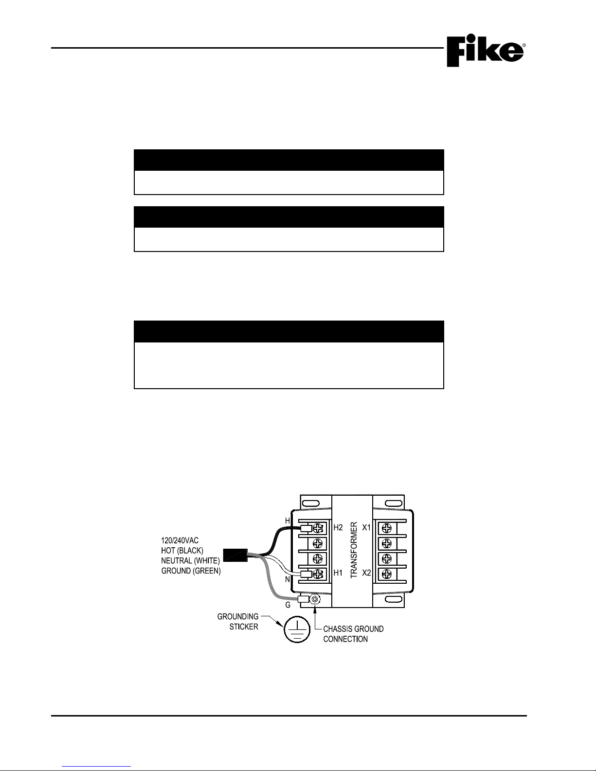
4.0 INSTALLATION
4.9.2 CONNECT AC POWER TO THE TRANSFORMER
System AC line power (120 VAC or 240 VAC, 50/60 Hz) must originate from a dedicated circuit at the main
building power distribution center. The circuit breaker shall be equipped with a lockout mechanism and be
clearly labeled as a "Fire Alarm" circuit. Route the power to the system through the dedicated grounded
metallic conduit.
I Caution
Ensure the power supplied is compatible with the transformer
assembly (120VAC or 240VAC) prior to applyi ng power.
I Caution
Verify that AC power circuit has been turned off before connecting
power wiring to the transformer.
The following general steps shall be used to connect AC power to the transformer:
1. Route the AC hot and neutral wires to the transformer (See Exhibit 4-5).
2. Secure Hot and Neutral wires to terminals H1 and H2.
I Caution
Never swap transformer Primary (H1 and H2) and Secondary (X1
and X2) by connecting AC feed to secondary terminals. Doing so
will cause the transformer to step-up the power resulting in certain
damage to the controller.
3. Install the AC ground wire (G) under the transformer onto the mounting stud identified with the
grounding sticker. This connection provides lightning and transient protection for the panel and must
make a good mechanical connection to the enclo sur e.
4. Tighten the hex nuts to secure the t ransformer and ground wire in place.
5. Align and lower the plastic termi nal cover onto the transformer and snap in place.
6. DO NOT ENERGIZE THE AC POWER SOURCE AT THIS TIME!
Exhibit 4-5: Power Transformer Wiring
4-6 Cheetah Xi 50 Installation Manual UL S2203
Rev 6, 09/2015 P/N: 06-369 FM
Page 49
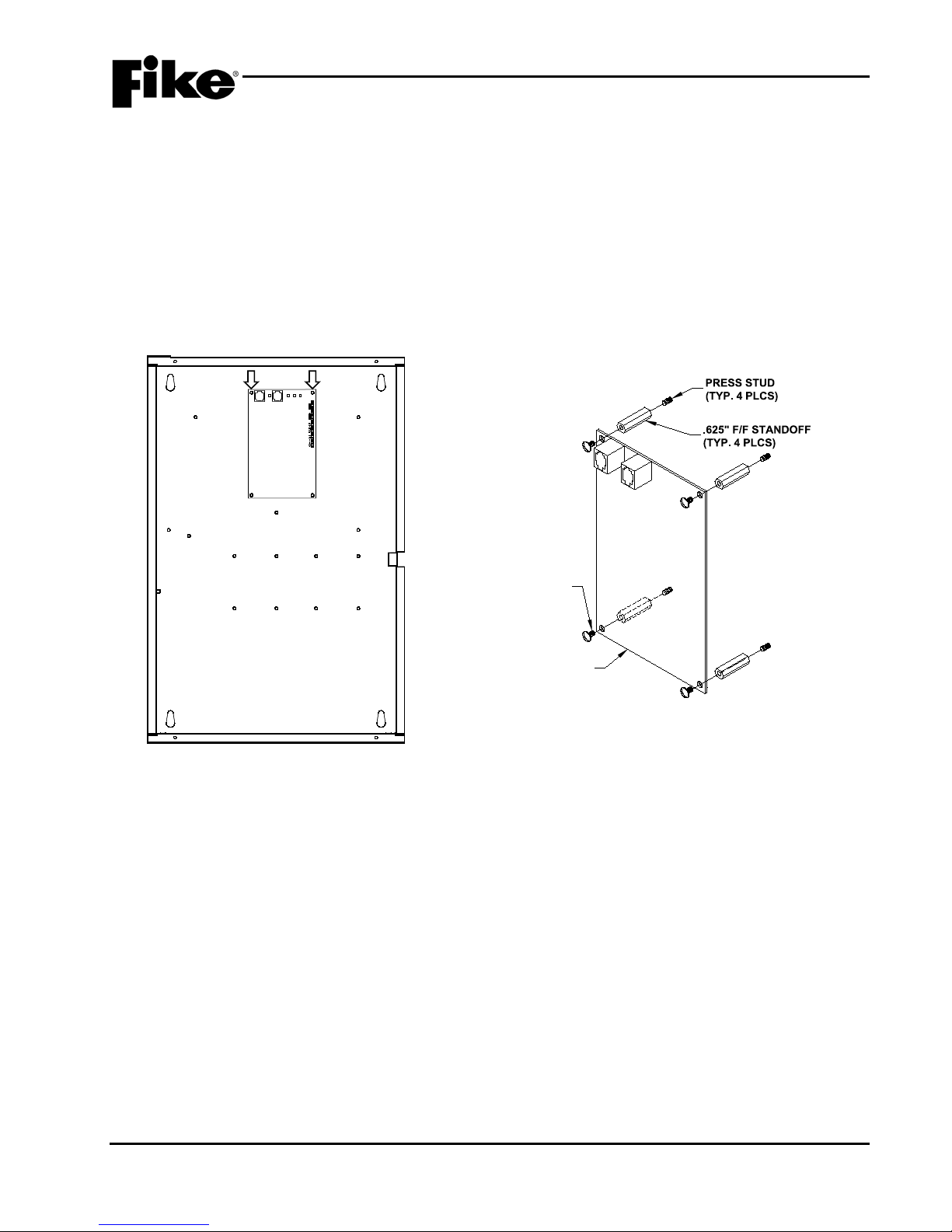
4.0 INSTALLATION
BACK-BOX
DACT
LINE 2
SYS TRBL
HEARTBEAT
LINE 1
Exhibit 4-6: DACT Mounting Location
DACT CARD
6-32 SCREWS
(QTY. 4)
4.9.3 INSTALL OPTIONAL DACT
If the optional DACT (P/N 10-2528) is to be installed within the Cheetah Xi 50 enclosure, it must be installed
prior to installing the control board (See Exhibits 4-6 and 4-7).
The following general steps shall be used to install the DACT i nto the back-box:
1. Locate the four threaded press studs provided in the enclosure back-box for mounting the DACT (See
Exhibit 4-6) and install the four hex stand-offs (.625, F/F #6-32) supplied with the DACT onto the
threaded press studs.
2. Align the mounting holes provided in the four corners of the DACT with the stand-offs and secure in
place using the four #6-32 screws supplied with the DACT (See Exhibit 4-7).
Exhibit 4-7: DACT Mounting
Refer to the installation instructions suppli ed with the DACT for specific installation instructions.
UL S2203 Cheetah Xi 50 Installation Manual 4-7
FM P/N: 06-369 Rev 6, 09/2015
Page 50
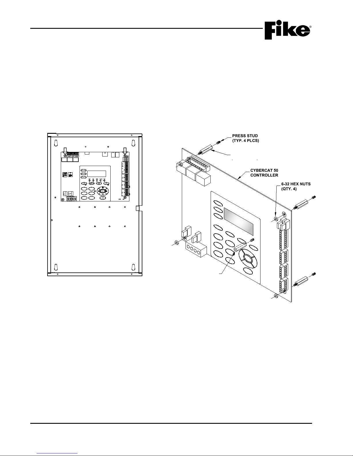
4.0 INSTALLATION
K5 K6
K7
JTAG
P10
24V
P5
P4
AUX#1 F4 4A
P3
P2
10-2620 REV
02-11544 REV A
F1
F2
F3 F6
F5
F4
CYBER CAT 50
FIKE CORPORATION
01:39:37A 06/14/2011
AL:000 SU:000 TR:000
BACK-BOX
CONTROLLER
2" F/F ST ANDO FF
(KEYPAD SUPPORT)
2.5” M/F STANDOFF
(TYP. 4 PLCS)
2.5” F/F STANDOFF
(KEYPAD SUPPORT)
4.9.4 INSTALL THE CHEETAH XI 50 CONTROLLER
The following general steps shall be used to install the Cheetah Xi 50 controller:
1. Locate the four threaded press studs provided in the enclosure back-box for mounting the controller
board (See Exhibit 4-8) and install the four hex stand-offs (2.5”, M/F #6-32) supplied with the
enclosure onto the threaded press studs.
2. Locate the threaded press studs provided in the enclosure back-box for keypad support (See Exhibit
4-9) and install the hex stand-off (2.5”, F/F #6-32) supplied with the enclosure onto the threaded
press stud.
3. Align the mounting holes provided in the four corners of the controller board with the stand-offs and
secure in place using the four #6-32 hex nuts suppl i ed with the enclosure (See Exhibit 4-9).
Exhibit 4-8: Controller Mounting Location
4-8 Cheetah Xi 50 Installation Manual UL S2203
Rev 6, 09/2015 P/N: 06-369 FM
Exhibit 4-9: Controller Mounting
Page 51
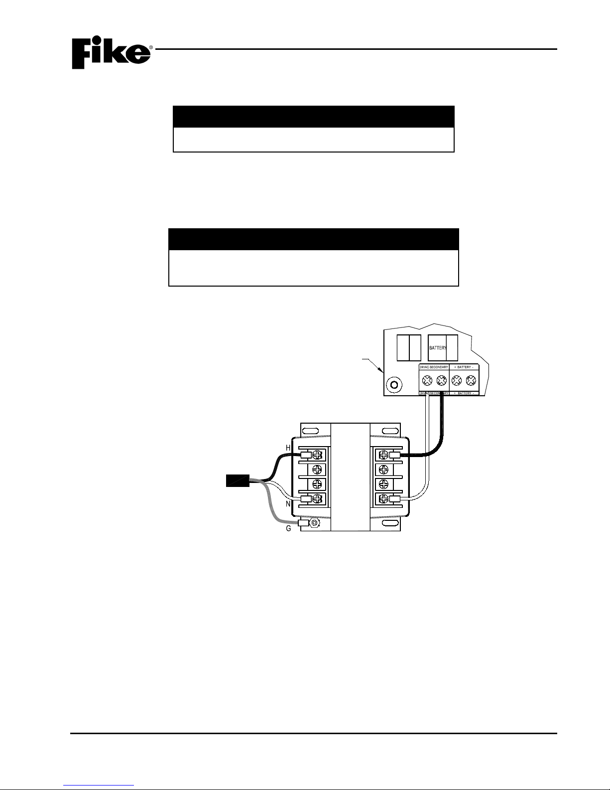
4.0 INSTALLATION
P1
F1
AC
15A
F2
15A
H2
H1X1X2
TRANSFORMER
AC POWER
INPUT
CHEETAH Xi 50
CONTROLLER
Exhibit 4-10: AC Power Connections
4.10 CONNECT AC POWER TO THE CONTROLLER
a WARNING
AC power connections to the Cheetah Xi 50 Controller must
be made with the main power breaker locked o ut.
The following general steps shall be used to connect AC power to the controller:
1. Connect wiring from the secondary side of the AC power transformer (X1 and X2) to the controller’s
P1 - 24VAC Secondary terminals (See Exhibit 4-10) making sure to land wires to the correct
terminals.
I Caution
The transformer input should never be connected to the
battery input. Reversing the AC and Battery input will damage
the controller.
2. Do NOT energize the AC power source at t his time!
UL S2203 Cheetah Xi 50 Installation Manual 4-9
FM P/N: 06-369 Rev 6, 09/2015
Page 52
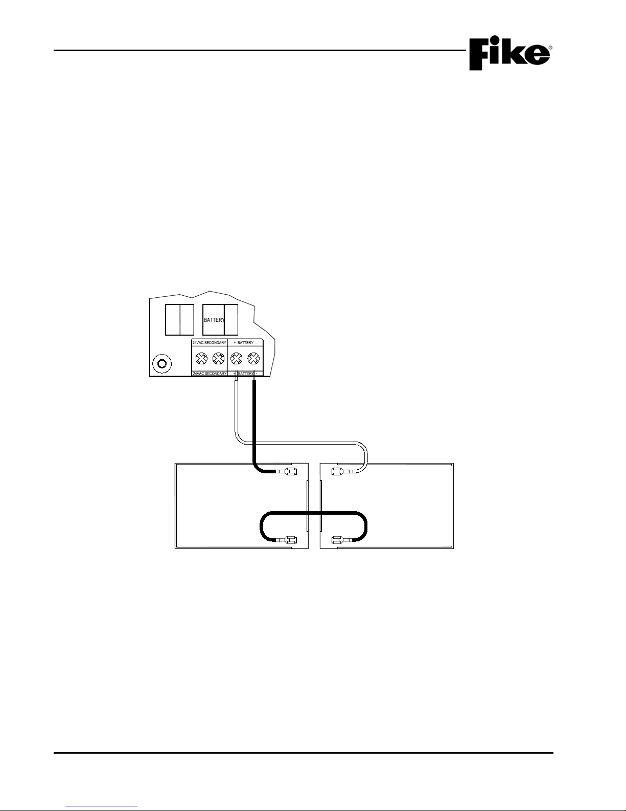
4.0 INSTALLATION
P1
F1
AC
15A
F2
15A
(First)
12 VDC
BATTERY
RED (+)
BLACK (-)
JUMPER
(Second)
12 VDC
BATTERY
(-) (+)
(+) (-)
Exhibit 4-11: Battery Connections
4.11 INSTALL BATTERIES
The Cheetah Xi 50 enclosure is capable of housing up to two (2) 18 AH batteries. Where larger or additional
battery Amp-Hours are required, a separate battery cabinet can be installed to house the batteries. The
battery cabinet must be installed in the same room as the control panel with a maximum wire length of 10 ft.
(3 m). Interconnect wiring shall be 14 AWG minimum and shall be installed in conduit.
The following general steps shall be used to install the batteries:
1. Install the batteries (2) into bottom of the enclosure and/or into the separate battery cabinet.
2. Connect the positive (+) battery cable lead from the (P1) positive battery input terminal to the positive
(+) terminal of the first battery.
3. Connect the negative (-) battery cable lead from the (P1) negative battery input terminal to the
negative (-) terminal of the second battery.
4. A jumper is supplied to provide the connection between the negative (-) terminal on the first battery to
the positive (+) terminal on the second battery . Do NOT install this jumper at this time!
4.11.1 BATTERY CUTOFF
The Cheetah Xi 50 panel has battery cutoff feature that allows the system batteries to be automatically
disconnected from the load if the system’s operating voltage (AC/DC) drops below 19 volts. This feature
prevents the batteries from being discharged beyond their end-of-discharge terminal voltage thus preventing
potential damage to the batteries or control unit, which could result in abnormal operation of the control unit
during battery discharge period or on re-energizing by the main power supply. Upon restoration of the main
power supply, the batteries shall be automatically reconnected to the system. Refer to Appendix D for battery
cutoff wiring diagram.
4-10 Cheetah Xi 50 Installation Manual UL S2203
Rev 6, 09/2015 P/N: 06-369 FM
Page 53

4.0 INSTALLATION
4.12 APPLY POWER TO THE PANEL
Prior to connecting any field wiring to the panel, apply power to the controller and verify proper operation.
The following general steps shall be used to apply power to the controller:
1. Turn on the breaker and power the control panel with AC power only. The AC Power LED on the
control panel display should illuminate. In addition, the system Trouble LED should illuminate
because the batteries are not connected.
2. Install the supplied jumper cable between the negative (-) terminal of the first battery to the positive
(+) terminal of the second battery.
3. With the batteries connected, verify that the only the system AC POWER LED is illuminated.
4. Identify and fix any problems indicated by the controller.
5. Power down the controller by first disconnecting the batteries (DC power), then transferring the AC
circuit breaker.
I Caution
Immediately power down the system (DC followed by AC) if
the display shows improper characters, you smell smoke, or
if you see sparks. Each of these conditions indicates
improper connections or malfunction of components.
UL S2203 Cheetah Xi 50 Installation Manual 4-11
FM P/N: 06-369 Rev 6, 09/2015
Page 54
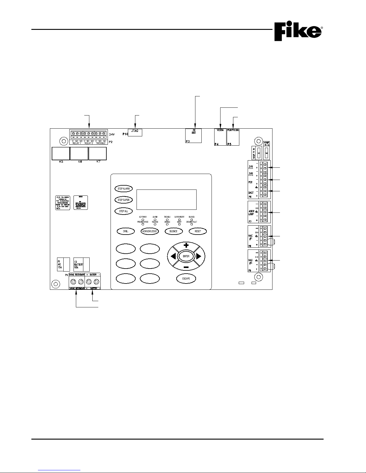
4.0 INSTALLATION
(P6) 24VDC AUXILIARY
POWER #1
(P1) BATTERY CONNECTIONS
(P1) AC POWER CONNECTIONS
(P6) DACT INTERFACE
(P7) SIGNALING LINE
CIRCUIT
(P9) NOTIFICATION
APPLIANCE CIRCUIT #2
(P5) NOT USED
(P4) VESDA HLI INTERFACE
RS232
(P3) PANEL PROGRAMMING
INTERFACE
(P10) FIKE USE
ONLY
(P2) DRY CONTACT RELAYS
10-2620 REV
02-11544 REV A
F1
F2
F3 F6
F5
F4
CHEETAH Xi 50
FIKE CORPORATION
01:39:37A 06/14/2011
AL:000 SU:000 TR:000
(P8) NOTIFICATION
APPLIANCE CIRCUIT #1
(P6) 24VDC AUXILIARY
POWER #2
Exhibit 4-12: Cheetah Xi 50 Board Terminal Connections
4.13 CONNECT FIELD WIRING
The Cheetah Xi 50 Controller is equipped with terminal block connectors, which facilitate easy connection of
field wiring to the appropriate terminals. See Exhibit 4-12 for terminal block designations and their general
function for reference purposes.
4-12 Cheetah Xi 50 Installation Manual UL S2203
Rev 6, 09/2015 P/N: 06-369 FM
Page 55
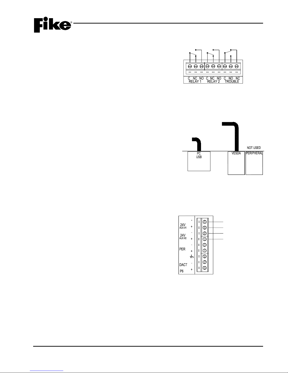
4.0 INSTALLATION
24V
P2
P5
P4
P3
VESDA HLI INTERFACE
CABLE (14 FT. MAX.)
PROGRAMMING
CABLE FROM
LAPTOP PC
Exhibit 4-14: RS232 Wiring (P3-P5)
24VDC @ 1.75
AMPS MAX.
24VDC @ 1.75
AMPS MAX.
4.13.1 GENERAL RELAY WIRING (P2)
The panel provides three Form-C relay contacts which
will activate on system Alarm, Supervisory, and Trouble
conditions (See Exhibit 4-13). The Trouble Relay is
normally energized to allow it to change state when
power to the main control board is lost. Relay contacts
are shown with power applied and no Troubles present.
The circuit board provides labeling for the three form C
relays where C=common; NC=normally closed; and
NO=normally open. These connections can all be wired
power-limited or non-power-limited, but not both.
4.13.2 RS232 WIRING (P3-P5)
The panel provides one USB and one RS232 jack which
allow intelligent devices to link into the Cheetah Xi 50
controller (See Exhibit 4 -14). These connections are all
supervised and power-limited.
P3 – USB jack dedicated for programming the panel
using the C-Linx software. USB programming cable P/N
10-2629 (or equivalent) must be used for this
connection.
Exhibit 4-13: P2 Relay Connections
P4 – RS232 jack dedicated for connection to a VESDA
network via a VESDA HLI interface. A 14 ft. (4.27m)
serial cable P/N 02-3053, is provided with the HLI for
connection to the controller. The HLI is considered a
permanent connection to the RS232 port (P4) and shall
be located within 50 ft. (15.24m) from the contr ol panel.
P5 – currently not used.
4.13.3 AUXILIARY POWER WIRING (P6)
The panel provides two 24VDC, power-limited,
supervised, non-resettable power outputs rated at 1.75
amps maximum (See Exhibit 4-15). These power
outputs can be used to power addressable output
modules, graphic annunciators, 4-wire detectors, some
duct detectors, beam detectors, etc.
Note: The Cheetah Xi 50 Control Panel has a total
power capability of 5.25 amps.
Exhibit 4-15: (P6) Auxiliary Power Wiring
UL S2203 Cheetah Xi 50 Installation Manual 4-13
FM P/N: 06-369 Rev 6, 09/2015
Page 56
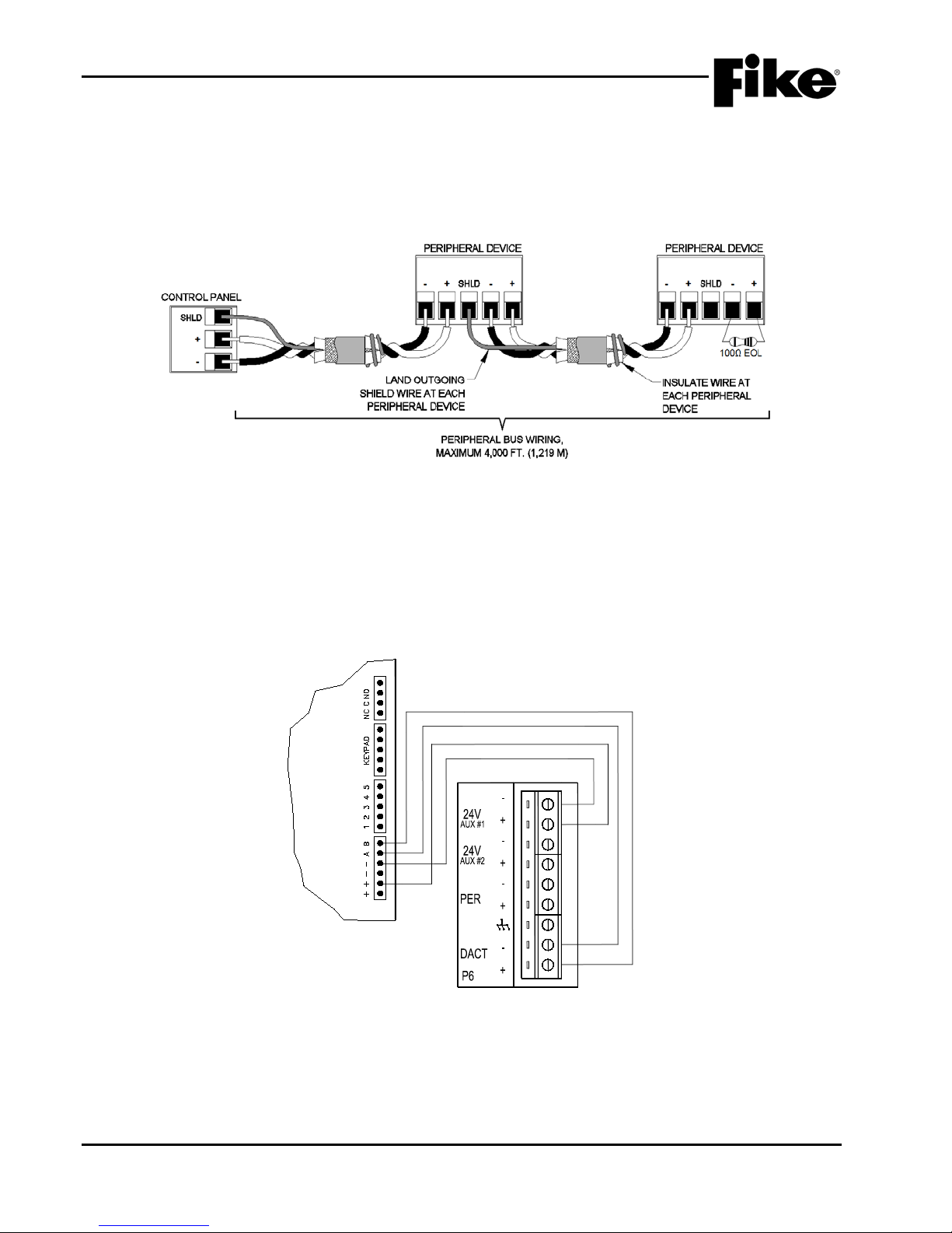
4.0 INSTALLATION
OPTIONAL DACT
B
A
Blue
Yellow
+
-
+
CHEETAH Xi 50
+
-
Red
Black
Exhibit 4-17: (P6) RS485 DACT Wiring
4.13.4 PERIPHERAL BUS WIRING (P6)
The panel provides a single isolated RS485 data interface between the Cheetah Xi 50 panel and compatible
peripheral devices identified in Section 3.5. The peripheral bus must be connected in a daisy chain
configuration as shown in Exhibit 4-16. These connections are all supervised and power-limited. Do not
branch or star tap the peripheral bus.
Exhibit 4-16: (P6) RS485 Peripheral Bus Wiring
4.13.5 DACT WIRING (P6)
The panel provides a dedicated connection point for the optional internal Digital Alarm Communicator
Transmitter (See Exhibit 4-17).
Refer to Fike document 06-479 for more details.
4-14 Cheetah Xi 50 Installation Manual UL S2203
Rev 6, 09/2015 P/N: 06-369 FM
Page 57
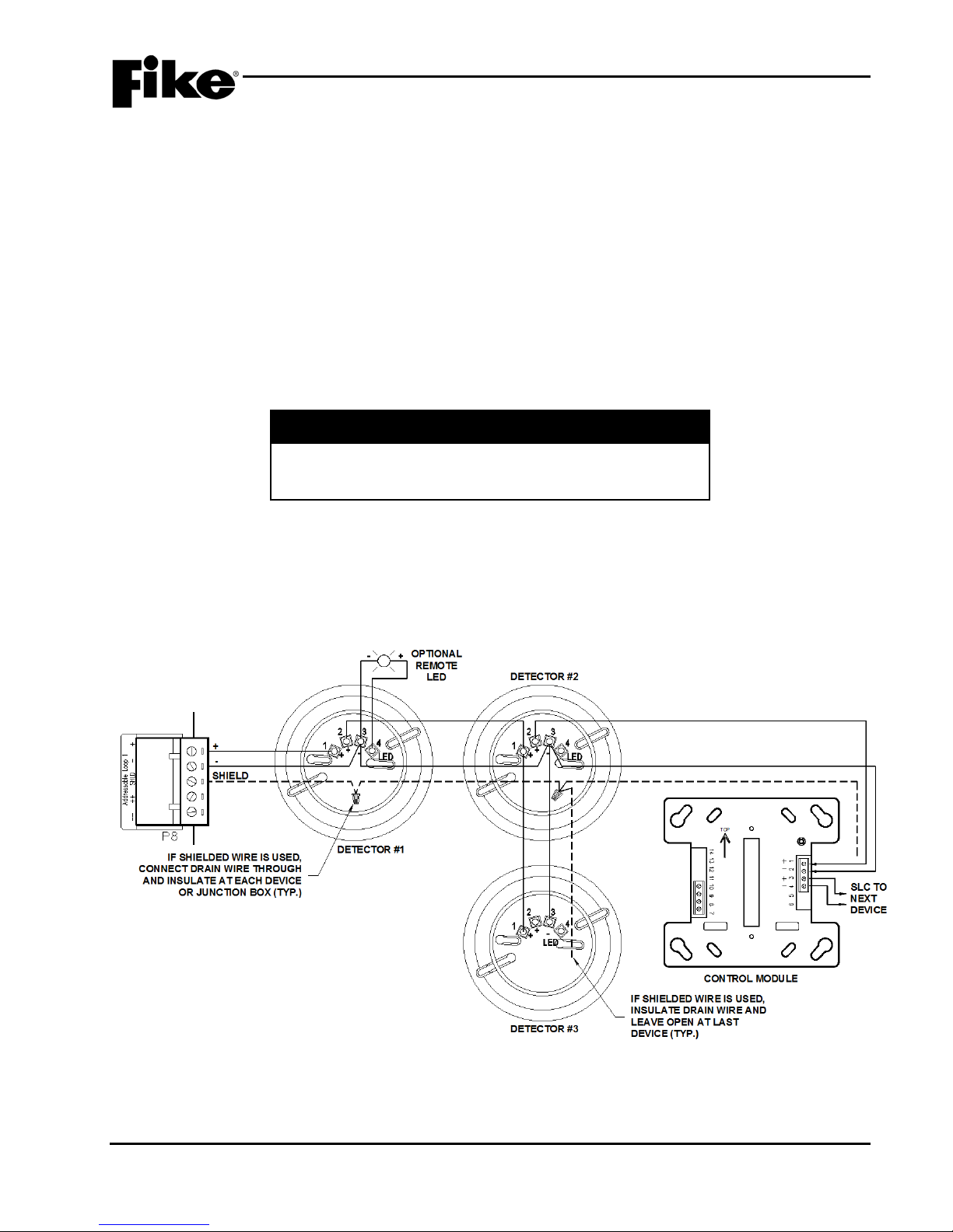
4.0 INSTALLATION
4.13.6 ADDRESSABLE LOOP WIRING (P7)
Communication between the control panel and each intelligent, addressable device takes place through the
Signaling Line Circuit (SLC). The SLC is supervised and power-limited. The SLC loop can be wired to meet
the requirements of NFPA Class B, Class A, o r Class X circuits (See Exhibit 4-18 and 4-19). For details on
how to wire each addressable device to the SLC loop, refer to the installation instructions supplied with each
device.
Be aware of surrounding environment when installing the addressable loop, looking for possible sources of
electrical interference. All SLC wiring should be segregated from such sources for optimum operation.
Conduit and shielded cable help prevent electrical interferences from being induced. Shielded wire is not
required, but if used install the outgoing drain wire at the panel. Connect it through and insulate at each
junction box and leave unconnected and insulated at the last device.
FM Approved Deluge and Pre-action Sprinkler operation requires that initiating device circuits be
Class A and wired to FM Listed/Approved devices.
I Caution
If using a High voltage device to verify ground isolation of
loop wiring, do not expose devices or modules to the high
voltage. Damage to the devices will occur.
4.13.6.1 CLASS B WIRING
Exhibit 4-18 shows the typical wiring of a supervised and power-limited two-wire SLC that meets NFPA 72,
Class B requirements. This wiring method does not include a redundant pach. In the event of a single wire
break, the communication to devices after the break is lost. This wiring method will support t-tapping
(Detector #3 is T-Tapped off Detector #2).
UL S2203 Cheetah Xi 50 Installation Manual 4-15
FM P/N: 06-369 Rev 6, 09/2015
Exhibit 4-18: Class B SLC Wiring
Page 58
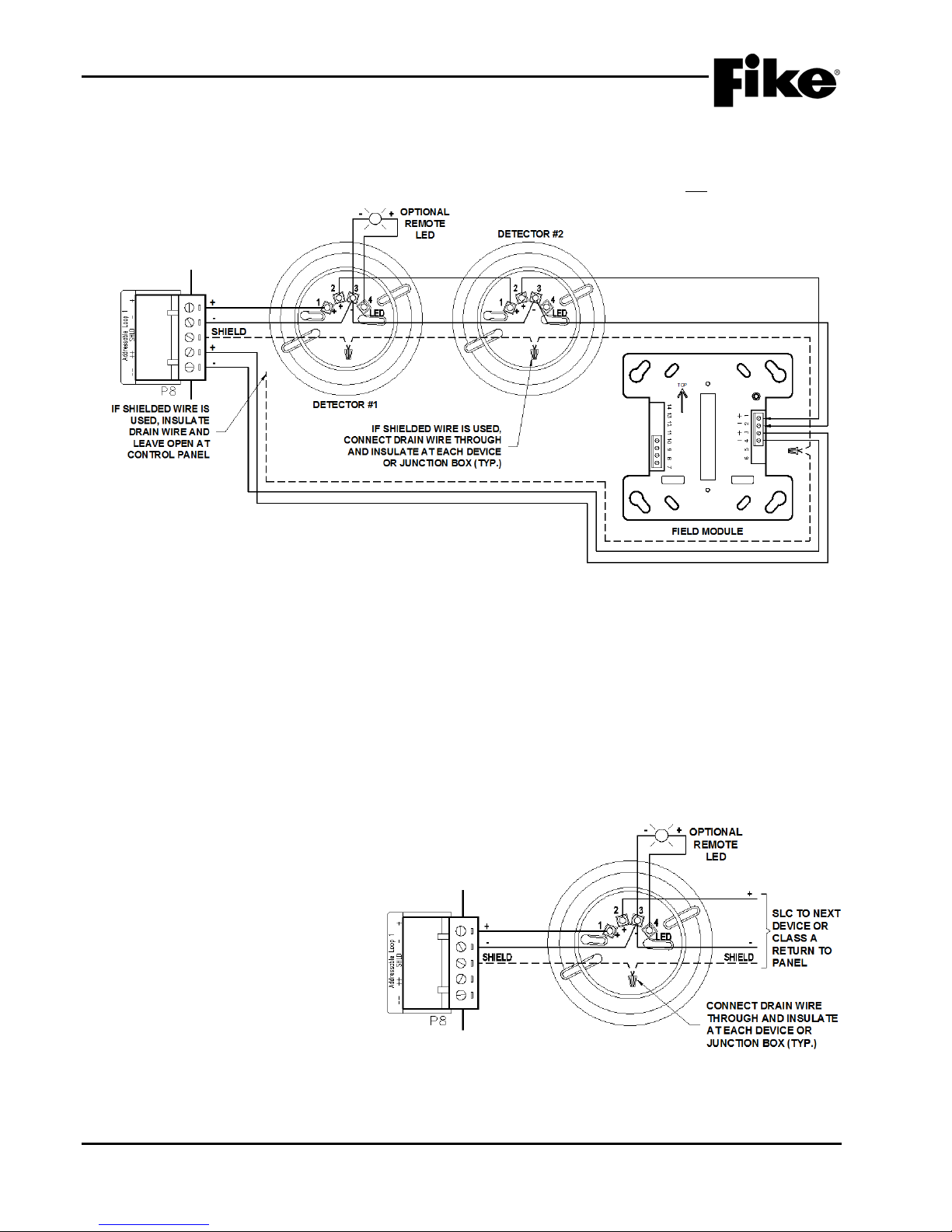
4.0 INSTALLATION
Exhibit 4-19: Class A and Class X SLC Wiring
4.13.6.2 CLASS A OR CLASS X WIRING
Exhibit 4-19 shows typical wiring of a supervised and power-limited four-wire SLC that meets NFPA 72, Class
A or Class X requirements. This wiring method includes a redundant path. In the event of a single wire
break, the communication to devices after the break continues. This wiring method will not support t-tapping
4.13.6.3 CLASS X WIRING
Class X wiring is the same as Class A wiring except that it utilizes isolator devices to provide short-circuit
protection for the signaling line circuit (SLC). The circuitry built-into the isolator devices allow communication
to devices to continue past a single short-circuit. Short circuit protection can be provided for the entire
signaling line circuit or for selected sections of the signaling line circuit. Isolator devices can be installed to
electrically isolate a zone of detectors and/or modules from the remainder of the loop by installing an isolator
type device at the point where the SLC enters and leaves the zone. A maximum of 50 devices can be
installed between two isolator type devices.
Note: If using isolator bases, the loop + is separated between terminal 1 (in) and terminal 2 (out).
4.13.6.4 REMOTE LED WIRING
The detector base has the ability to
attach a remote LED as shown in
Exhibit 4-20. Power for operation of
the LED is drawn from the control
panel’s addressable loop. The
addressable loop is limited to a
maximum of 100 mA total for
addressable devices plus remote LED
devices.
4-16 Cheetah Xi 50 Installation Manual UL S2203
Rev 6, 09/2015 P/N: 06-369 FM
Exhibit 4-20: Remote LED Wiring
Page 59
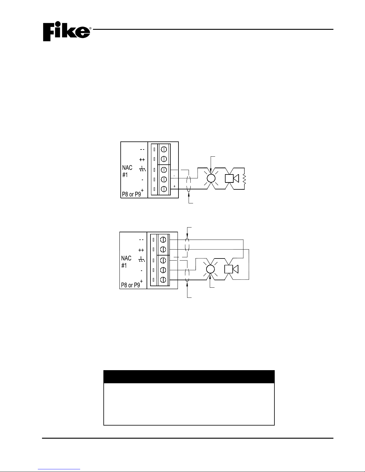
4.0 INSTALLATION
1.2K
EOL
TYPICAL
NOTIFICATION
APPLIANCE
SHIELD WIRE
Exhibit 4-21: (P8/P9) NAC Circuit Wiring – Class B
TYPICAL NOTIFICATION
APPLIANCE
SHIELD WIRE
INSULATE SHIELD WIRE
DO NOT LAND AT PANEL
CLASS A RETURN
Exhibit 4-22: (P8/P9) NAC Circuit Wiring – Class A
4.13.7 NOTIFICATION APPLIANCE CIRCUIT WIRING (P8 & P9 )
P8 and P9 are two separate notification appliance circuits (NAC’s) that provide the ability to activate
compatible, UL-listed notification appliances listed in Fike document 06-186, “Device Compatibility manual”.
The NAC circuits are supervised, power-limited, and can be wired Class B (using 1.2K EOL) or Class A (no
EOL), as shown in Exhibits 4-21 and 4-22. Shielded wiring is not required, however if used, land at the panel
terminal block and pass through at each dev i ce similar to SLC device wiring.
The NACs can be configured to initiate the Gentex Commander Series or System Sensor SpectrAlert Series
sync protocol. This allows all devices (strobes and horns) connected to the circuit to operate in unison. It
also allows the audible devices to be silenced while the visual signals remain operational or silence both
audible and visual devices. This is accomplished without requiring purchase and installation of a separate
sync module. Both circuits must be programmed to use the same manufacturers sync pulse if this option is
used.
4.14 I NITIAL POWER-UP WITH FIELD WIRING CONNECTED
1. Energize AC power to Cheetah Xi 50 controller a nd field power supplies (if installed) with field wiring
connected.
2. Connect batteries to the Cheetah Xi 50 controller and field power supplies (if installed).
3. Validate that all devices begin to function appropriately and wiring is connected properly.
4. Correct all circuit faults.
Immediately power down the system (DC followed by AC) if
the display shows improper characters, you smell smoke, or if
you see sparks. Each of these conditions indicates improper
connections or malfunction of components. After power is
UL S2203 Cheetah Xi 50 Installation Manual 4-17
FM P/N: 06-369 Rev 6, 09/2015
removed, investigate for source of malfunction by checking
module connections in the area of the malfunct i on.
I Caution
Page 60
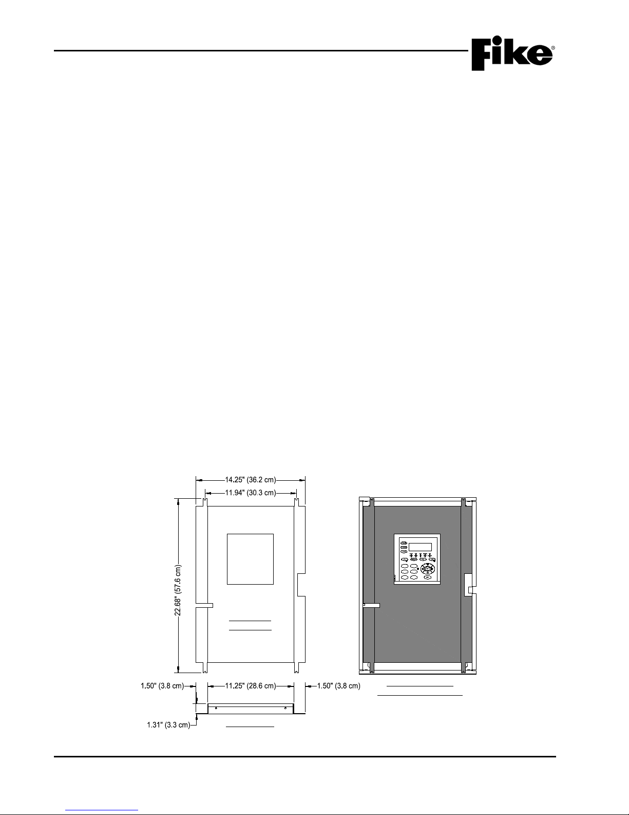
4.0 INSTALLATION
DEADFRONT
BOTTOM VIEW
FRONT VIEW
K5 K6
K7
JTAG
P10
24V
P5
P4
AUX#1 F4 4A
P3
P2
10-2620 REV
02-11544 REV A
F1
F2
F3 F6
F5
F4
P1P2
P3
P4
SW1
ETHERNET MODULE
P/N 10-2627
PANEL FRONT VIEW
WITH DEADFRONT PANEL
Exhibit 4-23: Dead-Front Panel
4.15 CONFIGURE SYSTEM
There are many different methods that can be chosen to configure the Cheetah Xi 50 fire alarm system. The
two most common choices would be to AUTO PROGRAM or ENGINEERED CONFIGURE. Any combination
of these two methods may also successfully accomplish matching the field devices to the installation
configuration requirements. Refer to Fike Document 06-657, “Cheetah Xi 50 Programming Manual” for
specific details on how to configure the system.
4.16 ACCEPTANCE TEST
Once the system has been wired, configured, and any faults corrected, all installed components should be
tested as a system to insure proper operation and to verify compliance with applicable NFPA standards.
Testing should be conducted by a factory-trained fire alarm technician in the presence of a representative of
the Authority Having Jurisdiction (AHJ) and the owner’s representative.
The initial system check is required to verify that all components of the system are installed and operating as
intended. Where test results differ from t hose expected, corrective action must be taken.
Before commencing testing, notify all areas where the alarm sounds and off-premises locations that receive
alarm and trouble transmissions that testing is in progress.
When the system has been tested and found to operate satisfactorily, a “Record of Completion” document ,
referenced in NFPA 72, shall be filled out and mounted near the fire alarm panel or provide it to the building
representative.
Records of all testing and maintenance shall be kept on the protected premises for a period of at least five (5)
years.
A complete check of installed field wiring and devices should be made at regular intervals, in accordance with
NFPA 72 requirements.
4.17 I NST ALL THE DEAD-FRONT PANEL
The dead-front panel should not be installed until after all testing and system commissioning has been
completed. Refer to Fike document 06-647, “50-point Dead-Front Panel Installation Instructions”.
4-18 Cheetah Xi 50 Installation Manual UL S2203
Rev 6, 09/2015 P/N: 06-369 FM
Page 61
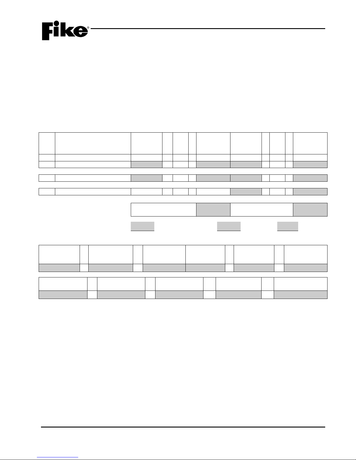
APPENDIX A
Section 1 - System Requirements
Total System
Unit (Amps)
Total System
Unit (Amps)
1
10-2622 System Controller (CSC)
0.116
x 1 =
0.116
0.176
x 1 =
0.176
2
Signaling Line Circuits (SLC)
x 1 =
x 1 =
Section 2 Totals
3
Auxiliary Power
x 1 =
x 1 =
4
Notification Circuits [Note 8]
NA
x
NA = NA
x 1 =
Section 4 Totals
Max. Quiescent Load (Standby):
hr
Total Alarm Load:
min. x 1/60 =
hr
Power c a lcul ati ons must be completed to deter m ine standb y and alarm current lo ads f or the system to assure
that the system power s upply is capable of providing the require d quantity of power during normal system
operation and fire alarm conditions. The power requirements cannot exceed t he capabilities of the system
power supply. Amp-hour requirements must be calc ulated as well to determine proper back -up battery size
selection.
The following battery calculation form provides the current draw (standby and alarm) of each compatible
device that can be connec ted to the system. To c alculate the required stan dby and alarm power, as well as
required back-up battery size for the system, simply list the number of each type of device that will be
connected to the system in the quantity column(s) and perform the required calculations.
BATTERY CALCULATION FORM
Item Description
Section 3 Totals
Required
Standby Time
(hr)
Required Standby
Capacity (Amp-hr)
+ = x =
Total System
Standby Current
x =
Current per
Unit (Amps)
[Note 4]
(Amps)
Required Alarm
Capacity (Amp-hr)
Standby
[Note 1]
Total System Standby
Standby Capacity
Current (Amps):
Required
(Amp-hr)
Total Required
Capacity (Amp-hr)
Qty
Required Alarm
Standby
Current per
Time (hr)
Alarm
Current per
Unit (Amps)
[Note 2 & 3]
[Note 2]
[Note 5]
Total System
Alarm Current
(Amps)
x =
Optional Factor of
Safety
[Note 6]
Total System Alarm
Current (Amps):
Qty
Current per
Required Alarm
Capacity
(Amp-hr)
Adjusted Battery
Capacity (Amp-hr)
[Note 7]
Alarm
Notes:
1. Auxiliary Power cannot exceed 1.75 A in normal standby condition.
2. Auxiliary Power plus Notification Power cannot exceed 5.25 A.
3. Auxiliary Power does not include current delivered to SCM during alarm conditions. This current is totaled in Section 4.0 Notification Appliances.
4. NFPA 72 requires that t he secondary power supply have sufficient capacit y to operate the system under no n-al arm co ndi tio n for a minimum of 24
hours. Alternate standby times may be required by the local authority or approval agency.
Factory Mutual re quires that the seconda ry Power Supply have suffic ient capacity to operate th e system under non-alarm condition for the
following systems Standard System 24 hours, Voice Evacuation 24 hours, Pre-Action/Deluge Release 90 hours.
5. NFPA 72 requires that at the e nd of the 24 hour standb y period, the s econda ry power su pply shall hav e sufficie nt capacit y to operate al l alarm
notification ap pliances used for evacuation or to direct aid to the location of an em ergency for 5 mi nutes (0.083 hr) s tandard, 15 minutes for
emergency voice/alarm communication service or UL 2572 mass notification service.
Factory Mutual requi res that at the en d of the required st andby perio d, the secon dary Power Suppl y shall have suf ficient capaci ty to operate all
alarm notification appliances used for or to direct aid to the location of an emergency for 5 minutes (0.083 hr) standard, 15 minutes for
emergency voice/alarm communication service and 15 minutes Pre-Action/Deluge Release.
6. 1.2 represents a batter y derating factor of 20 percent.
7. Cheetah Xi 50 control panel can support charging up to 75 AH standby batteries.
8. Section 4.0 shall onl y include the cu rrent dr aw of notifi cation appl iances powered b y the Cheet ah Xi 50 system controll er. This inclu des the t wo
on-board notification appliance circuits (NAC 1 & 2).
UL S2203 Cheetah Xi 50 Installation Manual A-1
FM P/N: 06-369 Rev 6, 09/2015
Page 62
APPENDIX A
Section 2 – Signaling Line Circuit
Standby
Unit (mA)
Total Standby
Unit (mA)
Alarm
Unit (mA)
Total Alarm
Unit (mA)
1
63-1052/1058 Photo
0.481
x = 2.000
x = 2
67-033/034 Ion
0.481
x = 2.000
x = 3
63-1053/1059 Photo/Heat
0.481
x = 2.000
x = 4
60-1039/1040 Heat
0.451
x = 2.000
x = 5
63-1057/63-1062 Photo/Duct
0.481
x = 2.000
x = 6
68-140 FAAST
0.300
X = 0.650
x =
8
55-045/050 MMM
0.485
x = 2.000
x = 9
55-041/046 MM
0.485
x = 2.000
x = 10
20-1063/1064 Pull Station
0.370
x = 2.000
x = 11
20-1343 Release Pull Station
0.370
x = 2.000
x = 12
55-042/047 SCM [Note 2]
0.630
x = 2.000
x = 13
55-043/048 RM
0.580
x = 2.000
x = 14
63-1063 Relay Base
0.170
x = 0.170
x = 15
55-052/053 RCM [Note 3]
0.450
x = 6.000
x = 16
63-1064 Sounder Base
0.300
x = 0.300
x =
18
02-3869 Remote Test
NA
x
NA = NA
10.000
x =
19
02-4998 Remote Key Test
NA
x
NA = NA
12.000
x =
Total SLC Standby (mA):
/1000 =
A Total SLC Alarm (mA):
/1000 =
A
Total
Total
Insert totals in Section 1 – Line Item 2.
Addressable Device Description
Item
[Note 1]
Current per
Qty
Current per
Current per
Qty
Current per
7 68-302 FAAST XT [Note 1] 0.465 X = 0.493 x =
[Note 1]
17 02-3868 Remote Annunciator NA x NA = NA 10.000 x =
Total SLC Standby
Current (mA):
Total SLC Alarm
Current (mA):
Notes:
1. Device requires 24vdc power for operation. Include d evice current draw in Section 3. 0 if power is supplied by the Cheetah Xi 50 system
controller.
2. Device requires 24vdc po wer f or operati on of connect ed devices. If using the SCM to control t he operatio n of master-box interface or sprink ler
solenoids, include c urren t dra w for all c onn ected d evice s in Secti on 3 .0. If usi ng the SC M to con trol noti ficati on a ppli ances, i nclud e curre nt dra w
for all connected devices in Section 4.0.
3. Device requires 24vdc power for operation of connected releasing device(s). Include current draw for all connected devices in Section 3.0.
A-2 Cheetah Xi 50 Installation Manual UL S2203
Rev 6, 09/2015 P/N: 06-369 FM
Page 63
APPENDIX A
Section 3 – Auxiliary Power
Total
Unit (Amps)
1
68-140 FAAST
0.500
x = 0.650
x =
2
68-302 FAAST XT
0.500
x = 0.650
x =
3a
10-1832 ARM [Note 2]
0.002
x = 0.008
x =
3b
10-2748 IRM
0.003
x = 0.037
x =
4
55-052/053 RCM w/ Solenoid
0.0364
x = 0.010
x =
4a
Releasing Solenoid Coil [Note 3]
NA
x
NA = NA
x =
55-042/047 SCM w/ Solenoid
[Note 3]
6
10-2413 Master-box Supervisor
0.022
x = 0.283
x =
7
63-1064 Sounder Base
0.007
x = 0.027
x =
8
10-2528/-2476 DACT
0.150
x = 0.190
x =
10
10-2631 10-button RDU
0.036
x = 0.139
x =
11
10-2646 14-button RDU
0.036
x = 0.139
x =
12
10-2627 Ethernet Module
0.097
x = 0.134
x =
13
10-2583 Multi-Interface
0.200
x = 0.200
x =
14
10-2411 LED Graphic Micro
0.067
x = 0.140
x =
15
10-2667 20-Zone Remote Annun.
0.051
x = 0.148
x =
17
10-2777 Relay Assy. [Note 4]
0.047
x = 0.109
x =
18
10-2204 CRM4 Relay
0.011
x = 0.040
x =
20
10-2792 Class A Peripheral
0.057
x = 0.057
x =
21
10-2814 LOC Digital Paging
0.103
x = 0.140
x =
22
10-2616 Keltron Printer
0.200
x = 1.200
x =
23
10-2277 VESDA HLI
0.245
x = 0.245
x =
Insert totals in Section 1 – Line Item 3.
Item Device Description
Standby
Current per
Unit (Amps)
Qty
Current per
Standby
Alarm
Current per
Unit (Amps)
Qty
Total Alarm
Current per
Unit (Amps)
3 55-052/053 RCM w/ Agent 0.0194 x = 0.010 x =
[Note 2]
5
NA x NA = NA x =
6a Master-box Trip Coil [Note 3] NA x NA = NA x =
9 10-2630 2-button RDU 0.036 x = 0.139 x =
16 10-2785 Relay Card [Note 5] 0.032 x = 0.256 x =
[Note 5]
19 10-2770 HPM4 Relay [Note 5] NA x NA = NA 0.086 x =
Total Aux. Power Standby
Current (Amps):
Total Aux. Power Alarm
Current (Amps):
Notes:
1. Indicate the current draw of the devices in this section only if the 24vdc power for device operation is supplied by the Cheetah Xi 50 system
controller. Typical for all devices.
2. Indicate quantity of ARMs or IRMs connected to the RCM.
3. Indicate alarm current draw of the coil that is connected to the module.
4. Assembly includes control card and relay bus card. Add the quantity of CRM4 and HPM4 relay cards installed on the bus card in rows 18 and
19.
5. Current values shown assume all relays are active.
UL S2203 Cheetah Xi 50 Installation Manual A-3
FM P/N: 06-369 Rev 6, 09/2015
Page 64
APPENDIX A
Section 4 – Notification Appliances
Total Alarm
Unit (mA)
1
x =
2
x =
3
x =
4
x =
5
x =
7
x =
8
x =
9
x =
10
x =
11
x =
12
x =
13
x =
14
x =
15
x =
17
x =
18
x =
19
x =
20
x =
21
x =
22
x =
23
x =
25
x =
26
x =
28
x =
29
x =
30
x =
31
x =
32
x =
33
x =
34
x =
35
x =
36
x =
38
x =
Total NAC Alarm (mA):
/1000 =
A
Total
Insert totals in Section 1 – Line Item 4.
Item Device Description
6 x =
16 x =
Alarm Current per
Unit (mA)
Qty
Current per
27 x =
37 x =
Total NAC Power Standby Current (Amps):
Notes:
1. Include current draw of all notification appliances connected to the Cheeta h Xi 50’s two on-board notification appliance circuits (NAC 1 & 2), and
to addressable Supervised Control Modul es that ar e rec eiving 24vdc power from the Cheetah Xi 50 system controller.
A-4 Cheetah Xi 50 Installation Manual UL S2203
Rev 6, 09/2015 P/N: 06-369 FM
Page 65

APPENDIX B
The “System Operation Posting” shown on the following pages provides a brief summary of the basic
operation of the Cheetah Xi 50 system. The operati onal posting can also be downloaded fr om Fike Forums
web page (document P/N 06-650). For a detailed description of the op eration of the Cheetah Xi 50 system,
refer to Fike document 06-369-2, “Cheetah Xi 50 Operation and Maintenance Manual” for more details.
The completed “System Operation Posting” shall either be mounted on the cabinet front or framed and
located adjacent to the control unit.
UL S2203 Cheetah Xi 50 Installation Manual B-1
FM P/N: 06-369 Rev 6, 09/2015
Page 66

APPENDIX B
Reserved for future use.
B-2 Cheetah Xi 50 Installation Manual UL S2203
Rev 6, 09/2015 P/N: 06-369 FM
Page 67
OPERATING INSTRUCTIONS
Cheetah Xi 50 Control System
(P/N 10-071)
Commercial Protected Premises Control Unit
Local, Remote Station (PPU), Central Station (PPU), and Releasing Service
These instructions must be framed and displayed next to the panel in accordance with NFPA 72, National Fire Alarm Code
for Local Fire Alarm System.
The key to open the panel can be found at this location:
____________________________________________
1.0 OPERATING INFORMATION
Normal Standby
1. Green AC Power LED lit steady.
2. All notification appliances off.
System Alarm
1. Red Alarm LED flashes.
2. Local piezo pulses.
3. Alarm notification appliances on.
4. Alarm information visible on LCD (liquid crystal display).
5. DO NOT press the RESET key at this time.
6. Press the ACKNOWLEDGE key to turn off the local
piezo. Flashing LEDs will illuminate steady after key
press.
7. Press the SILENCE key to turn off the local piezo and
silence active notification appliances programmed for
silence.
8. Press the F1 key to display the source of the event on
the top line of the LCD (liquid crystal display).
9. Investigate the source of the alarm condition and take
appropriate actions.
10. After correcting the Alarm condition, press the RESET
key to restore the system to normal operation.
System Trouble/Supervisory
1. Yellow Trouble and/or Supervisory LED flashes.
2. Local piezo pulses.
3. Trouble and/or Supervisory audible(s) on.
4. Trouble and/or Supervisory information visible on LCD
(liquid crystal display).
5. DO NOT press the RESET key at this time.
6. Press the ACKNOWLEDGE key to turn off the local
piezo. Flashing LEDs will illuminate steady after key
press.
7. Press the SILENCE key to turn off the local piezo and
silence active notification appliances programmed for
silence.
8. Press the F1 key to display the source of the event on
the top line of the LCD (liquid crystal display).
9. Investigate the source of the Trouble/Supervisory
condition and take appropriate actions.
10. After correcting the Trouble/Supervisory condition, press
the RESET key to restore the system to normal
operation.
Trouble Condition – Activation of a trouble signal under
normal operation indicates a problem with the system (not an
alarm) that requires immediate attention. Contact your local
service representative. In most trouble conditions, the fire
suppression system continues to provide protection to the
building and its occupants; however, trouble conditions
should not be allowed to remain and should be investigated
and remedied as soon as possible to ensure proper sys tem
operation.
2.0 HISTORY AND CONTROL BUTTONS
Step Alarm – Steps through the current ALARM events
stored in the panel’s Alarm history buffer. Available only if
there are active alarm events present on the system.
Step Super – Steps through the current SUPERVISORY
events stored in the panel’s Supervisory history buffer.
Available only if there are active supervisory events present
on the system.
Step All - Steps through ALL events stored in the panel’s
current event history buffer. Press the F5 key to toggle
between current events and the panel’s entire 3,200 event
history buffer.
Drill – Manually activates all outputs and notification
appliances circuits assigned for drill operation in the
configuration. Press the RESET key to clear the drill
activation. Displays drill activation on LCD (liquid crystal
display).
Acknowledge – Silences the local piezo sounder and
changes all flashing LEDs to steady. All outputs remain
active. Creates an acknowledge event in the panel history
buffer.
Silence – Silences the local piezo sounder and all
silenceable circuits. Illuminates the Yellow SILENCE LED
steady and creates a silence event in the panel history buffer.
Reset – Resets the control panel to normal operation. All
active control functions (relays and NACs) will deactivate. All
display LEDs will illuminate steady until reset is complete. If
events are still present on the system, control functions will
immediately activate.
Enter – Saves and enters the current configuration settings.
Use navigation buttons to change variables at the blinking
cursor position.
Escape – Toggles event display from OFF-NORMAL (events
present) to SYSTEM NORMAL (no events present) to TOP
LEVEL menu.
Function Keys (F1 – F6) – Used to navigate through the
control panel’s menu system during system operation,
maintenance and configuration.
Page 68

3.0 LED INDICATORS
AC Pow er – Green LED which illuminates when AC power is
applied to the control panel. Turns off when the AC power is
removed or is too low for proper operation.
Alarm – Red LED that flashes when the panel enters the
Alarm state. Illuminates steady after you acknowledge or
silence the event. Turns off after the event is cleare d and the
control panel is reset.
Trouble – Yellow LED that flashes when the panel enters the
Trouble state or if a zone or device is disabled. Illuminates
steady after you acknowledge or silence the event. Turns off
when all trouble conditions are cleared.
Supervisory – Yellow LED that flashes when the panel
enters the Supervisory state or if a zone or device is disabled.
Illuminates steady after you acknowledge or silence the
event. Turns off when all supervisory conditions are cleared.
Silence – Yellow LED that illuminates steady after a
SILENCE switch is pressed (local or remote). Turns off when
DRILL or RESET key is pressed.
Pre-discharge – Red LED that flashes when the panel enters
the Pre-discharge state. Illuminates steady after you
acknowledge or silence the event. Turns off when t he panel
is reset.
Release – Red LED that flashes when the panel enters the
Release state. Illuminates steady after you acknowledge or
silence the event. Turns off when the panel is reset.
Disable – Yellow LED that illuminates steady when any zone
is disabled. Outputs in the disabled zone will not operate.
Panel will also indicate a Trouble and Supervisory event
when a zone is disabled. Turns off when the panel is reset or
the zone is enabled.
Abort – Yellow LED that flashes when the panel enters the
Abort state. Illuminates steady after you acknowledge or
silence the event. Turns off if the abort condition clears and
no other abort events are present.
Ground Fault – Yellow LED that illuminates steady when a
ground fault condition is present on the system. Turns off
when the ground fault is cleared or the panel is reset.
4.0 MAINTENANCE AND TESTING
To ensure proper and reliable operation of the system,
system inspection and testing should be scheduled as
required by NFPA 72 and local cod es and standards. Only a
qualified Service Representative should perform testing or
system maintenance.
Before Testing: Notify the fire department and/or central
alarm receiving station if alarm conditions are transmitted offsite. Notify facility personnel of the test so alarm notification
appliances are ignored during the test period. Physically
disconnect all releasing devices.
Before Servicing: Remove AC and battery power before
performing any repair or service work on the control panel.
Refer to Fike document 06-369-2, “Cheetah Xi 50 Operation
and Maintenance Manual” for maintenance instructions.
5.0 IN CASE OF TROUBLE CONTACT:
Name:___________________________________________
Address:_________________________________________
Phone #:_________________ ________________________
or Fike Corporation
Customer Service Department
(800) 979-FIKE (3453) or
(816) 229-3405
Refer to Fike document 06-369-2, “Cheetah Xi 50
Operation and Maintenance Manua l ” for additional
information.
Page 69

APPENDIX C
Part Number
Description
PERIPHERAL BUS DEVICES
C.1 COMPATIBLE COMPONENTS
The following table iden tifies the compone nts that are com patible with t he Cheetah Xi 50 s ystem . Onl y thos e
items listed shall be used on the system.
Exhibit C-1: Compatible Components
10-2622 Cheetah Xi 50 Control Board (included with 10-071 system)
10-2623-c
or
10-2623-c-d
10-2628-c
02-10881 Transformer, 120VAC primary
02-10882 Transformer, 240VAC primary
10-2528 DACT (Bosch FPT-DACT-LC), 5 zone with Serial interface-for internal mountin g
10-2476 DACT (Bosch F PT-DACT), 5 zone with Serial interface-w/enclosure for external mounting
10-2646 14-Button Expanded Protocol Remote Display Unit
10-2631 10-Button Expanded Protocol Remote Display Unit
10-2630 2-Button Expanded Protocol Remote Display
10-2627 Ethernet Module
10-2583 Multi-Interface Module
10-1XXX Intelligent LED Graphic Annunciators
10-2667 20 Zone Remote Annunciator Module
10-2777 Relay Control Assembly (includes P/N 10-2778 Control Card and P/N 10-2769 Bus Card)
10-2785 Relay Card (RC12)
10-2792 Class A Peripheral Bus Card
Cheetah Xi 50 Enclosure (included with 10-071 system)
c: (R=Red, B=Gray)
d: specifies enclosure equipped with optional dead-front
Dead-front Panel, c: (R=Red, B=Blac k)
OPTIONAL MODULES
UL S2203 Cheetah Xi 50 Installation Manual C-1
FM P/N: 03-369 Rev 6, 09/2015
Page 70

APPENDIX C
Part Number
Description
INTELLIGENT DETECTORS
63-1052
Photoelectric Detector
67-033
Ionization Detector
63-1053
Photo/135° F Heat Combination Detector
60-1039
Intelligent Heat Detector, 135°-190° F (57°-88° C) Fixed Temp./ Rate of Rise
63-1054 (EBF)
Detector Base, 6 inch (System Sensor)
63-1055 (EB)
Detector Base, 4 inch (System Sensor)
63-1064 (EBS)
Sounder Base, 6 inch (System Sensor)
63-1063 (EBR)
Relay Base, 6 inch (System Sensor)
63-1058
Photo Detector, with Isolator
67-034
Ionization Detector, with Isolator
63-1059
Photo/135° F Heat Combination Detector, with Isolator
60-1040
Heat Detector, 135°-190° F (57°-88° C) Fixed Temp./ Rate of Rise, with Isolator
63-1060 (EBFI)
Detector Base, 6 inch, with Isolator (System Sensor)
63-1061 (EBI)
Detector Base, 4 inch, with Isolator (System Sensor)
63-1057
Photo DUCT detector
63-1062
Photo DUCT detector, with Isolator
63-1158
DUCT Detector Housing (must be used with 63-1057 & 63-1062)
68-140
FAAST Aspirating Smoke Detector
68-302
FAAST XT Aspirating Smoke Detector
DUCT DETECTOR ACCESSORIES
02-3868
Remote Annunciator LED
02-3869
Remote Test Station
02-4998
Remote Test Station with Key
63-1159
Sampling Tube, Duct Detector, up to 1 ft. (0.3m)
63-1160
Sampling Tube, Duct Detector, 1 ft. to 2 ft. (0.3m – 0.6m)
63-1161
Sampling Tube, Duct Detector, 2 ft. to 4 ft. (0.6m – 1.2m)
63-1162
Sampling Tube, Duct Detector, 4 ft. to 8 ft. (1.2m – 2.4m)
63-1163
Sampling Tube, Duct Detector, 8 ft. to 12 ft. (2.4m – 3.7m)
ADDRESSABLE MODULES
55-045
Mini Monitor Module (MMM)
55-041
Monitor Module (MM), 4 inch
20-1063
Addressable Pull Station (APS)
55-042
Supervised Control Module (SCM)
10-2360
Series Solenoid Diode/Resistor
10-2413
Master-box Interface
55-043
Relay Module (RM)
55-052
Releasing Control Module (RCM)
55-050
Mini Monitor Module (MMM), with Isolator
55-046
Monitor Module (MM), 4 inch, with Isolator
20-1064
Addressable Pull Station (APS), with Isolator
55-047
Supervised Control Module (SCM), with Isolator
55-048
Relay Module (RM), with Isolator
55-053
Releasing Control Module (RCM), with Isolator
Exhibit C-2: Compatible Components – Cont.
C-2 Cheetah Xi 50 Installation Manual UL S2203
Rev 6, 09/2015 P/N: 03-369 FM
Page 71

APPENDIX C
Part Number
Description
VESDA INTERFACE
Exhibit C-3: Compatible Components – Cont.
68-023 VESDA Open Protocol High Level Interface (HLI)
PROGRAMMING AND CONFIGURATION
55-051 Infrared (IR) Tool Remote Control for Programming/Testing Devices (non-listed)
10-2648 Cheetah Xi Addressable Device Hand Held Programmer (non-listed)
06-327 C-Linx Software (non-listed)
10-1874A Interface Cable for C-Linx Software (DB9 to RJ11)
10-1874B USB to DB9 Converter (02-11139) with 10-1874A interface cable
Provides ability to use USB serial port on laptop (USB-DB9-RJ11)
02-11139 USB to DB9 Converter (02-11139) without 10-1874A interface cable
10-2629 USB A/B Cable for configuration of Cheetah Xi 50 System
10-2477 DACT Programmer (Bosch FMR-DACT-KEYPAD)
BATTERIES AND BATTERY ENCLOSURES
10-2626 12 AH Battery Assembly w/ wiring assembly
10-2190-2 18 AH Battery Assembly w/ wiring assembly
10-2192 Wiring Assembly for 7.2 AH and 18 AH Batteries (wire only)
10-2517 Wire Assembly with Battery EOL
02-2018 Battery, 12V, 7 AH (Requires 2 each)
02-4622 Battery, 12V, 12 AH (Requires 2 each)
02-2820 Battery, 12V, 18 AH (Requires 2 each)
02-3468 Battery, 12V, 33 AH (Requires 2 each)
A02-0252 Battery, 12V, 40 AH (Requires 2 each)
02-4206 Battery, 12V, 75 AH (Requires 2 each)
10-2154-R 33 AH Battery Enclosure, Red, no batteries
10-2154-B 33 AH Battery Enclosure, Black, no batteries
10-2236-R 75 AH Battery Enclosure, Red, no batteries
10-2236-B 75 AH Battery Enclosure, Black, no batteries
UL S2203 Cheetah Xi 50 Installation Manual C-3
FM P/N: 03-369 Rev 6, 09/2015
Page 72
APPENDIX C
Part Number
Description
Exhibit C-4: Compatible Components – Cont.
SPARE PARTS
02-4035 Hardware Kit, #6 lock washers and hex nuts (30 each)
02-10788 Standoff kit, 5/8” M/F, 5 each required for DACT (10 each supplied)
02-4009 Standoff, 2” M/F, for Cheetah Xi 50 controller, 4 each required (1 each supplied)
02-11751 Standoff, 2” F/F, for Cheetah Xi 50 controller, 1 each required (1 each supplied)
02-11823 Key lock with cam
02-4983 Panel Key Only (without cam)
02-10881 Transformer, 120VAC
02-10882 Transformer, 240 VAC
02-4040 Battery, Lithium Coin Cell, 3V
10-2625 Monitor and Control Module EOL Assembly, 39K
10-2530 14KΩ Series Resistor, for Monitor Module Short Circuit detection
10-2570 End of Line Resistor, 1.2 K (for NAC 1 & 2)
02-4174 Fuse, 15 Amp, Mini-Auto, Fast Acting (For F1 & F2) (Little fuse p/n 297015)
02-11412 Fuse, 4 Amp, Mini-Auto, Fast Acting (For F3-5) (Little fuse p/n 297004)
02-4981 End Of Line Relay – System Sensor EOLR-1
02-2519 Termination Resistor, 100 ohm (for RS485 circuit)
02-11723 Bezel, Outer Door
C.1.1 TOUCH-UP PAINT (NOT AVAILABLE FROM FIKE)
Sherwin Williams, Signal Red – RAL 3001 per RAL 840-HR (Matt Finish)
Sherwin Williams, Light Gray – RAL 7035 per RAL 840-HR
C.1.2 NOTIFICATION APPLIANCES
Refer to Fike document 06-186 for compatible notification appliances.
C.1.3 APPROVED RELEASING DEVICES
Refer to Fike document 06-186 for compatible releasing devices.
C-4 Cheetah Xi 50 Installation Manual UL S2203
Rev 6, 09/2015 P/N: 03-369 FM
Page 73
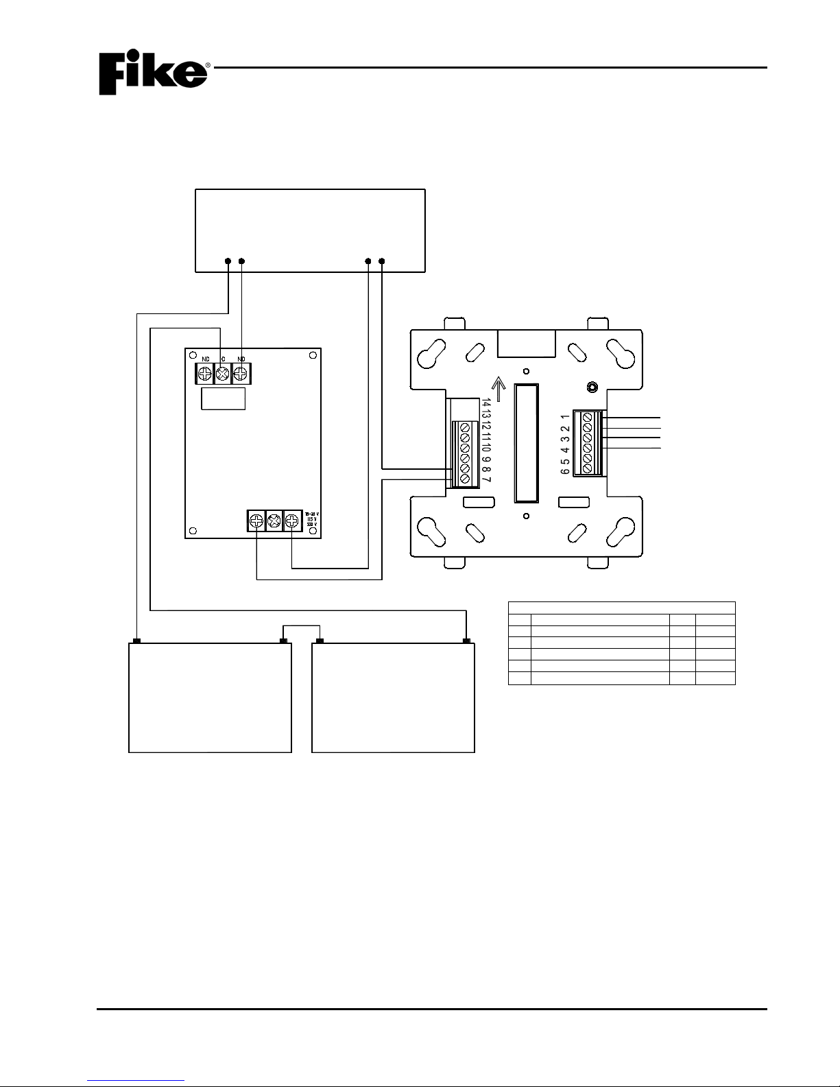
APPENDIX D
TOP
LOOP ADDRESS
RELAY
MULTI VOLTAGE RELAY
P/N 20-1173
BATTERY BATTERY
24 VDC AUXILIARY
POWER OUTPUT
BATTERY
CONNECTION
CONTROL PANEL
RELAY MODULE TERMINAL DEFINITIONS
T1 (+) SLC IN/OUT T7 NC #1
T2 (-) SLC IN/OUT T8 C #1
T3 (+) SLC IN/OUT T9 NO #1
T4 (-) SLC IN/OUT T10 NC #2
T5 (+) DRY CONTACT INPUT T11 C #2
T6 (-) DRY CONTACT INPUT T12 NO #2
SLC IN
SLC OUT
OR
P/N 20-1177
D.1 BATTERY CUTOFF
Exhibit D-1 below shows the com ponents used to f acilitate the batter y cutoff arr angement for Fik e’s Cheetah
Xi 50 control panel.
UL S2203 Cheetah Xi 50 Installation Manual D-1
FM P/N: 06-369 Rev 6, 09/2015
Exhibit D-1: Battery Cutoff Wiring Diagram
Page 74

APPENDIX D
Reserved for future use.
D-2 Cheetah Xi 50 Installation Manual UL S2203
Rev 6, 09/2015 P/N: 06-369 FM
Page 75

Page 76

704 SW 10th Street
P.O. Box 610
Blue Springs, Missouri 64013
Tel: (816) 229-3405
Fax: (816) 229-0314
www.fike.com
 Loading...