

Page 1

190102A2
Page 2
General Notes
• Please read the following operating instructions very carefully before using this fixture for the
first time. They contain important information on the operation of Fiilex lighting equipment.
• For your own safety, please follow all safety instructions and warnings.
• Please also follow the operating instructions of the light and power adapter manufacturers.
• Keep these operating instructions for you and subsequent users for future reference.
• For further information, contact Fiilex ([email protected]) or your retailer.
Basic Operation (refer to Parts Diagram on following page)
• Turning On
The P360 Gen II Series comes with a power adapter. To supply the fixture with power, insert the
connector into the DC Power Input Jack (9), then connect the DC plug into an active wall socket.
For P360 Pro and P360 Pro Plus fixtures, the OLED Display (15) will turn on once it is receiving
power. The On/Off Button (10) toggles the fixture’s output on and off. Settings can still be adjusted while the switch is set to off.
• Positioning
Use the Yoke Knobs (5) to lock the fixture’s tilt position. Tighten the handle to secure.
• Mounting
The Light Stand Adapter (14) on the P360 Gen II Series can be mounted to a Baby or Junior Stand
with combo pin. Secure the fixture to the stand by turning the tightening knob.
• DMX Interface (Pro / Pro Plus only)
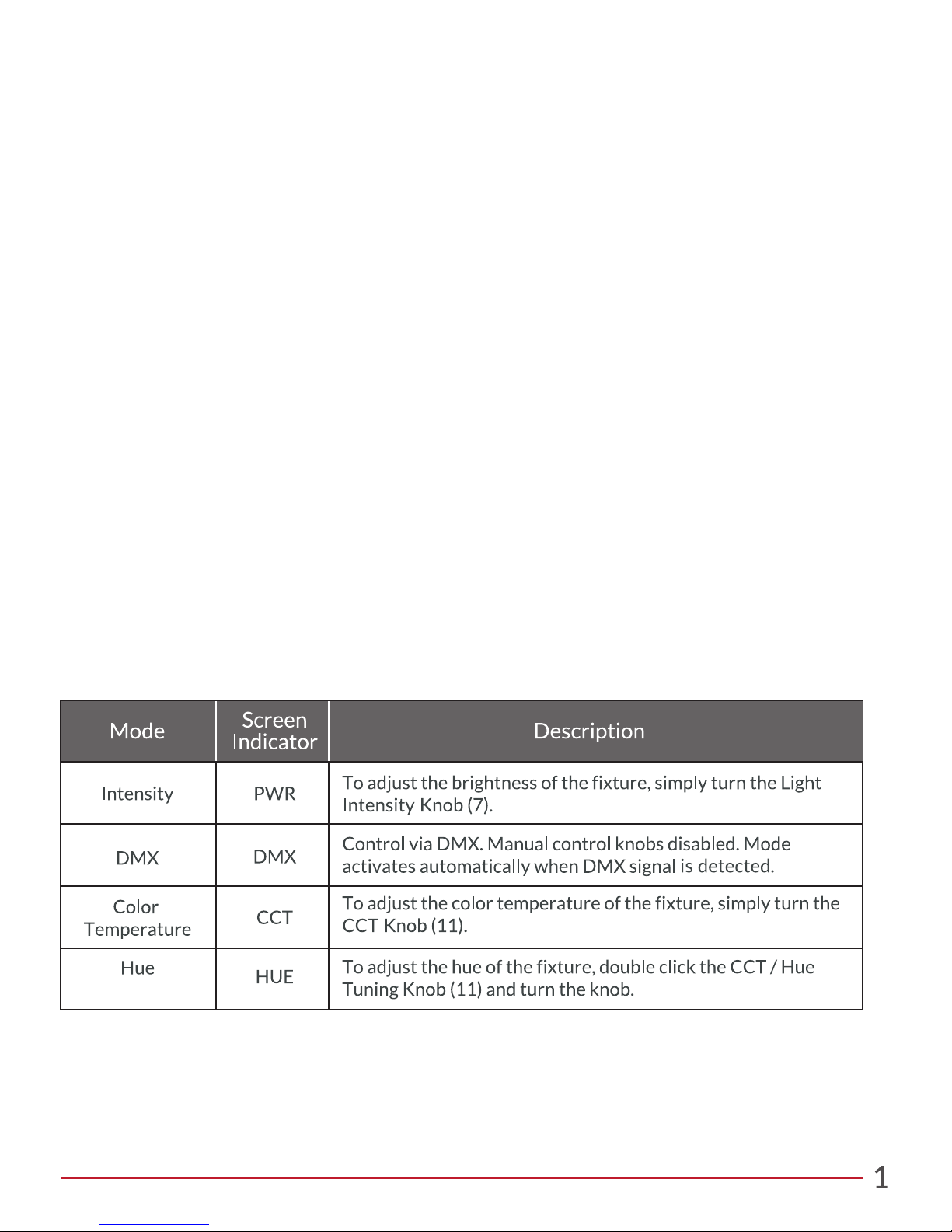
Insert the phone jack (TRRS) connector into the Light Control Input Jack (12). Double click the
DMX Address Knob (7) to enter DMX address edit mode. Turn the knob to select desired
address. To return to intensity adjustment mode, click the knob (7) again or wait 3 seconds.
*
**
(Magenta/Green)
* Available in Pro and Pro Plus Models
** Available in the Pro Plus Model
Page 3

Parts Diagram
Mounting the Light
Attach Light Stand
Adapter (14) to a
baby/junior stand
with combo pin.
Secure the light by
tightening the locking
knob.
Installing Barndoors
Slide Barndoors into
the Barndoor Brackets
(2) until the Accessory
Lock (3) clicks.
Releasing Barndoors
To release the
Barndoors, slide the
Accessory Lock
Release (16) and slide
the Barndoors out of
the Brackets (2).
Plugging In
Insert the DC connector into the DC power
jack.
Powering On
Press the On/Off
button to turn on the
light. The button will
turn green to indicate
that the light is on.
Page 4

Rear Panel Interface & Operation
P360 Pro Plus
P360 Pro
Assigning DMX Address:
Knob
CCT
PWR
HUE
DMX
Function
Set color temperature
Set intensity
Set HUE value
Set DMX address
± 0.25 Magenta/Green
Range
2800K - 6500K
100% - 0.1%
1 - 510
1. Double click the DMX Address Knob (7) to display the DMX
address setting screen on the OLED Display (15).
2. Rotate the knob to select the desired base address (1-510).
3. Once desired address is displayed on the screen, lock in the setting
by clicking the knob once. Alternatively, the address will automatically lock in after 1 second of inactivity.
4. When a DMX address is selected, the fixture will automatically
assign the next one/two addresses in the following order:
• Pro Plus: (1) Intensity (2) CCT (3) Hue
• Pro: (1) Intensity (2) CCT
• For adjusting the fixture’s DMX address via RDM, consult the
operating instructions for DMX/RDM control systems.
Specifications
Light Engine
Power Draw
Size (L x W x H)
Thermal Design
Operating Temperature
LED Lifetime
Certifications
CCT Range
DC Input
AC Input
Power Port
DMX Ports
Weight
Mount
IP Rating
2800 - 6500K Continuous Tuning
Dense Matrix LED
90W Max
12 - 30V (80W DC Max)
100 - 240V AC, 50 ~ 60Hz
2.5mm DC Jack
TRRS (In & Out) *Pro and Pro Plus models only*
1.9lbs / 0.8kg
5.9in x 4.7in x 8.1in / 15.0cm x 11.9cm x 20.6cm
Baby Stud 5/8” Female (16mm)
Advanced Vapor Cooling System (Fan Cooled)
32 - 104ºF / 0 - 40ºC
IP-24
42,000 hours
CE, UL, FCC
Page 5
 Loading...