

Page 1

Figure Engineering
9208 Venture Ct – C9
Manassas Park VA 20111
[email protected]
www.FigureLLC.com
Installation Manual
2006-PRESENT DODGE CHARGER
FIGURE GRILLE SET
Page 2

3
Dear Customer,
Thank you for purchasing Figure’s 2005-Present Dodge
Charger Grille set. These grilles are fabricated employing
quality materials and finishes, and have been engineered to
enhance the look of your vehicle for the duration of its life.
Proper installation is essential to your overall satisfaction, so
please read these instructions before attempting to install the
grilles. Exercise patience; these instructions are intended to
assist even the most mechanically challenged.
Remember, if you are not 100% satisfied with our product,
simply return the set to us (or to the retailer if you did not
purchase directly through Figure) within 30 days of purchase
for a complete refund.
We always love to see pictures of the installed grilles, so we
encourage you to email us your best! (Send to
Package Contents:
QTY(2) Upper Grilles
QTY(2) Lower Grilles
*QTY(1) Full-Width Lower Grille
QTY(30) Nylon Ties, 4” (High-tensile-strength, UV-resistant)
*QTY(10) Tie Mounts (22 gage galvanized steel wire)
QTY(1) Instruction Manual
Tools Required for Installation:
Angle cutters (snip pliers)
Drill
Drill bit, 1/8” & *1/16”
Screwdriver, medium slotted
Screwdriver, small slotted
Screwdriver, low-profile Philips (Fig. 1)
*Needle nose pliers
* With full-width lower grille option.
Page 3

4
Dodge Charger Figure Grille Installation
Figure 1. Examples of low-
profile Philips screwdrivers.
1) Ratchet (¼” drive) with
¼” socket and Philips bit.
2) Offset Philips
screwdriver.
1.1) Remove radiator covers. Begin by popping the hood
of your vehicle. There are two plastic protective shields
which cover the radiator area. These are held in place by
small clips which will let go easily by pulling on the pieces.
Fig. 2 shows these covers and illustrates their removal.
Figure 2. Removal of radiator covers.
Page 4

5
1.2) Remove the grille frame screws. The grille assembly
consists of two pieces, the grille frame and the grille (Fig. 3).
Both must be removed from the vehicle to release the grille.
Figure 3. Grille assembly comprising a grille frame (above) and grille.
Use a low-profile Philips screwdriver (Fig. 1) to remove the
four screws that secure the grille assembly to the bumper.
The locations of these screws are shown in Fig. 4.
Figure 4. Locations of grille assembly screws.
Page 5

6
1.4) Remove grille assembly from bumper. Once the four
screws are removed from the grille assembly, the grille
frame is still held in place by four tabs along its perimeter.
These tabs are visible from inside the engine compartment
(Fig. 5). Insert a slotted screwdriver between the grille
frame and the bumper at the outside of the vehicle (Fig. 6.),
and gently pry the grille frame from the bumper by freeing
each of the four tabs as you work your way around the grille
frame.
Figure 5. The tabs securing the grille frame to the bumper are visible
from inside the engine compartment.
Figure 6. Use a slotted screwdriver to gently pry the grille frame from
the bumper. Helpful hint: Wrap the screwdriver with masking or
electrical tape to guard against scratches.
Page 6

7
1.5) Separate the grille from the grille frame. First free
the outsides of the grille from the frame by inserting a slotted
screwdriver between the grille and the frame at the tab clips
(Fig. 7.1), and pry upward until the grill slot is free of the
retaining lip on the frame tab (Fig. 7.2).
Figure 7. Method of disassembling outer grille clips.
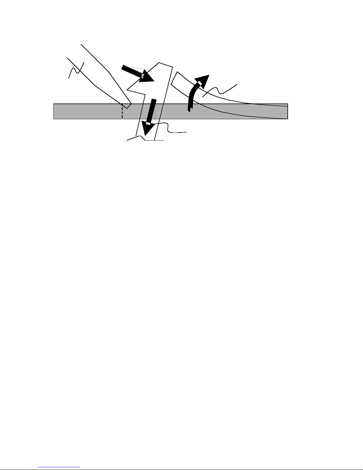
Next, use two slotted screwdrivers to free the inner clips, as
demonstrated in Fig. 8 and Fig. 9. The grille should now be
separated from the grille frame.
Figure 8. Method for disassembling inner grille clips.
Page 7
8
1
2
EAR TAB
GRILLE TAB
3
SCREW
DRIVER
1
2
EAR TAB
GRILLE TAB
3
SCREW
DRIVER
Figure 9. Method for freeing inner grille clips.
2) Prepare the grille frame for installation. Drill a 1/8”
hole in each of the sixteen frame tabs that held the stock
grille in place. Be sure to place the hole against the
retaining lip on the finished side of the lip, as shown in Fig.
10.
Note: The holes drilled in the frame do not affect the fit or
appearance of the stock grille, should you desire to reinstall
it in the future; the holes are completely hidden.
Figure 10. Drill a 1/8” hole on the finished side of the retaining lip. The
hole should touch the retaining lip.
Page 8

9
3) Install the grilles into the grille frame. Fit the grilles
into their respective openings and secure them with the
nylon ties, as shown in Fig. 11. Notice the grille backs up
against the retaining lip that secured the stock grilles. It may
be necessary to make minor adjustments to perfect the fit.
Clip the tails from the ties with angle cutters.
???WHY NYLON TIES??? Nylon ties have been selected
as the primary means of securing these grilles for two
reasons: 1) Nylon ties are nearly invisible on installed grilles,
providing a clean look. 2) The high-tensile-strength ties
provided are extremely strong, and surprisingly theftdeterrent, since they do not allow the grilles to be popped
out like the stock grilles; in order to break the ties, a thief is
required to access the engine compartment. These ties and
mounts are also UV- and weather-resistant for long life.
Figure 11. Grilles installed. The arrows point to where the grille seats
against the frame tabs’ retaining lip.
4) Install the optional full-width lower grille. Before
reinstalling the grille frame, you will need to install the lower
Page 9

10
grille, if you have selected this option. If you have not
selected this option, skip to Step 5.
The optional lower grille installs using eight pieces of 22
Gage galvanized steel.
4.1) Drill 1/16” holes, in the locations shown in Fig. 12
Drill these holes about 1/8” from the edge of the bumper
(see Figure 13) so that the install wires are nearly invisible
when secure. Place the grill against the inside edge of the
bumper and loosely attach each of the eight wires. When all
fasteners are loosely installed, use a pair of pliers to twist
each fully tight.
Figure 12. Locations to drill holes for lower grille option
Page 10

11
Figure 13. Location to drill holes for lower grille option
5.1) Modify the grille frame for reinstallation. The grille
frame must be modified since the stock grille, now removed,
held the grille to the bumper. Drill 1/8” holes in the grille
frame tabs (two for each of the four grille openings for a total
of eight) as shown in Fig. 14. Note the proper hole
placement on the larger tabs.
Figure 14. Location of grille frame mounting holes.
Page 11

12
5.2) Modify the bumper to accept the grille frame. Insert
the grille frame into the bumper opening and note the
location of the frame holes relative to the bumper. Drill holes
in the lip of the bumper in these locations as shown in Fig.
15.
Figure 15. Example of location of bumper holes. Note: Tabs on grille
frame are not symmetrical!
5.3) Install grille frame. Insert the grille frame into the
bumper opening, and use nylon ties to secure the grille in
the 8 locations at which you drilled the holes. Cut the tails
off the ties.
5.4) Reinstall the radiator covers. Install the driver’s side,
then the passenger’s side.
Page 12

 Loading...