

FIGARO TGS 832 User Manual

FIGARO
SUNSTAR传感与控制 http://www.sensor-ic.com/ TEL:0755-83376549 FAX:0755-83376182 E-MAIL:szss20@163.com
SUNSTAR自动化 http://www.sensor-ic.com/ TEL: 0755-83376489 FAX:0755-83376182 E-MAIL:szss20@163.com
TGS 832 - for the detection of Chlorofluorocarbons (CFC's)
PRODUCT INFORMATION
Features:
* High sensitivity to R-134a
Applications:
* Refrigerant leak detector
* Quick response to R-134a
* Improved selectivity
* Long term stability
* Uses simple electrical circuit
* Ceramic base resistant to severe
environment
The sensing element of Figaro gas sensors is a tin dioxide (SnO
which has low conductivity in clean air. In the presence of a detectable gas, the
sensor's conductivity increases depending on the gas concentration in the air. A
simple electrical circuit can convert the change in conductivity to an output signal
which corresponds to the gas concentration.
The TGS 832 has high sensitivity to R-134a, the most promising alternative to R-12,
commonly used in air conditioning systems and refrigerators. R-12 and R-22 are also
detectable by TGS 832. With its good long term stability, TGS 832 is an excellent,
low-cost sensor for CFC detection.
The figure below represents typical sensitivity char-acteristics,
all data having been gathered at standard test conditions (see
reverse side of this sheet). The Y-axis is indicated as
resistance ratio
(Rs/Ro) which is defined as follows:
sensor
Rs = Sensor resistance of displayed gases at
various concentrations
Ro = Sensor resistance at 100ppm of R-134a
2) semiconductor
The figure below represents typical temperature and humidity
dependency characteristics. Again, the Y-axis is indicated as
sensor resistance ratio
Rs = Sensor resistance at 100ppm of R-134a
Ro = Sensor resistance at 100ppm of R-134a
(Rs/Ro), defined as follows:
at various temperatures/humidities
at 20°C and 65% R.H.
Sensitivity Characteristics:
5
Air
1
0.5
Rs/Ro
0.1
.05
0.01
10 100 1000
50 300 500 3000
30
Concentration (ppm)
R-12
R-134a
Ethanol
R-22
Temperature/Humidity Dependency:
2.0
1.2
Rs/Ro
1.0
0.9
0.8
0.7
0.6
0.5
0.4
-100102030405060
Ambient Temperature (°C)
40% R.H.
65% R.H.
100% R.H.
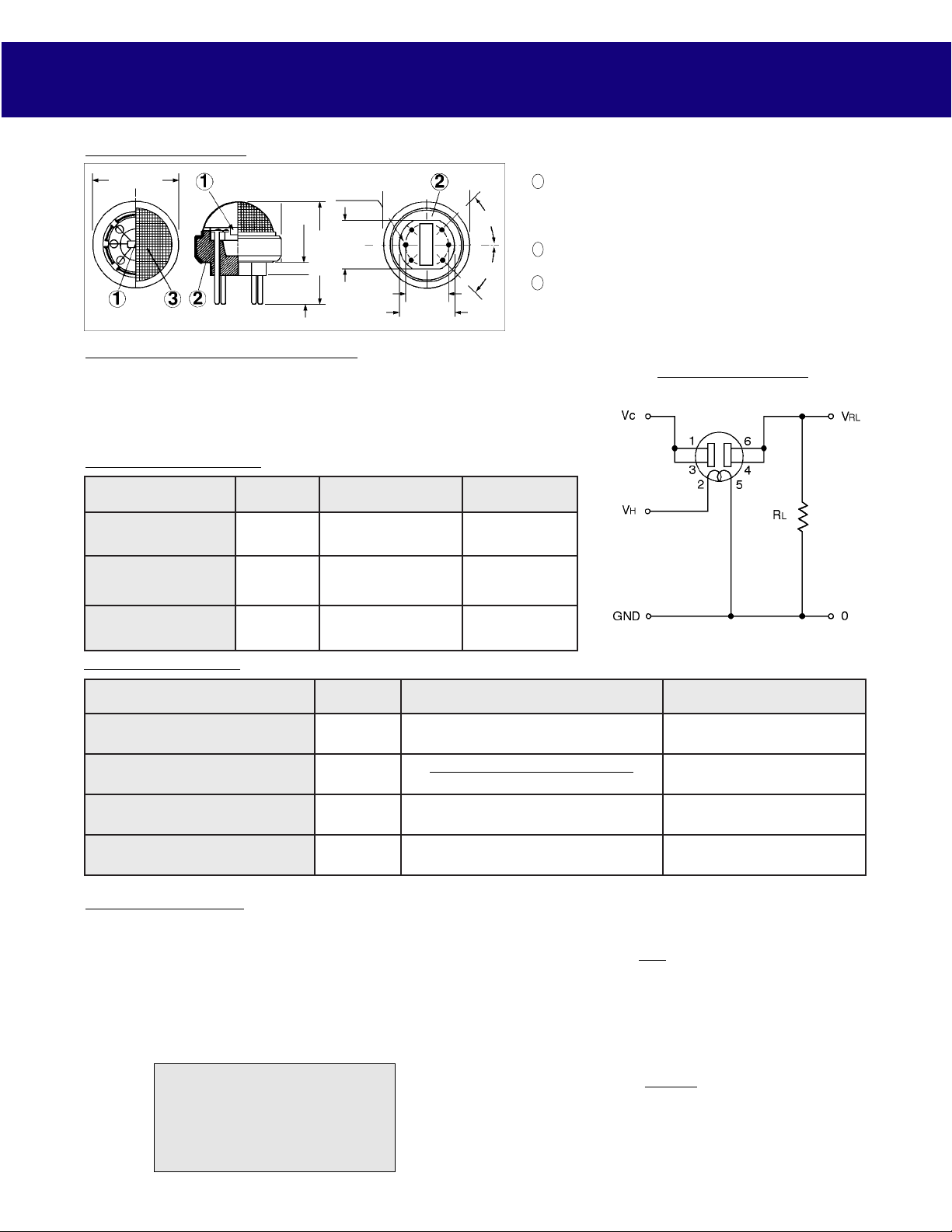
Structure and Dimensions:
SUNSTAR传感与控制 http://www.sensor-ic.com/ TEL:0755-83376549 FAX:0755-83376182 E-MAIL:szss20@163.com
SUNSTAR自动化 http://www.sensor-ic.com/ TEL: 0755-83376489 FAX:0755-83376182 E-MAIL:szss20@163.com
19.5 ± 0.5
um : mm
3.0 ± 0.2
1.0 ± 0.05
6
11.0 ± 0.2
23.0 ± 1.0
6.5
± 0.2
4
9.5 ± 0.3
13.5
+ 0.3
- 0.2
1
45˚
25
45˚
3
Sensing Element:
1
2 Sensor Base:
3 Flame Arrestor:
Pin Connection and Basic Measuring Circuit:
The numbers shown around the sensor symbol in the circuit diagram at the right
correspond with the pin numbers shown in the sensor's structure drawing (
above
When the sensor is connected as shown in the basic circuit, output across the Load
Resistor (VRL) increases as the sensor's resistance (Rs) decreases, depending on
gas concentration.
Standard Circuit Conditions:
metI lobmyS seulaVdetaR skrameR
egatloVretaeH VH 0.5 ± V2.0CDroCA
egatloVtiucriC VC V42.xaM
ecnatsiseRdaoL RL elbairaVSP*≤Wm51
CDroCA
SP*≤Wm51
SnO2 is sintered to form a thick film on
the surface of an alumina ceramic tube
which contains an internal heater.
Alumina ceramic
100 mesh SUS 316 double gauze
Basic Measuring Circuit:
).
Electrical Characteristics:
metI lobmyS noitidnoC noitacificepS
ecnatsiseRrosneS sRa431-Rta01/mpp0ari4kΩ4~0kΩ
fooitaRegnahC
ecnatsiseRrosneS
ecnatsiseRretaeH R
noitpmusnoCrewoPretaeHP
oR/sR
H
H
Standard Test Conditions:
TGS 832 complies with the above electrical characteristics
when the sensor is tested in standard conditions as specified
below:
Test Gas Conditions: 20°±2°C, 65±5%R.H.
Circuit Conditions: VC = 10.0±0.1V (AC or DC),
VH = 5.0±0.05V (AC or DC),
RL = 10.0kΩ±1%
Preheating period before testing: More than 7 days
FIGARO USA, INC.
3703 West Lake Ave. Suite 203
Wilmette, Illinois 60091
Phone: (847)-832-1701
Fax: (847)-832-1705
email: figarousa@figarosensor.com
REV: 8/92
)ria/mpp003taa431-R(sR
)ria/mpp001taa431-R(sR
5.056.0~0
erutarepmetmooR0.03±0.3Ω
V
H
V0.5=538±09Wm
Sensor Resistance (Rs) is calculated by
the following formula:
Rs = ( -1) x R
VC
VRL
L
Power dissipation across sensor electrodes (Ps)
is calculated by the following formula:
2
VC x Rs
Ps =
2
(Rs + RL)

TGS 传感器通用资料下载
SUNSTAR传感与控制 http://www.sensor-ic.com/ TEL:0755-83376549 FAX:0755-83376182 E-MAIL:szss20@163.com
SUNSTAR自动化 http://www.sensor-ic.com/ TEL: 0755-83376489 FAX:0755-83376182 E-MAIL:szss20@163.com
半导体气体传感器(品牌:日本 Figaro)
型号 测量气体 量程(ppm) 灵敏度(电阻比) 典型应用
空气清新
TGS2600-B00
香烟气,氢气,酒精,甲烷,CO 1~30 0.3~0.6
机,换气空
调
TGS2602-B00
TGS2100
TGS2104
TGS2201
TGS813
TGS816
TGS2610-BOO
TGS2610-J00
TGS2611-B00
TGS2611-C00
TGS821
甲苯,乙醇,H2S,NH3,H2等1~30 0.15~0.5
油烟气,氢气,燃气 1~30 0.2~0.6
汽油机尾气(H2,CO,HC) 10~1000 0.3~0.6
汽油/柴油机尾气(NO,NO2)
10~100/0.1~
10
易燃气体(甲、丙、丁烷) 500~10,000
易燃气体(甲、丙、丁烷) 500~10,000
易燃气体(丁烷)<圆型,酒精过滤> 500~10,000
易燃气体(丁烷)<方型> 500~10,000
天然气(甲烷)<圆型,酒精过滤> 500~10,000
天然气(甲烷)<圆型>
氢气
500~10,001
30~1000 0.6~1.20
0.35/2.5
0.60±0.05
0.60±0.05
0.53±0.05
0.53±0.05
0.60±0.06
0.60±0.06
空气清新
监测仪
抽油烟机,
空气清新
机
汽车尾气
检测
家庭燃气
泄漏报警
器
工业用易
燃, 易爆
民用/工业
用易燃,易
爆
民用/工业
用易燃,易
爆
气体探测
气,报警器
气体探测
气,报警器
TGS2442
T GS2620-A00
TGS2620-C00
TGS822
TGS825
TGS826
一氧化碳 30~1,000
酒精(金属外壳) 50~5,000
酒精(不锈钢外壳)
50~5,000
酒精 50~5,000
硫化氢 5~100 0.3~0.6
氨气 30~300 0.4~0.70 电冰箱气
0.23~0.49
0.35±0.1
0.35±0.1
0.40±0.1
室内气体
报警器
酒精探测
器
酒精探测
器
醉酒度测
试仪
有毒有害
气体报警
器

TGS830 R-113,R-22,R-11,R-12
SUNSTAR传感与控制 http://www.sensor-ic.com/ TEL:0755-83376549 FAX:0755-83376182 E-MAIL:szss20@163.com
SUNSTAR自动化 http://www.sensor-ic.com/ TEL: 0755-83376489 FAX:0755-83376182 E-MAIL:szss20@163.com
TGS831 R-21,R-22
TGS832 R-134a
KE-25
KE-50
KE-25F3
TGS4160
TGS4161
AM-4
AM-4-4161
COM2442
LPM2610
NGM2611
AMS2600
AMS2100
AM-1-2600
氧气(电化学式,5 年寿命) 0~100%
氧气(电化学式,10 年寿命) 0~100%
氧气(电化学式,5 年寿命) 0~100%
二氧化碳(固态,10 年寿命)
二氧化碳(固态,10 年寿命)
二氧化碳模块,用于检测
TGS4160,重新标定 TGS4160
二氧化碳模块,用于检测
TGS4161,重新标定 TGS4161
一氧化碳检测模块,设置 30、70、
150ppm 三档报警
TGS2610 检测模块,可以用于居
民区液化石油气泄露报警
TGS2611 检测模块,可以用于居
民区天然气泄露报警
TGS2600 检测模块,可以用于空
调、空气清新机等家电
TGS2100 检测模块,可以用于智
能抽油烟机等厨房电器
TGS2600 检测模块,检测低浓度
的空气污染物(带微处理器)
日本 FIGARO
体探测
100~3,000
100~3,000
0.30±0.10
0.40±0.15
100~3,000 0.50~0.65
±1%
±2%
±1%
350~30000ppm ±20%@1000ppm
350~5000ppm ±20%@1000ppm
500~10000ppm
500~10000ppm
1~30ppm
(小尺寸,低功耗) CO2检测
卤素检漏
仪,
氟利昂检
测器
氧气分析
仪
氧气分析
仪
氧气分析
仪
蔬菜大棚,
孵化设备
蔬菜大棚,
孵化设备
CO2 检测
TGS 8 系列传感器 8-Series TGS Sensor
产品/型号 产品样图 用途 主要检测对象 检测范围 使用电压 消耗功率 特徴 详细
可燃气体泄漏
甲烷、丙烷
TGS813
可燃气体检测
500~10,000ppm DC5V 835mW
报警器应用
异丁烷
30 年业绩

有机溶剂、
SUNSTAR传感与控制 http://www.sensor-ic.com/ TEL:0755-83376549 FAX:0755-83376182 E-MAIL:szss20@163.com
SUNSTAR自动化 http://www.sensor-ic.com/ TEL: 0755-83376489 FAX:0755-83376182 E-MAIL:szss20@163.com
TGS822
TGS822TF
TGS203S
有机溶剂检测 酒精有机溶剂 50~5,000ppm DC5V 660mW
煤制气检测 煤制气中氢气 200~5,000ppm DC5V 660mW
不完全燃烧
一氧化碳 50~1,000ppm H/L 驱动
气体检测
295/33mW
(ave.138mW)
酒精检测报警器
应用 20 年业绩
煤制气泄漏报警器
应用 10 年业绩
防一氧化碳中毒
报警器应用
20 年业绩
TGS2000 系列气体传感器 TGS2000-Series Gas Sensor
产品/型号 产品样图 用途 主要检测对象 检测范围 使用电压 消耗功率 特徴 详细
TGS2600
空气质量控制 香烟酒精 1~10ppm DC5V 210mW
空气清新机应用业
绩 空气质量控制器
TGS2602
空气质量控制 酒精氨气 VOC 1~10ppm DC5V 280mW
空气清新机应用业
绩 空气质量控制器
石油液化气泄漏报
TGS2610
TGS2611
可燃气体检测 丙烷异丁烷 500~10,000ppm DC5V 280mW
可燃气体检测 甲烷天然气 500~10,000ppm DC5V 280mW
警器应用业绩低功
耗
天然气泄漏报警器
应用业绩低功耗
TGS2620
有机溶剂检测 酒精有机溶剂 50~5,000ppm DC5V 210mW
有机溶剂检测方面
业绩低功耗
一氧化碳报警器应
TGS2442
产品型号 产品样图 用途 主要检测气体 检测浓度范围 工作电压 功率 详细
毒性气体检测 一氧化碳 30~1,000ppm DC5V 脉冲 驱动 14mW(ave.)
用业绩低功耗平均
約 14mW
TGS203S
SUNSTAR传感与控制 http://www.sensor-ic.com/ TEL:0755-83376549 FAX:0755-83376182 E-MAIL:szss20@163.com
SUNSTAR自动化 http://www.sensor-ic.com/ TEL: 0755-83376489 FAX:0755-83376182 E-MAIL:szss20@163.com
TGS813
TGS2610
毒性气体检测
可燃性气体
可燃性气体
一氧化碳
甲烷
丙烷
丁烷
丙烷
丁烷
50~1000ppm H/L 驱动
500~10000ppm
500~10000ppm
DC5V 835mW
DC5V 280mW
295/33mW
详细
详细
详细
TGS2611
TGS2620
TGS822
TGS822TF
TGS2600
TGS2602
可燃性气体
溶剂蒸气
溶剂蒸气
可燃性气体
空气质量控制
空气质量控制
甲烷
酒精
有机溶剂
酒精
有机溶剂
人工煤制气中
氢气
氢气
酒精
酒精
氨气
有机溶剂
挥发
500~10000ppm
50~5000ppm
50~5000ppm
DC5V 280mW
DC5V 280mW
DC5V 660mW
200~5000ppm DC5V 660mW
1~10ppm DC5V 210mW
1~10ppm DC5V 280mW
详细
详细
详细
详细
详细
详细
TGS821
TGS825
TGS826
TGS830
由【日本费加罗技研株式会社】
生产
TGS2442
TGS3870
TGS4160
氢气
硫化氢
氨气 胺
氟利昂 有机氯气
一氧化碳
甲烷 一氧化碳(复
合型)
详细
 Loading...