

Page 1

APPLICATION NOTES FOR TGS2611
Application Notes for Methane Gas Detectors using TGS2611
The TGS2611 methane gas sensor
has been presorted into
groupings which will allow users
to simplify the manufacturing
process for methane gas
detectors. This brochure offers
example application circuits and
important technical advice for
designing and manufacturing gas
detectors which use classified
TGS2611 sensors.
Page
an ISO9001 company
Introduction......................................................................................................2
Detector Circuit Design
Basic Circuit with T emperature Compensation............................................2
Selecting a Load Resistor .................................................................................2
Compensation for Internally Generated Heat..............................................3
Heater Breakage Detection Circuit.........................................................3
Sensor Malfunction Detection Circuit.........................................................3
Prevention of Intermittent Alarming..............................................................4
Alarm Prevention during W armup................................................................4
Alarm Delay Circuit..........................................................................5
Application Circuit...................................................................................5
Manufacturing Process
Handling and Storage of Sensors..........................................................5
L Selection...............................................................................................5
R
PCB Assembly....................................................................................5
Sensor Assembly..................................................................................5
Final Assembly.................................................................................................6
Preheating of Final Assembly.....................................................................6
Gas Test..............................................................................................6
Storage of Finished Products..........................................................................6
Anticipated Performance at 10%LEL of Methane...........................................................6
Pre-calibrated Sensor Module...........................................................................................7
Appendix...............................................................................................................8
See also Technical Brochure ‘Technical Information on Usage of TGS
Sensors for Toxic and Explosive Gas Leak Detectors’.
Revised 08/03
IMPORTANT NOTE: OPERATING CONDITIONS IN WHICH FIGARO SENSORS ARE USED
WILL VARY WITH EACH CUSTOMER’S SPECIFIC APPLICATIONS. FIGARO STRONGLY
RECOMMENDS CONSULTING OUR TECHNICAL STAFF BEFORE DEPLOYING FIGARO
SENSORS IN YOUR APPLICATION AND, IN PARTICULAR, WHEN CUSTOMER’S TARGET
GASES ARE NOT LISTED HEREIN. FIGARO CANNOT ASSUME ANY RESPONSIBILITY
FOR ANY USE OF ITS SENSORS IN A PRODUCT OR APPLICATION FOR WHICH SENSOR
HAS NOT BEEN SPECIFICALLY TESTED BY FIGARO.
TGS2611-J00 is a UL recognized component in accordance with the
requirements of UL2075. Please note that component recognition testing
has confirmed long term stability in 60ppm of methane; other characteristics
shown in this brochure have not been confirmed by UL as part of component
recognition.
1
Page 2
APPLICATION NOTES FOR TGS2611
To facilitate ease in manufacturing gas detectors,
both Figaro TGS2611-J00 and TGS2611-B00
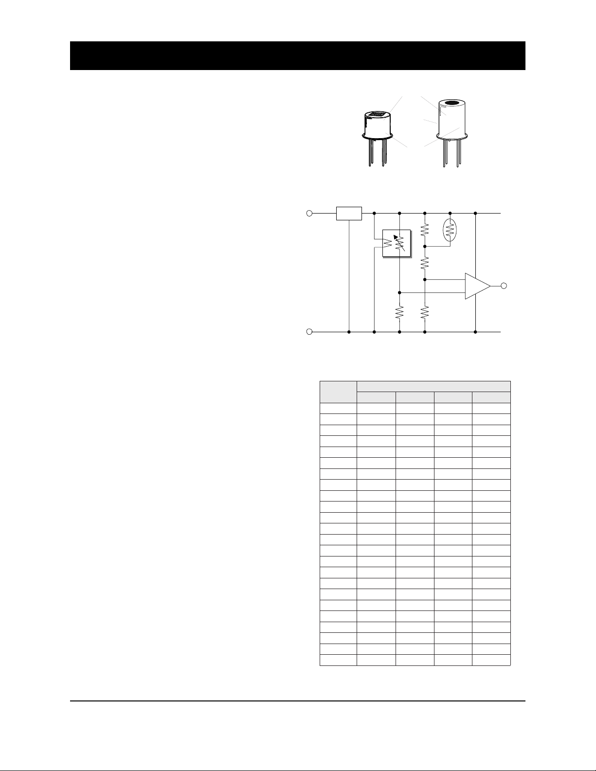
methane gas sensors are individually marked with
an ID number (see Figure 1) indicating a factory
presorted classification which corresponds to
narrow ranges of sensor resistance in methane.
When the sensor’s ID number is properly used,
the calibration process can be greatly simplified,
eliminating long preconditioning time and the
complicated handling of calibration gas.
1. Detector Circuit Design
1-1 Basic circuit with temperature compensation
Figure 2 shows an example of a basic circuit for
gas detection, including temperature compensation for variations caused by ambient
temperature fluctuations. Typical values for the
circuit components are as follows:
RL : refer to Table 1
R
TH : 4.7k
Ω (±
3%), B=3977 (±5%)
RA : 11.5kΩ (±1%)
RB : 4.32kΩ (±1%)
RC : 8.25kΩ (±1%)
The values for components related to
temperature compensation should be chosen so
that Vref is one-half of the Vc value at standard
temperature (20˚C). The Vref curve should
approximate the temperature dependency curve
of the VRL when compensation is properly done.
1-2 Selecting a load resistor (R
L)
To optimize resolution of the output signal at
the desired alarming concentration, it is necessary to adjust the resistance of the load resistor
(RL). It is recommended that RL be selected at a
value which is equal to the sensor’s resistance
(Rs) at the alarming concentration (i.e. Rs/RL =
1.0). Please refer to the brochure “General
Information for TGS Sensors” for more details.
Since the ID number corresponding to sensor
resistance in methane gas is indicated on the
sensor cap, the load resistor value can be selected
according to Table 1. For example, for an alarm
setting at 10% LEL, when using a sensor having
an ID number of 7, the R
L value should be set at
1.27kΩ. By using the recommended RL, the VRL
value at the alarming point typically will be 2.5V,
which is equal to half of the circuit voltage (Vc).
Sensor
code
TGS2611
984AA
TGS2611-J00 TGS2611-B00
Fig. 1 - Sensor markings
Voltage
regulator
78M05
D.C. input
#DI
10679.0517.0095.0115.0
2070.1787.0946.0265.0
3081.1668.0517.0916.0
4003.1359.0787.0186.0
5034.150.1668.0057.0
6085.151.1359.0528.0
7047.172.150.1909.0
8019.104.151.100.1
9001.245.172.101.1
0123.296.104.112.1
1155.278.145.133.1
2108.250.296.174.1
3190.362.278.126.1
4104.394.250.287.1
5147.347.262.269.1
6121.410.394.251.2
7135.423.347.273.2
8199.456.310.316.2
9194.520.423.378.2
0240.624.456.361.3
1256.678.420.484.3
2223.763.524.438.3
3260.809.578.422.4
4278.894.663.546.4
Note: Lower explosion limit (LEL) of methane = 50,000ppm
Vc = 5.0 ± 0.2V
4
1
Fig. 2 - Basic circuit with
temperature compensation
rosneS
Table 1 - Recommended RL by sensor ID
Lot #
#07
ID #
3
2
TGS
2611
R
L
RLk( Ω htiw) ± ecnarelot%1
LEL%5 LEL%01 LEL%51 LEL%02
A
R
B
R
C
R
TGS2611
314AE #07
REF
V
RL
V
TH
R
+
-
Alarm signal
(Active = 'L')
Comparator
GND
Revised 08/03
2
Page 3
APPLICATION NOTES FOR TGS2611
)
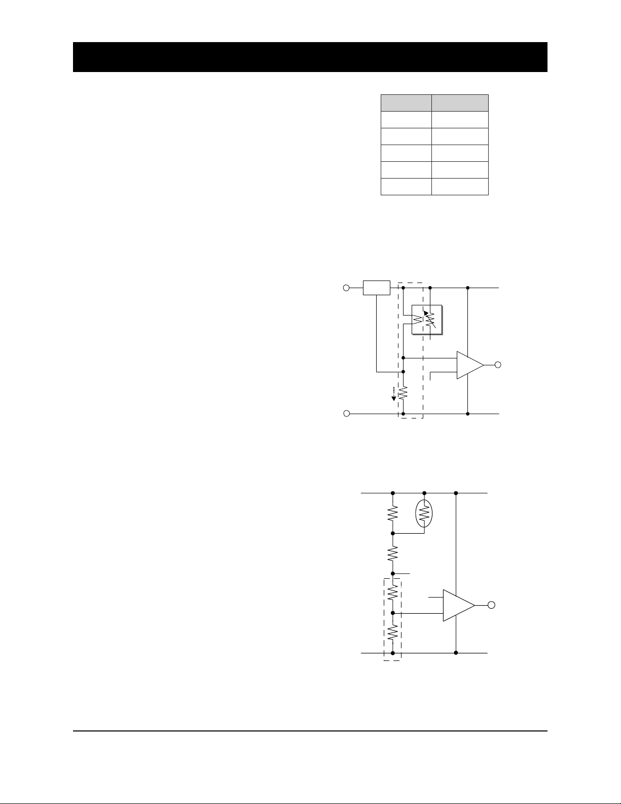
1-3 Compensation for internally generated heat
Depending on the design of the case and the
PCB, there is often a difference between the
temperature near the thermistor’s placement in
the detector and the ambient temperature.
Therefore it is recommended to measure the
actual temperature difference between the inside
and the outside of the detector and select the
value of RC according to Table 2. When RC is
selected in this manner and used in the basic
circuit (Figure 2), the result would be that
Vref=1/2 Vc.
1-4 Heater breakage detection circuit
Figure 3 shows an example of how breakage of
the sensor’s heater wire and/or heater element
can be detected. By adding R
E (3.57Ω±1%) into
the circuit and monitoring VRE, a malfunction
can be considered to have occurred when VRE
(0.2V typ.) drops to near 0V. Please note that a
circuit voltage (Vc) of 5.2V should be applied to
a circuit which incorporates a heater malfunction
detection circuit.
∆∆∆∆∆ )C˚(T
k(cR Ω)
052.8
586.7
0151.7
5156.6
0243.6
∆
T= (temp near themistor)-(temp outside detector)
Table 2 - Effect on selection of Rc by temperature
differential inside and outside of detector
Vc=5.2V
78M05
Heater breakage
signal
(Active = 'L')
GND
56mA (typ.)
R
0.05~0.1V
E
0.2V (typ.
+
-
1-5 Sensor malfunction detection circuit
Breakage of lead wires to the sensor’s electrodes
and/or sensor element can be detected by using
a circuit such as that shown in Figure 4. This
involves replacing R
C with RC1 and RC2, selecting
their values so that RC1/RC2≈35. Since VRL is
normally greater than 70mV in any atmospheric
conditions, by comparing VRL to a reference
voltage of 70mV, breakage of the lead wires and/
or sensor element can be considered to have
occurred if VRL drops below 70mV.
Figure 3 - Heater breakage detection circuit
C
V
C1
R
C2
R
Figure 4 - Sensor malfunction detection circuit
(RE = 3.57Ω±1%)
A
R
B
R
70mV (typ.)
TH
R
REF
V
+
RL
V
(RC1/RC2 ≈ 35)
-
Sensor breakage
signal
(Active = 'L')
GND
Revised 08/03
3
Page 4
APPLICATION NOTES FOR TGS2611
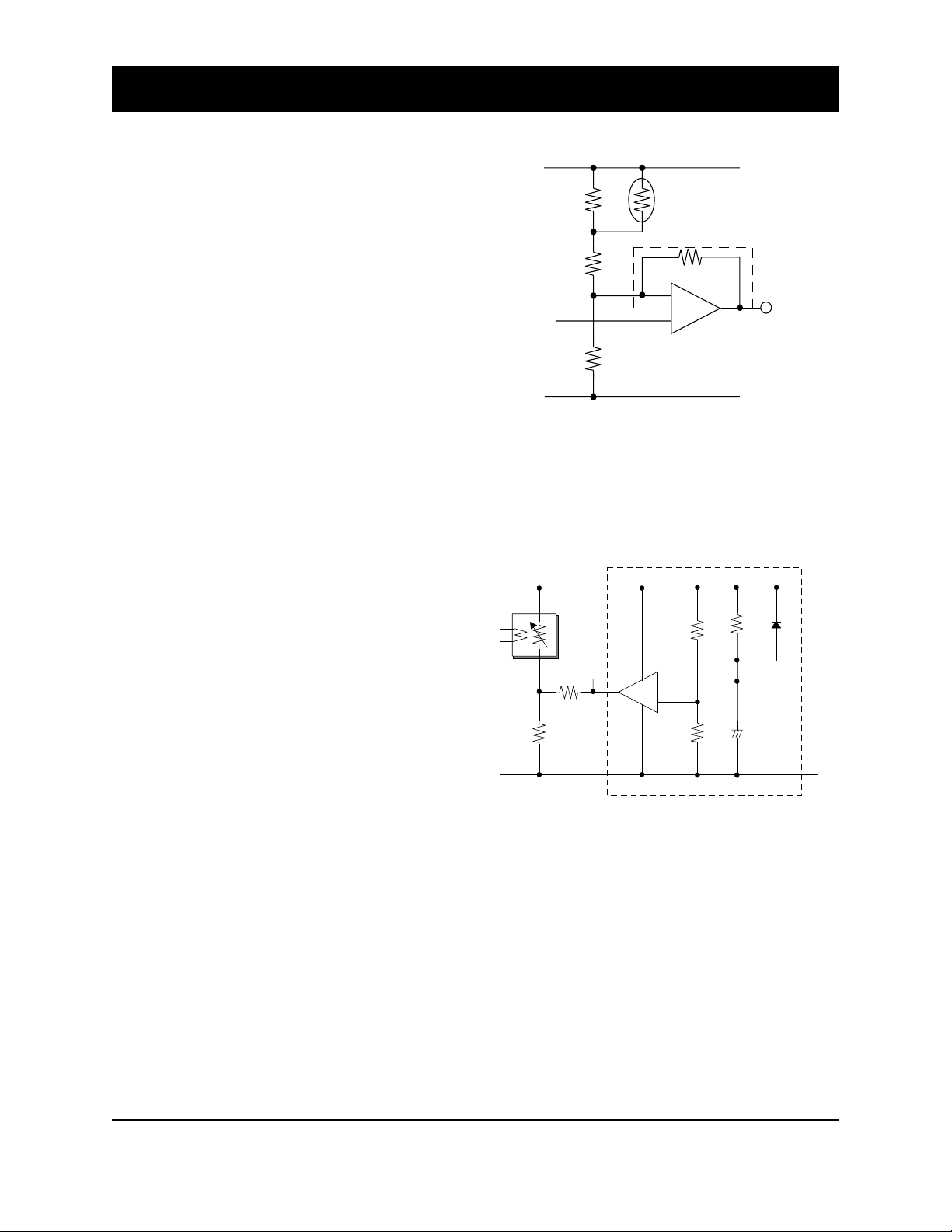
1-6 Prevention of intermittent alarming
When gas concentration fluctuates right at the
alarming threshold, dropping just below and
rising just above, the detector would
intermittently alarm in short bursts. In order to
prevent the nuisance of intermittent alarming,
a circuit such as that shown in Figure 5 can be
used. By adding RD to the original circuit, a
Schmidt trigger circuit which includes a
comparator can be created (the value of RD
should be set at 20-30 times that of Rc). As a
result, a range for the alarming threshold is
created. An alarm is then generated when the
upper range of the threshold is breached and
the alarm signal would cease after the signal
drops below the lower end of the threshold
range, thus eliminating frequent intermittent
alarming.
1-7 Alarm prevention during warm-up
As described in Sec. 2-6 of “Technical Information
for TGS2611”, when energizing the sensor after
an unpowered period, the sensor’s resistance
(Rs) drops sharply for the first few seconds after
energizing, regardless of the presence of gases,
before recovering to a stable level. This ‘initial
action’ may cause activation of an alarm during
the first few moments of energizing since V
RL
would exceed Vref. To prevent this from
happening, a circuit modification such as that
shown in Figure 6 may be used. After powering
the detector, sensor output (VRL) should be set
to zero for a pre-determined period (2.5 minutes
is recommended--the timer function should be
created by selecting the proper combination of
C3 and R11). In order to restrict current to the
sensor during this period, the recommended
value of RF should exceed 5kΩ.
C
V
A
R
B
R
REF
V
RL
V
C
R
Figure 5 - Circuit for prevention of intermittent alarming
C
V
RL
V
F
R
R
L
Figure 6 - Circuit for alarm prevention during warmup
R
TH
D
R
+
-
(RD/RC = 20~30)
2.5 min. time delay circuit
+
-
(RF > 5kΩ)
R
9
R
10
Alarm signal
(Active = 'L')
GND
R
+
C
11
3
D
5
GND
Revised 08/03
4
Page 5
APPLICATION NOTES FOR TGS2611
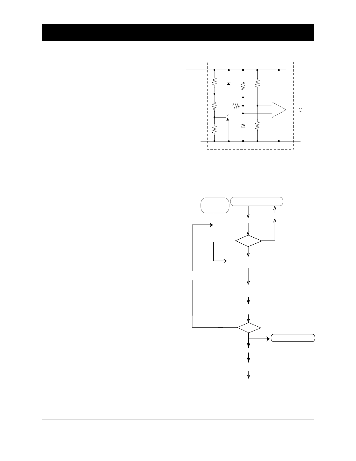
1-8 Alarm delay circuit
To prevent false alarms caused by transient
interference gases such as alcohol in cooking
vapors, a delay circuit modification such as that
shown in Figure 7 can be used. The alarm signal
generated by this circuit should be connected to
the comparator in the basic circuit (see Figure
1). The recommended timer period for alarm
delay is 15 seconds--the timer function should
be created by selecting the proper combination
of C4 and R15.
1-9 Application circuit
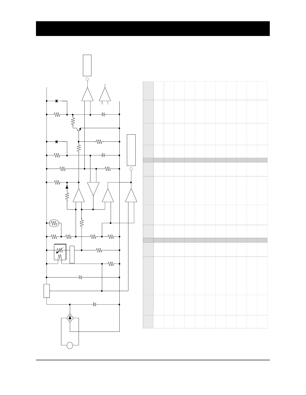
An application circuit which incorporates all of
the advice included in Secs. 1-1 through 1-8 can
be seen in Appendix 1.
2. Manufacturing Process (see Fig. 8)
2-1 Handling and storage of sensors
Prior to usage, sensors should be stored at room
temperature in a sealed bag containing normal
clean air. During manufacturing, sensors should
be handled in a clean air environment and at
room temperature. Clean air refers to air free of
contaminants, excessive dust, solvent vapors,
etc. Room temperature should be 20~25˚C.
2-2 R
L selection
Choose the proper resistor for RL by referring to
the ID number of the sensor and Table 1.
2-3 PCB assembly
Flux should be sufficiently dried before sensors
are assembled onto the PCB to avoid any
contamination of the sensor by flux vapors.
C
V
Alarm signal
(Active = 'L')
Investigation
15 sec. time delay circuit
8
R
D
6
R
12
R
14
Tr
+
R
13
Figure 7 - Alarm delay circuit
Acceptance of
classified sensor
RL selection
Acceptance of components
PCB Assembly
PCB Test
Sensor and RL Assembly
(manual soldering)
Final Assembly
(PCB, casing etc.)
Preheating
(≥48 hours)
R
9
R
15
Delayed alarm
3
signal
(Active = 'L')
GND
IC
+
-
C
4
R
10
Repair
*3
NG
OK
2-4 Sensor assembly
Manual soldering of the sensor to the PCB is
strongly advised. Solders composed of
Sn63:Pb37 or Sn60:Pb40 with non-chloric resin
flux (MIL: RMA Grade; for example, Almit KR-
19) are recommended for usage.
2-5 Final assembly
Avoid any shock or vibration which may be
caused by air driven tools. This may cause
breakage of the sensor’s lead wires or other
physical damage to the sensor.
Revised 08/03
NG
Figure 8 - Manufacturing process flowchart
Gas Test
OK
Packing
Storage
Shipping
Quality control sampling
*Alarm concentration
*Long term stability
5
Page 6
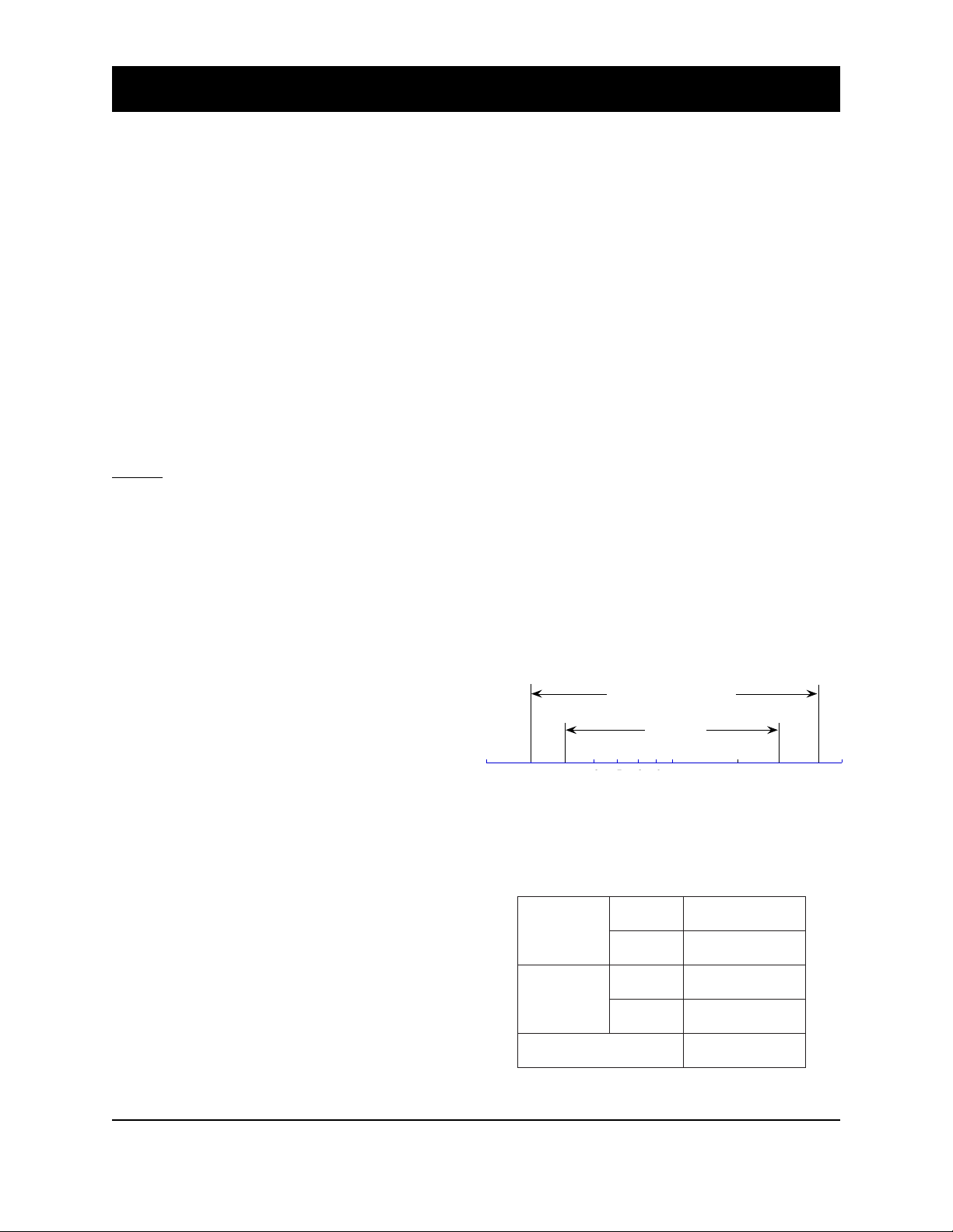
2-6 Preheating of final assembly
345678910 2015 30
under std
test conditions
under operating conditions
at recommended circuit condition
Alarming point (%LEL)
25
To stabilize the detector assembly before gas
testing, the minimum period for preheating final
assemblies should be 48 hours at room
temperature (20~25˚C). Be certain to maintain
clean atmospheric conditions for preheating.
2-7 Gas test
Test all finished products in the target gas under
normal operating conditions. Keep the
atmospheric conditions in the chamber stable,
utilizing a user-defined standard test condition
which is based on applicable performance
standards and on anticipated usage for
detectors. Remove any traces of smoke,
adhesives, gases, or solvents from the chamber.
NOTE: Without testing after final assembly,
detectors have no guarantee of accuracy or
reliability.
APPLICATION NOTES FOR TGS2611
2-8 Storage of finished products
Detectors should be stored in a clean air environment at room temperature. Avoid storage in
dirty or contaminated environments. Cautions
listed in Sec. 6-1.3 of “General Information for
TGS Sensors” should also be observed.
3. Anticipated Performance at 10%LEL of
Methane
When using the classified TGS2611 with Figaro’s
recommended R
L for 10%LEL (Table 1) and
temperature compensated circuit design (Figure
2), typical alarm tolerances for 10%LEL of
methane such as those shown in Figure 9 are
expected. Each RL classification contains a range
of tolerance as exemplified by the alarming
range labelled as ‘standard conditions’ (i.e. these
conditions are well-controlled). When factoring
in the additional effects of environmental
extremes and the allowable variation in circuit
conditions, the resulting alarming range would
be typified by the range labelled as ‘operating
conditions’. However, in actual usage, alarm
thresholds may vary since the threshold is also
affected by factors such as the tolerances of the
thermistor and/or other components, load
resistor value, test conditions, and heat
generation inside the detector enclosure. As a
Revised 08/03
Figure 9 - Expected performance of methane detectors
with classified TGS2611 & recommended RL for 10% LEL
performance of methane detectors as shown in Figure 9
(refer to Table 3 for test conditions)
dradnatS
dnaerutarepmeT
ytidimuh
dradnatS
tiucriC
noitidnoc
roirpgninoitidnoC
tsetot
Table 3 - Test conditions for measuring
02 ± 56,C˚2 ± HR%5
snoitidnoc
gnitarepO
snoitidnoc
snoitidnoc
gnitarepO
snoitidnoc
0.5=cV ± CDV10.0
0.5=HV ± CDV50.0
0.5=cV ± CDV2.0
0.5=HV ± CDV2.0
≥ sruoh84
HR%59~03,C˚04~01-
6
Page 7
result, Figaro neither expressly nor impliedly
warrants the performance shown in Figure 9. If
a large difference between the expected and
actual performance of detectors is noticed, please
consult with Figaro.
Pre-calibrated sensor module
Figaro has available a pre-calibrated methane
sensor module NGM2611 (see Fig. 10). This
module includes the classified TGS2611 sensor,
a matched load resistor, and a factory preset
temperature compensation circuit, all on a small
PC board. The NGM2611 module is calibrated
for a typical set point at 10% LEL, achieving
performance as indicated in Figure 9 by simply
plugging it into a main PC board. Please refer
to the brochure “Product Information for
NGM2611” for detailed information.
APPLICATION NOTES FOR TGS2611
Figure 10 - Pre-calibrated sensor module NGM2611
Important Reminder
Without testing alarm threshold after final assembly,
detectors have no accuracy or reliability guarantee.
Figaro USA Inc. and the manufacturer, Figaro
Engineering Inc. (together referred to as Figaro)
reserve the right to make changes without notice to
any products herein to improve reliability,
functioning or design. Information contained in this
document is believed to be reliable. However, Figaro
does not assume any liability arising out of the
application or use of any product or circuit described
herein; neither does it convey any license under its
patent rights, nor the rights of others.
FIGARO GROUP
HEAD OFFICE
Figaro Engineering Inc.
1-5-11 Senba-nishi
Mino, Osaka 562-8505 JAPAN
Tel.: (81) 72-728-2561
Fax: (81) 72-728-0467
email: [email protected]
OVERSEAS
Figaro USA Inc.
3703 West Lake Ave. Suite 203
Glenview, IL 60025-1266 USA
Tel.: (1) 847-832-1701
Fax.: (1) 847-832-1705
email: [email protected]
Figaro's products are not authorized for use as critical
components in life support applications wherein a
failure or malfunction of the products may result in
injury or threat to life.
Revised 08/03
7
Page 8
APPLICATION NOTES FOR TGS2611
IC
1
R
L
R
1
SENSOR
Alarm signal
(Active "L")
Power Supply
(AC10V / 80mA)
++-
-
+-+
C
3
D
6
Tr
IC
2
1/4
2/4
1/2
+
-
3/4
+
-
4/4
Malfunction signal
(Active "L")
+
+
+
R2R
3
R
9
R
5
R
6
R
8
R7R
4
R
10
R
11
R
12
R
15RTH
D
7
C4C
2C1
IC
3
+
-
2/2
~
D
1~4
R
13
R
14
1
4
3
2
(Note: "L" output also occurs during initial delay)
Initial delay: approx. 2.5 minutes
Alarm delay: approx. 15 seconds
D
5
traP
.oN
emantraP
/.oNledoM
noitacificepS
rekaM
traP
.oN
emantraP
/.oNledoM
noitacificepS
rekaM
traP
.oN
emantraP
/.oNledoM
noitacificepS
rekaM
rosneSrosnessaG1162SGToragiF
R
9
rotsiseRk01ΩW8/1%5,
D
1
noitacifitceR
edoid
G6655SabihsoT
R
HT
CTN
rotsimreht
k7.4Ω7793=B,spillihP
R
01
rotsiseRk01ΩW8/1%5,
D
2
noitacifitceR
edoid
G6655SabihsoT
R
L
rotsiseRW8/1,%1,)1elbaTeeS(
R
11
rotsiseRk074ΩW8/1%5,
D
3
noitacifitceR
edoid
G6655SabihsoT
R
1
rotsiseR75.3ΩW2/1,%1,
R
21
rotsiseRk01ΩW8/1%5,
D
4
noitacifitceR
edoid
G6655SabihsoT
R
2
rotsiseRk5.11ΩW8/1,%1,
R
31
rotsiseRk01ΩW8/1%5,
D
5
langisllamS
edoid
8851S1abihsoT
R
3
rotsiseRk23.4ΩW8/1,%1,
R
41
rotsiseRk1ΩW8/1%5,
D
6
langisllamS
edoid
8851S1abihsoT
R
4
rotsiseRk78.7ΩW8/1%1,
R
51
rotsiseRk074ΩW8/1%5,
D
7
langisllamS
edoid
8851S1abihsoT
R
5
rotsiseR622ΩW8/1%1,
C
1
citylortcelE
roticapac
074µV52/F
rT
NPN
rotsisnart
3062CS2ihsibustiM
R
6
rotsiseRk01ΩW8/1%5,
C
2
citylortcelE
roticapac
01µV01/F
CI
1
egatloV
rotaluger
TC50M87CMalorotoM
R
7
rotsiseRk002ΩW8/1%5,
C
3
citylortcelE
roticapac
074µ%01,V01/F
CI
2
rotarapmoC933MLalorotoM
R
8
rotsiseRk01ΩW8/1%5,
C
4
citylortcelE
roticapac
74µ%01,V01/F
CI
3
rotarapmoC393MLalorotoM
Appendix 1 - Example application circuit for gas detector using classified TGS2611
Revised 08/03
8
 Loading...