

Fife Corporation
PO Box 26508, Oklahoma City, OK 73126, U.S.A.
Phone: 405.755.1600 / Fax: 405.755.8425
www.fife.com / E-mail: fife@fife.com
SBPC-21-PB
FifeNet to Profibus™ Gateway
Customer Instruction Manual
PROFIBUS DP
© 2002 Fife Corporation. All rights reserved.


SBPC-21-PB CUSTOMER INSTRUCTION MANUAL
COPYRIGHT
• • • • • •
All rights reserved. Any reproduction of this Instruction Manual, in any form, in whole or in part,
requires the prior written consent of Fife Corporation.
The information given in this Instruction Manual is subject to change without notice.
We have compiled this Instruction Manual with the greatest possible care and attention. However, the
possibility of error cannot be completely excluded. Fife Corporation accepts no legal liability for
incorrect information given and the consequences arising therefrom.
AnyBus is a registered trademark of HMS Industrial Networks AB.
All other trademarks are the property of their respective holders.


SBPC-21-PB CUSTOMER INSTRUCTION MANUAL
TABLE OF CONTENTS
• • • • • •
GENERAL INFORMATION ............................................................................................................................1
Introduction ..............................................................................................................................................1
Profibus DP Overview..............................................................................................................................1
Producer/Consumer Model......................................................................................................................3
FifeNet .....................................................................................................................................................3
SBPC-21-PB Switch/Jumper Configuration.............................................................................................4
SBPC-21-PB External Connections/Switches/Indicators.........................................................................5
Profibus DP Baud Rate............................................................................................................................5
SBPC-21-PB Network Status ..................................................................................................................6
SBPC-21-PB Error Codes .......................................................................................................................7
F
IFENET THEORY ......................................................................................................................................9
FifeNet Time Slices..................................................................................................................................9
Multiplexed Time Slices ...........................................................................................................................9
FifeNet Master .......................................................................................................................................10
SBPC-21-PB Data Flow.........................................................................................................................10
C
ONFIGURATIONS....................................................................................................................................13
Hardware Configuration - Single CDP-01..............................................................................................13
Hardware Configuration - Multiple CDP-01’s.........................................................................................14
Software Configuration ..........................................................................................................................14
GSD File ................................................................................................................................................14
C
OMMUNICATION MAPPING......................................................................................................................15
Profibus to FifeNet Data ........................................................................................................................15
FifeNet to Profibus Data ........................................................................................................................16
C
ONTROL INFORMATION ..........................................................................................................................19
CDP-01 Control Matrix...........................................................................................................................19
External Lock .........................................................................................................................................19
Status Data Block ..................................................................................................................................22
PECIAL CONTROL OF FIFENET DEVICES.................................................................................................29
S
CDP-01 Key Code Data Path ................................................................................................................29
CDP-01 Key Codes ...............................................................................................................................30
Simulating Dual-Key Presses ................................................................................................................30
CDP-01 LED Panel Data .......................................................................................................................31
I
NDEX......................................................................................................................................................33

SBPC-21-PB CUSTOMER INSTRUCTION MANUAL
1
GENERAL INFORMATION
• • • • • •
Introduction
The Fife SBPC-21-PB (Serial Bus Protocol Converter) provides a gateway between Fife’s proprietary
FifeNet network and Profibus™. Using the SBPC-21-PB, data originating from FifeNet can be sent on
Profibus and data from Profibus can be sent to FifeNet.
Profibus DP Overview
The supported media for the SBPC-21-PB Profibus is a shielded copper cable consisting of a twisted
pair. The baud rate for the bus is between 9.6K baud to a maximum 12M baud. The Profibus DP
network is able to carry 126 nodes and the total amount of data for Profibus DP is 244 bytes out per
module and 244 bytes in per module. Node 126 is only used for commissioning purposes and should
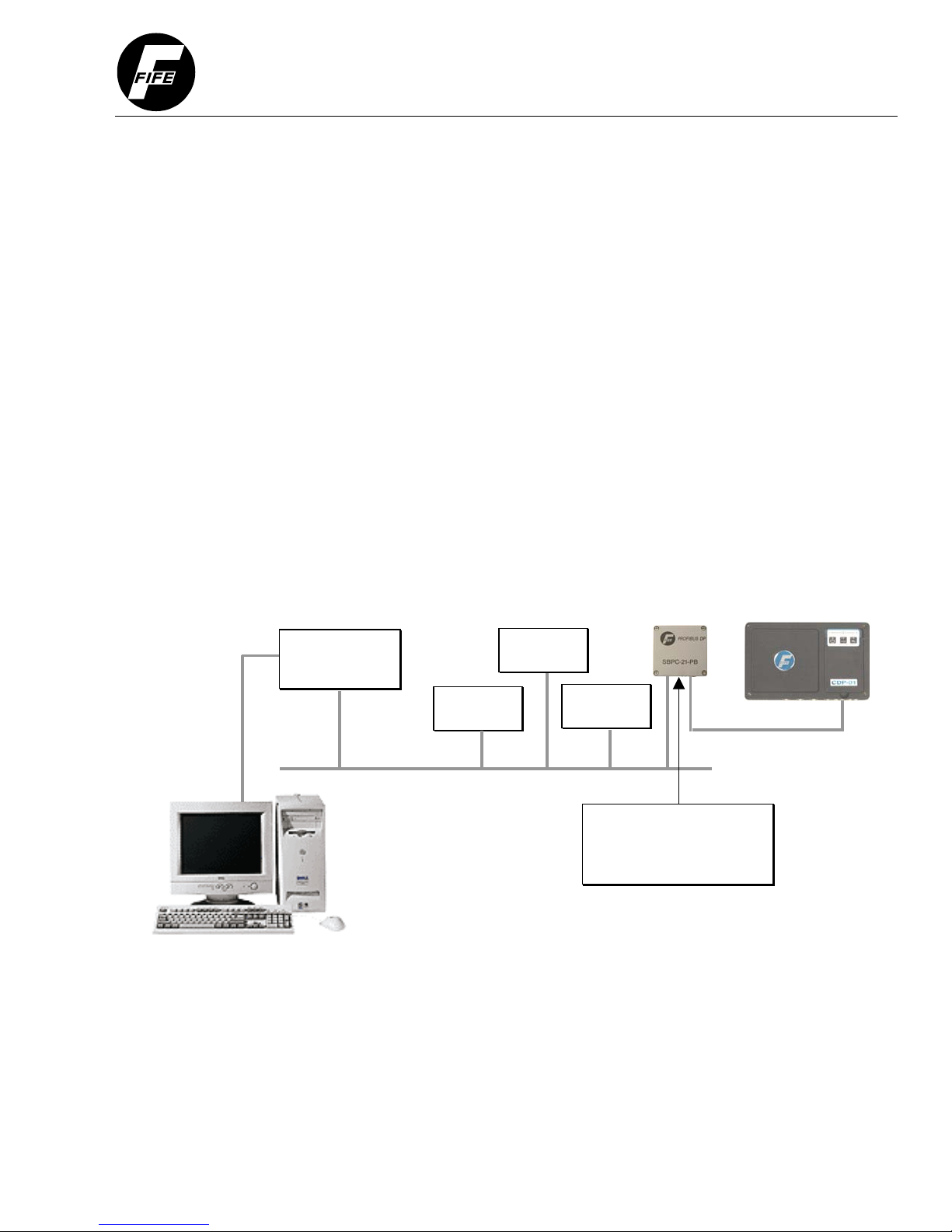
not be used to exchange user data. An example of a Profibus network with an SBPC-21-PB is shown
in the diagram below.
Figure 1-2: Example of an SBPC-21-PB Network Connection
Profibus DP
Master
Profibus DP
Slave #1
Profibus DP
Slave #2
Profibus DP
Slave #3
FifeNet
RS-232
Profibus
The SBPC-21-PB connects
to both FifeNet and Profibus
providing translation between
two networks.
________________________________________________________________________________________________________________
12-20-2002 Figure Sheet 1-851-A Page 1

Table 1-1: Technical Features for Profibus DP
Transmission Technique:
Profibus DIN 19245, Part 1
Medium Access: Hybrid medium access
protocol according to DIN 19245, Part 1
Communications: Peer-to-Peer (User Data
Transfer)
or Multicast (Synchronization)
Operation Modes
Synchronization: Enables synchronization of
the inputs and/or outputs of all DP slaves.
Functionality
Security and Protection Mechanisms
Cabling and Installation
SUMMARY OF PROFIBUS DP TECHNICAL FEATURES
• EIA RS 485 twisted pair cable or fiber optic.
• 9.6 kbit/s up to 12 Mbit/s, maximum distance 200m at 1.5 Mbit/s extendible with
repeaters.
• Monomaster or multimaster systems supported.
• Master and slave devices, maximum 126 stations possible.
• Cyclic master slave transfer and acyclic master-master data transfer.
• Operate: cyclic transfer of input and output data.
• Clear: inputs are read and outputs are cleared.
• Stop: only master-master functions are possible.
• Sync-Mode: Outputs are synchronized.
• Freeze-Mode: Inputs are synchronized.
• Cyclic user data transfer between DP-Master(s) and DP Slave(s).
• Activation or deactivation of individual DP Slaves.
• Checking of the configuration of the DP Slaves.
• Powerful diagnosis mechanisms, 3 hierarchical levels of the diagnosis messages.
• Synchronization of inputs and/or outputs.
• Address assignments for the DP-Slaves over the bus with Master Class 2.
• Configuration of the DP-Master (DPM1) over the bus.
• Maximum 244 bytes input and output data per DP Slave, typical 32 bytes.
• All messages are transmitted with Hamming Distance HD=4
• Watchdog timer at the DP slaves.
• Access protection for the inputs/outputs at the DP slaves.
• Data transfer monitoring with configurable timer DP Master (DPM1).
• Connecting or disconnecting of stations without affecting of other stations.
________________________________________________________________________________________________________________
12-20-2002 Figure Sheet 1-851-A Page 2

PROTOCOL AND SUPPORTED FEATURES
Fieldbus Type PROFIBUS-DP EN 50 170 (DIN 19245)
Protocol Version Version 1.10
Protocol Stack Supplier Siemens
Auto Baud Rate Detection Supported Baud Rate Range: 9.6 kbit to 12Mbit
PHYSICAL INTERFACE
Transmission Media Profibus Bus Line, Type A or B Specified in EN 50170
Topology Master-Slave Communication
Fieldbus Connector 9-Pin Female DSUB
Cable Shielded Copper Cable, Twisted Pair
Isolation
Profibus DP Ccommunication IC SPC3 Chip from Siemens
The bus is galvanically separated from the other electronics with an on-board DC/DC
converter. Bus signals (A-line and B-line) are isolated via optocouplers.
Producer/Consumer Model
The Producer/Consumer Model allows the exchange of information between a sending device
(“producer”) and many receiving devices (“consumer”) without requiring the same data to be sent
multiple times to different destinations. The producer sends the data once and each consumer on the
network receives the data at the same time. The data can be used (“consumed”) or ignored by each
receiving device independently. FifeNet uses the Producer/Consumer Model.
FifeNet
FifeNet’s deployment of the Producer/Consumer Model allows data sent by a single device to be
received simultaneously by multiple devices on the same network. Each receiving device can choose
to use (“consume”) the information or ignore it as its needs dictate. FifeNet is based on a fixed time
slicing architecture where transmitting devices send data in fixed, predetermined time intervals.
________________________________________________________________________________________________________________
12-20-2002 Figure Sheet 1-851-A Page 3
SBPC-21-PB Switch/Jumper Configuration
Since the SBPC-21-PB participates in two networks at the same time, it must have two network
addresses (a FifeNet address and a Profibus node address). The FifeNet address is set via the
FifeNet serial port, which is common with many FifeNet peripherals. The Profibus master sets the
baud rate for the Profibus network. If the SBPC-21-PB is installed as the end point in a FifeNet
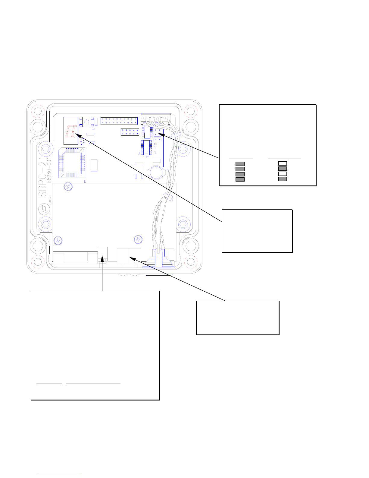
network, the jumpers shown below should be installed to provide network termination.
Figure 2-2: SBPC-21-PB Top View
These jumpers should be installed if the
SBPC-21-PB is at the end of a FifeNet
network. They provide network
termination. The other two jumpers
should always be installed as they
select half-duplex FifeNet
communication.
Terminated Not Terminated
Profibus Termination
The end nodes in a Profibus DP network must be
terminated to avoid reflections on the bus line. To
accomplish this, the Profibus DP module is equipped
with a termination switch. If the module is used as the
first or last module in a network, the termination switch
must be in the ON position. Otherwise, the switch
must be in the OFF position. If an external termination
connector is used, the switch must be in the OFF
position.
The termination dip switch can only be accessed with
the SBPC-21-PB top cover removed. To enable
termination, the switch must be in the OFF position.
Termination Switch Position
OFF Up toward top cover.
ON Down toward circuit board.
The 7-segment LED is
used to display errors or
exceptions. During normal
operation, the display will
continuously “cycle” the
outer segments.
Profibus node address switches.
See the following page for
description of these switches.
________________________________________________________________________________________________________________
12-20-2002 Figure Sheet 1-851-A Page 4

SBPC-21-PB External Connections/Switches/Indicators
SBPC-21-PB mounting considerations are simplified as all connections to the SBPC-21-PB are on the
same side of the box. The node address and rotary switches are accessible after removal of the plastic
hole plugs which should be reinstalled after configuration is completed.
Figure 1-3: SBPC-21-PB Side View
Connection to FifeNet is
accomplished using the
standard FifeNet
connector. Configuration
is also downloaded using
this connection.
LED indicators provide
feedback for network
troubleshooting.
Pin Name Signal
Housing Shield Connected to PE.
1 Not connected
2 Not connected
3 B-Line Positive RXD/TXD
4 RTS Request to Send1
5 GND BUS Isolated GND from RS-485 side1.
6
7 Not connected
8 A-Line Positive RXD/TXD
9 Not connected
1
+5V Bus and GND Bus are used for bus termination. Some
devices, like optical transceivers (RS485 to fiber optics), might
require external power from these pins. RTS is used in some
equipment to determine the direction of transmission. In normal
applications only A-Line, B-Line, and Shield are used.
+5V BUS Isolated +5VDC from RS-485
D-SUB Connector
1
.
side3
The Profibus Node address is set using these
rotary switches. This enables address settings
from 1-99 in decimal format. The left switch
sets the most significant digit and the right
switch sets the least significant digit. The node
address cannot be changed during operation.
Profibus DP Baud Rate
The baud rate on a Profibus DP network is set during configuration of the master. Only one baud rate
is possible in a Profibus DP installation. The SBPC-21-PB uses auto baud rate detection so the user
does not have to configure the baud rate. Baud rates supported are:
• 9.6 kbit/s • 187.5 kbit/s • 3 Mbit/s
• 19.2 kbit/s • 500 kbit/s • 6 Mbit/s
• 93.75 kbit/s • 1.5 Mbit/s • 12 Mbit/s
________________________________________________________________________________________________________________
12-20-2002 Figure Sheet 1-851-A Page 5

SBPC-21-PB Network Status
The SBPC-21-PB network status is determined by interpretation of the external LED status indicators
as described below.
Figure 1-4: SBPC-21-PB LED Indicators
Table 1-1
ONLINE
LED State Meaning
Green
Off Module is not ONLINE
LED State Meaning
Red
Off Module is ONLINE.
LED State Meaning
Off No faults present.
Flashing Red (1 Hz)
Flashing Red (2 Hz)
Flashing Red (4 Hz)
Indicates that the module is
ONLINE and data exchange is
possible.
OFFLINE
Indicates that the module is
OFFLINE and no data exchange is
possible.
FAULTS
Error in configuration: IN and/or
OUT length set during initialization
of the module is not equal to the
length set during configuration of the
network.
Error in user parameter data: The
length/contents of the user
parameter data set during
initialization of the module is not
equal to the length/contents set
during configuration of the network.
Error in initialization of the Profibus
communication ASIC.
________________________________________________________________________________________________________________
12-20-2002 Figure Sheet 1-851-A Page 6

SBPC-21-PB Error Codes
The 7-segment LED digit on the SBPC-21-PB main board is used to indicate errors or other potential
problems. See page 2 of this manual for the location of this LED. The error codes are divided into the
categories listed below. Since there is only a single-digit display and the error codes are 3 digits in
length, the error codes are displayed in three parts. The most significant digit will appear first followed
by the second and third digits. The display will go blank for a moment and the cycle repeats unless the
SBPC-21-PB has been configured to attempt to restart after an error. If this is the case, the error will
only cycle once. All state machine errors 5XX are considered nonfatal and only cycle once. Below are
the error codes and their meanings:
Table 1-2
SBPC PROCESSOR ERRORS
F01 Processor attempted to execute and undefined instruction.
F02 Software interrupt vector occurred.
F03 Attempt to fetch instruction from invalid memory.
F04 Attempt to read data from invalid memory.
F05 Reserved exception vector.
F06 FLASH memory checksum fault.
F07 Pool memory allocation error.
F08 Byte memory allocation error.
F09 Unable to create thread.
F0A Unable to create event.
F0B Unable to create semaphore.
F0C Unable to create mutex.
F0D Unable to create queue.
F0E Unable to write to queue.
F0F Console I/O error.
COMMUNICATION MODULE ERRORS
E01 The configuration matrix is corrupted.
E02 No HMS Anybus module detected.
E03 Anybus module failed to initialize (no interrupt received).
E04 Anybus module failed to initialize (interrupt stuck).
E05 Anybus module failed to initialize (mailbox not ready).
E06 Anybus mailbox timeout.
E07 Anybus mailbox response indicated error.
E08 Anybus mailbox response timeout.
E09 Anybus dual-port RAM fault.
E0A Anybus output area release timeout.
E0B Anybus initialization timeout.
STATE MACHINE ERRORS
501 State machine file is corrupted.
502 State machine is disabled.
503 State machine started in shutdown mode.
504 Bad state machine instruction encountered.
505 State machine instruction fetch from address is out of range.
506 State machine stack error (too many nested calls).
507 State machine stack error (too many returns).
508 State machine attempted divide by zero.
509 State machine tried to access more than four timers.
50A State machine variable address is out of range.
Errors that begin with ‘F’
are unrecoverable faults.
The SBPC cannot
participate in FifeNet or
Profibus operations. In
the default configuration
the SBPC will attempt to
restart.
Errors that begin with ‘E’
are associated with the
Profibus interface. In the
default configuration, the
SBPC will attempt to
restart. With the
exception of error ‘E01,’
FifeNet is functional;
however, the default
configuration will attempt
to restart which will
interrupt FifeNet.
Errors that begin with ‘5’
are related to the state
machine capability of the
SBPC. These errors are
cycled only once and do
not cause the SBPC to
restart.
________________________________________________________________________________________________________________
12-20-2002 Figure Sheet 1-851-A Page 7

________________________________________________________________________________________________________________
12-20-2002 Figure Sheet 1-851-A Page 8

SBPC-21-PB CUSTOMER INSTRUCTION MANUAL
2
FIFENET THEORY
• • • • • •
FifeNet Time Slices
Data on FifeNet is divided into time intervals called time slices. The FifeNet protocol runs in fixed
repeating cycles. Each time slice can transmit a single 16-bit value. All time slice values are updated
every cycle.
Multiplexed Time Slices
FifeNet devices can send a single 16-bit value in one or more time slices. This is acceptable for
values that require high performance such as guiding. The penalty for this performance is the usage
of one time slice per value sent. With limited time slices available, network bandwidth can be
consumed quickly. If some variables are not needed at a high rate, FifeNet offers a way to “multiplex”
a single time slice to carry multiple data words. There are two multiplex options available in the
CDP-01 permitting a single time slice to carry 16 words or 64 words. Multiplexing works by inserting
the specified data words in a sequential repeating cycle. The receiving SBPC-21-PB synchronizes
with the multiplexed data to extract it. This method trades data update speed for higher data quantities
(up to 64 words per time slice). Any combination of real-time or multiplexed data can exist on FifeNet.
Figure 2-1: Multiplexed Data Time Slices
D1 ACTIVITY
D1 is real-time. This data
is updated every cycle.
T0 T1 T2 T3
− −−−−−−−−−−−−−−−−− − −−−−−−−−−−−−−−−−− − −−−−−−−−−−−−−−−−− − −−−−−−−−−−−−−−−−−
D1 D5 D1 D5 D1 D5 D1 D5
MULTIPLEXING
D5 is multiplexed or switched to a
different variable every cycle.
After the last variable is sent, the
process repeats continuously.
Tn TS Contents
T0 - Edge Right Sensor
T1 - Line Edge Sensor
T2 - CDP Key Pressed
T3 - Status Register Common
T4 - Drive 1 Mode
T5 - Drive 1 Sensor Mode
T6 - Drive 1 Encoder
T7 - Drive 1 Status Reg 0
T8 - Drive 2 Mode
T9 - Drive 2 Sensor Mode
T10 - Drive 2 Encoder
T11 - Drive 2 Status Reg 0
T12 - Drive 3 Mode
T13 - Drive 3 Sensor Mode
T14 - Drive 3 Encoder
T15 - Drive 3 Status Reg 0
D5 ACTIVITY
________________________________________________________________________________________________________________
12-20-2002 Figure Sheet 1-851-A Page 9

In the example diagram (Figure 2-1), there is real-time data on D1 and 16 multiplexed data words on
D5. D1 contains the Edge Left Sensor value from a CDP-01. D5 is used to send 16 different values
from the CDP-01. For the real-time value, the CDP-01 sends the Edge Left Sensor value in D1 every
cycle. For the multiplexed time slice, the CDP-01 sends the Edge Right Sensor value in D5 during
time T0. During time T1, D5 contains the Line Edge Sensor value.
As you can see in the example on the previous page, 17 values are being sent over FifeNet, but only
two time slices of network bandwidth are used. The 16 values in time slice 5 are updated at a slower
rate than the value in time slice 1. The application dictates which method should be implemented.
FifeNet Master
The FifeNet protocol uses the time slice architecture described previously for configurable network
traffic. Without some synchronization, however, neither the SBPC-21-PB, nor the CDP-01, would
know where the time slice boundaries were located. This would create problems when they are trying
to send and receive data. This is one of the primary functions of the FifeNet Master, in this case, that
would be the SBPC-21-PB.
SBPC-21-PB Data Flow
In order to effectively connect two dissimilar networks, some means must be provided to collect the
data from each network and exchange it in a controlled manner so that no partial or incomplete data is
sent on either network. This is accomplished by using a block of memory in the SBPC-21-PB to
reassemble FifeNet time slice data and then, when it is complete, transfer it to the Profibus buffers for
transmission on Profibus. Keep in mind that the gateway has to be bidirectional so this process works
the same way for data traveling from Profibus to FifeNet. The diagram below shows the process:
Figure 2-2: SBPC-21-PB Data Flow Block Diagram
FifeNet
D1
D2
D3
•
•
•
•
•
•
•
•
The time slice
buffers hold
the raw time
slice data.
M
A
T
R
I
X
M
A
T
R
I
X
Profibus
Data
This matrix is used
to connect any time
slice to any memory
buffer location.
The memory array
is used to assemble
and hold data
passing through the
gateway.
This matrix is used to
connect Profibus
data to any memory
buffer location.
Profibus data is
placed here for
transmission. FifeNet
transmit data is read
from here and sent to
FifeNet.
________________________________________________________________________________________________________________
12-20-2002 Figure Sheet 1-851-A Page 10

As you can see in Figure 2-2, each time slice has enough memory to store 64 16-bit data words. This
is the maximum amount of data that appears on a FifeNet multiplexed time slice. These data words
are referenced by their order of reception in the multiplexed sequence with DW0 being first and DW63
being last. When the time slice is used in the real-time mode, only the first location DW0 in the
memory array is used. Multiplexed modes 4, 8, and 16 each use 4, 8, and 16 words of memory,
respectively.
________________________________________________________________________________________________________________
12-20-2002 Figure Sheet 1-851-A Page 11

________________________________________________________________________________________________________________
12-20-2002 Figure Sheet 1-851-A Page 12

A
A
A
SBPC-21-PB CUSTOMER INSTRUCTION MANUAL
3
CONFIGURATIONS
• • • • • •
Hardware Configuration - Single CDP-01
The SBPC-21-PB connection diagram is shown below. As you can see, this allows a single CDP-01 at
FifeNet address 1 and an SBPC-21-PB at FifeNet address 10. The SBPC-21-PB default Profibus
node address is 2, but can be easily changed using the rotary switches in the SBPC-21-PB.
Figure 3-1: SBPC-21-PB Network Connection With Single CDP-01
Profibus Node
ddress 2
FifeNet Master
ddress 10
FifeNet
FifeNet
ddress 1
Profibus Network
SBPC-21-PB to
CDP-01 Cable:
Fife P/N 68554-001
________________________________________________________________________________________________________________
12-20-2002 Figure Sheet 1-851-A Page 13

A
A
A
A
A
Hardware Configuration - Multiple CDP-01’s
In the network below, the default SBPC-21-PB configuration is used multiple times to provide control to
multiple CDP-01’s. Each SBPC-21-PB is connected to a single CDP-01 creating a separate FifeNet
network for each CDP-01. Each SBPC-21-PB appears as both a FifeNet node and a Profibus node.
Notice the SBPC-21-PB Profibus address must be different for each SBPC-21-PB. The Profibus
address is set by rotary switches accessible via holes in the connector side of the SBPC-21-PB.
Figure 3-2: SBPC-21-PB Network Connection With Multiple CDP-01’s
FifeNet Master
ddress 10
FifeNet
ddress 1
FifeNet Master
ddress 10
FifeNet
ddress 1
Profibus
ddress 3
FifeNet
SBPC-21-PB to
CDP-01 Cable:
Fife P/N 68554-001
Profibus Network
Software Configuration
Configurations have been created to match the single CDP-01 network shown in Figure 3-1. Since the
CDP-01 can have one, two, or three drives, a configuration has been created to match the parameters
present in each drive configuration. This prevents inefficient use of Profibus bandwidth for data that is
inapplicable. The three configurations are:
Table 3-1
CONFIGURATION
SBPC-21-PB Default Matrix for use with Single-Drive CDP-01 100410-02X 100246-02X
SBPC-21-PB Default Matrix for use with Dual-Drive CDP-01 100411-02X 100247-02X
SBPC-21-PB Default Matrix for use with Triple-Drive CDP-01 100412-02X 100248-02X
GSD File
A GSD file is provided with the SBPC-21-PB. Use this file when adding a new Profibus node to the network and
it will automatically set up the configuration for that network node. The table below indicates the quantity of data
transferred for single-, dual-, and triple-drive configurations.
Field Size Size Size Bit
Input 20 26 32 (16-bit)
Output 7 7 7 (16-bit)
SINGLE-
DRIVE
DUALDRIVE
SBPC-21-PB
MATRIX
TRIPLE-
DRIVE
CDP-01
MATRIX
________________________________________________________________________________________________________________
12-20-2002 Figure Sheet 1-851-A Page 14

SBPC-21-PB CUSTOMER INSTRUCTION MANUAL
4
COMMUNICATION MAPPING
• • • • • •
Profibus to FifeNet Data
In each of the three configurations (single-, dual-, or triple-drive CDP-01), the Profibus to FifeNet data
is the same. The table below shows the configuration mapping for data traveling from Profibus to
FifeNet. The control matrix data on data word 1 is present so that if it is mapped to the parallel input
for the CDP-01, a great deal of control can be exercised without a special state machine. If this control
is insufficient, the data capabilities on Data Words 2 through 6 provide for custom applications using
state machine interpretation.
SBPC-21-PB Matrix
100410-02X Single
100411-02X Dual
100412-02X Triple
Description
Network commands sent to the CDP-01.
Simulated key presses, etc.
Used to control the CDP-01 in accordance with
the control matrix.
These values are reserved for state machine
communication.
CDP-01 Matrix
100246-02X Single
100247-02X Dual
100248-02X Triple
Profibus Scheduled
Data Word Source
0 WORD Device 1 Command3
1 WORD Control Matrix
2 WORD [0] Reserved
3 WORD [1] Reserved
4 WORD [2] Reserved
5 INT [3] Reserved
6 INT [4] Reserved
Table 4-1
PROFIBUS TO FIFENET DATA — SINGLE-, DUAL-, AND TRIPLE-DRIVE
Variable
1
Data Type
2
2 = Data Types:
* INT 16-bit signed value in the range of –32,768 to +32,767.
* WORD 16-bit unsigned value in the range of 0 to 65,535.
3 = Commands to the CDP-01.
1 = All data words are 16-bit.
________________________________________________________________________________________________________________
12-20-2002 Figure Sheet 1-851-A Page 15

FifeNet to Profibus Data
The following single-, dual-, and triple-drive tables show the default configuration mapping for data
traveling from FifeNet to Profibus.
Single-Drive CDP-01
Table 4-2
FIFENET TO PROFIBUS DATA — SINGLE-DRIVE
CDP-01 Matrix: 100246-02X SBPC-21-PB Matrix: 100410-02X
Profibus
Scheduled
Data Word
Destination
1 = All data words are 16-bit.
2 = Data Types:
* INT 16-bit signed value in the range of –32,768 to +32,767.
* WORD 16-bit unsigned value in the range of 0 to 65,535.
* DWORD 32-bit unsigned value in the range of 0 to 4,294,967,295.
3 = This is the device response from the CDP-01.
1
0 WORD Reserved Reserved.
1
2
3
4
5 WORD Device 1 Response3 CDP-01 Fife network responses.
6 INT Edge Left Sensor Value Sensor signal.
7 INT Edge Right Sensor Value Sensor signal.
8 INT Line Center Sensor Value Sensor signal.
9 INT Line Edge Sensor Value Sensor signal.
10 WORD SM Command Feedback Reserved for state machine control.
11 WORD SM Status Feedback Reserved for state machine control.
12 WORD Common Status Register CDP-01 status.
13 WORD Key Pressed Current key pressed on CDP-01 panel.
14 WORD Drive 1 Operation Mode Drive 1 status.
15 WORD Drive 1 Sensor Mode Drive 1 status.
16 WORD Drive 1 Fault Register Drive 1 fault status.
17 WORD Drive 1 Encoder Register Drive 1 encoder status.
18 WORD Drive 1 Alarm Register Drive 1 alarm status.
19 INT Drive 1 Encoder Value Drive 1 encoder value.
Data Type
DWORD Reserved Reserved.
DWORD
2
Panel Data 0
Panel Data 1
Variable
CDP-01 LED panel data.
Description
________________________________________________________________________________________________________________
12-20-2002 Figure Sheet 1-851-A Page 16

Dual-Drive CDP-01
Table 4-3
FIFENET TO PROFIBUS DATA — DUAL-DRIVE
CDP-01 Matrix: 100247-02X SBPC-21-PB Matrix: 100411-02X
Profibus
Scheduled
Data Word
Destination
1 = All data words are 16-bit.
2 = Data Types:
* INT 16-bit signed value in the range of –32,768 to +32,767.
* WORD 16-bit unsigned value in the range of 0 to 65,535.
* DWORD 32-bit unsigned value in the range of 0 to 4,294,967,295.
3 = This is the device response from the CDP-01.
1
0 WORD Reserved Reserved.
1
2
3
4
5 WORD Device 1 Response3 CDP-01 Fife network responses.
6 INT Edge Left Sensor Value Sensor signal.
7 INT Edge Right Sensor Value Sensor signal.
8 INT Line Center Sensor Value Sensor signal.
9 INT Line Edge Sensor Value Sensor signal.
10 WORD SM Command Feedback Reserved for state machine control.
11 WORD SM Status Feedback Reserved for state machine control.
12 WORD Common Status Register CDP-01 status.
13 WORD Key Pressed Current key pressed on CDP-01 panel.
14 WORD Drive 1 Operation Mode Drive 1 status.
15 WORD Drive 1 Sensor Mode Drive 1 status.
16 WORD Drive 1 Fault Register Drive 1 fault status.
17 WORD Drive 1 Encoder Register Drive 1 encoder status.
18 WORD Drive 1 Alarm Register Drive 1 alarm status.
19 INT Drive 1 Encoder Value Drive 1 encoder value.
20 WORD Drive 2 Operation Mode Drive 2 status.
21 WORD Drive 2 Sensor Mode Drive 2 status.
22 WORD Drive 2 Fault Register Drive 2 fault status.
23 WORD Drive 2 Encoder Register Drive 2 encoder status.
24 WORD Drive 2 Alarm Register Drive 2 alarm status.
25 INT Drive 2 Encoder Value Drive 2 encoder value
Data Type
DWORD Reserved Reserved.
DWORD
2
Panel Data 0
Panel Data 1
Variable
Description
CDP-01 LED panel data.
________________________________________________________________________________________________________________
12-20-2002 Figure Sheet 1-851-A Page 17

Triple-Drive CDP-01
Table 4-4
FIFENET TO PROFIBUS DATA — TRIPLE-DRIVE
CDP-01 Matrix: 100248-02X SBPC-21-PB Matrix: 100412-02X
Profibus
Scheduled
Data Word
Destination
1 = All data words are 16-bit.
2 = Data Types:
* INT 16-bit signed value in the range of –32,768 to +32,767.
* WORD 16-bit unsigned value in the range of 0 to 65,535.
* DWORD 32-bit unsigned value in the range of 0 to 4,294,967,295.
3 = This is the device response from the CDP-01.
1
0 WORD Reserved Reserved.
1
2
3
4
5 WORD Device 1 Response3 Fife network response.
6 INT Edge Left Sensor Value Sensor signal.
7 INT Edge Right Sensor Value Sensor signal.
8 INT Line Center Sensor Value Sensor signal.
9 INT Line Edge Sensor Value Sensor signal.
10 WORD SM Command Feedback Reserved for state machine control.
11 WORD SM Status Feedback Reserved for state machine control.
12 WORD Common Status Register CDP-01 status.
13 WORD Key Pressed Current key pressed on CDP-01 panel.
14 WORD Drive 1 Operation Mode Drive 1 status.
15 WORD Drive 1 Sensor Mode Drive 1 status.
16 WORD Drive 1 Fault Register Drive 1 fault status.
17 WORD Drive 1 Encoder Register Drive 1 encoder status.
18 WORD Drive 1 Alarm Register Drive 1 alarm status.
19 INT Drive 1 Encoder Value Drive 1 encoder value.
20 WORD Drive 2 Operation Drive 2 status.
21 WORD Drive 2 Sensor Mode Drive 2 status.
22 WORD Drive 2 Fault Register Drive 2 fault status.
23 WORD Drive 2 Encoder Register Drive 2 encoder status.
24 WORD Drive 2 Alarm Register Drive 2 alarm status.
25 INT Drive 2 Encoder Value Drive 2 encoder value.
26 WORD Drive 3 Operation Mode Drive 3 status.
27 WORD Drive 3 Sensor Mode Drive 3 status.
28 WORD Drive 3 Fault Register Drive 3 fault status.
29 WORD Drive 3 Encoder Register Drive 3 encoder status.
30 WORD Drive 3 Alarm Register Drive 3 alarm status.
31 INT Drive 3 Encoder Value Drive 3 encoder value.
Data Type
DWORD Reserved Reserved.
DWORD
2
Panel Data 0
Panel Data 1
Variable
Description
CDP-01 LED panel data.
________________________________________________________________________________________________________________
12-20-2002 Figure Sheet 1-851-A Page 18

SBPC-21-PB CUSTOMER INSTRUCTION MANUAL
5
CONTROL INFORMATION
• • • • • •
CDP-01 Control Matrix
The CDP-01 parallel input matrix normally applies to the X7 port on the CDP-01. In the default matrix
using the SBPC-21-PB, the CDP-01 parallel input matrix is connected to a time slice. This connection
allows serial commands to be used to control the CDP-01 instead of the hardware parallel input. The
commands described in the control matrix tables on the following pages apply to the commands issued
from Profibus to FifeNet over the network via Data Word 1 in Table 4-1.
External Lock
There is one command, however, that the CDP-01 firmware will not accept over a serial connection for
safety reasons. This command is “EXTERNAL LOCK.” Even though the CDP-01 matrix has the
parallel inputs mapped to a FifeNet time slice, the EXTERNAL LOCK command is still activated by the
matrix shown below when this condition appears on the X7 port of the CDP-01. For multidrive
CDP-01’s, the command is applied to all drives present.
CDP-01 Parallel Input Matrix for Use with SBPC-21-PB
Table 5-1
INPUTS
Command Via X7 Parallel Port 5 4 3 2 1 0
External Lock (All drives applicable.) -- -- -- -- -- 1
Single-Drive CDP-01
CDP-01 Matrix: 100246-02X CDP-01 State Machine: 581000-020 SBPC-21-PB Matrix: 100410-02X
CDP-01 Control Matrix
Table 5-2
COMMAND VIA NETWORK HEX
DRIVE 1, AUTOMATIC 04
DRIVE 1, MANUAL 08
DRIVE 1, SERVO-CENTER 0C
DRIVE 1, JOG LEFT 10
DRIVE 1, JOG RIGHT 20
DRIVE 1, AUTO SETUP 30
DRIVE 1, RGPC SHIFT LEFT 18
DRIVE 1, RGPC SHIFT RIGHT 28
DRIVE 1, RGPC RESET 38
DRIVE 1, SENSOR EDGE LEFT 14
DRIVE 1, SENSOR EDGE RIGHT 24
DRIVE 1, SENSOR EDGE CENTER 34
DRIVE 1, SENSOR LINE CENTER 1C
DRIVE 1, SENSOR LINE EDGE 2C
DRIVE 1, SENSOR LINE E&C 3C
________________________________________________________________________________________________________________
12-20-2002 Figure Sheet 1-851-A Page 19

Dual-Drive CDP-01
CDP-01 Matrix: 100247-02X CDP-01 State Machine: 581000-020 SBPC-21-PB Matrix: 100411-02X
CDP-01 Control Matrix
Table 5-3
COMMAND VIA NETWORK HEX
DRIVE 1, AUTOMATIC 04
DRIVE 1, MANUAL 08
DRIVE 1, SERVO-CENTER 0C
DRIVE 1, JOG LEFT 10
DRIVE 1, JOG RIGHT 20
DRIVE 1, AUTO SETUP 30
DRIVE 1, RGPC SHIFT LEFT 18
DRIVE 1, RGPC SHIFT RIGHT 28
DRIVE 1, RGPC RESET 38
DRIVE 1, SENSOR EDGE LEFT 14
DRIVE 1, SENSOR EDGE RIGHT 24
DRIVE 1, SENSOR EDGE CENTER 34
DRIVE 1, SENSOR LINE CENTER 1C
DRIVE 1, SENSOR LINE EDGE 2C
DRIVE 1, SENSOR LINE E&C 3C
DRIVE 2, AUTOMATIC 05
DRIVE 2, MANUAL 09
DRIVE 2, SERVO-CENTER 0D
DRIVE 2, JOG LEFT 11
DRIVE 2, JOG RIGHT 21
DRIVE 2, AUTO SETUP 31
DRIVE 2, RGPC SHIFT LEFT 19
DRIVE 2, RGPC SHIFT RIGHT 29
DRIVE 2, RGPC RESET 39
DRIVE 2, SENSOR EDGE LEFT 15
DRIVE 2, SENSOR EDGE RIGHT 25
DRIVE 2, SENSOR EDGE CENTER 35
DRIVE 2, SENSOR LINE CENTER 1D
DRIVE 2, SENSOR LINE EDGE 2D
DRIVE 2, SENSOR LINE E&C 3D
________________________________________________________________________________________________________________
12-20-2002 Figure Sheet 1-851-A Page 20

Triple-Drive CDP-01
CDP-01 Matrix: 100248-02X CDP-01 State Machine: 581000-020 SBPC-21-PB Matrix: 100412-02X
CDP-01 Control Matrix
Table 5-4
COMMAND VIA NETWORK HEX
DRIVE 1, AUTOMATIC 04
DRIVE 1, MANUAL 08
DRIVE 1, SERVO-CENTER 0C
DRIVE 1, JOG LEFT 10
DRIVE 1, JOG RIGHT 20
DRIVE 1, AUTO SETUP 30
DRIVE 1, RGPC SHIFT LEFT 18
DRIVE 1, RGPC SHIFT RIGHT 28
DRIVE 1, RGPC RESET 38
DRIVE 1, SENSOR EDGE LEFT 14
DRIVE 1, SENSOR EDGE RIGHT 24
DRIVE 1, SENSOR EDGE CENTER 34
DRIVE 1, SENSOR LINE CENTER 1C
DRIVE 1, SENSOR LINE EDGE 2C
DRIVE 1, SENSOR LINE E&C 3C
DRIVE 2, AUTOMATIC 05
DRIVE 2, MANUAL 09
DRIVE 2, SERVO-CENTER 0D
DRIVE 2, JOG LEFT 11
DRIVE 2, JOG RIGHT 21
DRIVE 2, AUTO SETUP 31
DRIVE 2, RGPC SHIFT LEFT 19
DRIVE 2, RGPC SHIFT RIGHT 29
DRIVE 2, RGPC RESET 39
DRIVE 2, SENSOR EDGE LEFT 15
DRIVE 2, SENSOR EDGE RIGHT 25
DRIVE 2, SENSOR EDGE CENTER 35
DRIVE 2, SENSOR LINE CENTER 1D
DRIVE 2, SENSOR LINE EDGE 2D
DRIVE 2, SENSOR LINE E&C 3D
DRIVE 3, AUTOMATIC 06
DRIVE 3, MANUAL 0A
DRIVE 3, SERVO-CENTER 0E
DRIVE 3, JOG LEFT 12
DRIVE 3, JOG RIGHT 22
DRIVE 3, AUTO SETUP 32
DRIVE 3, RGPC SHIFT LEFT 1A
DRIVE 3, RGPC SHIFT RIGHT 2A
DRIVE 3, RGPC RESET 3A
DRIVE 3, SENSOR EDGE LEFT 16
DRIVE 3, SENSOR EDGE RIGHT 26
DRIVE 3, SENSOR EDGE CENTER 36
DRIVE 3, SENSOR LINE CENTER 1E
DRIVE 3, SENSOR LINE EDGE 2E
DRIVE 3, SENSOR LINE E&C 3E
________________________________________________________________________________________________________________
12-20-2002 Figure Sheet 1-851-A Page 21

Status Data Block
For reference, the CDP-01 Status Data Blocks are listed in the tables on the following pages:
NOTE: In the “Data Word Bit #” fields on the following tables: _ 0 = Low, 1 = High, Blank = Ignore
DW3, DW4: CDP-01 LED Panel Data
PANEL DATA WORD 0: DW3 PANEL DATA WORD 1: DW4
Bit CDP-01 LED Bit CDP-01 LED
0 LED 12 (Line Edge Sensor Mode 0
1 LED 11 (Line Center Sensor Mode) 1
2 LED 10 (Edge Right Sensor Mode) 2
3 LED 9 (Edge Left Sensor Mode) 3
4 LED 17 (Polarity) 4
5 LED 16 (Gain) 5
6 LED 15 (Guide Point) 6
7 LED 14 (Auto Setup) 7
8 8 LED 3 (Manual Key)
9 9 LED 2 (Servo-Center Key)
10 10 LED 1 (Auto Key)
11 Not Used 11 LED 8 (Sensor Key)
12 Drive 3 LED 12 LED 4 (F1 Key)
13 Drive 2 LED 13 LED 5 (F2 Key)
14 Drive 1 LED 14 LED 6 (F3 Key)
15 LED 13 (Setup Key) 15 LED 7 (ASC Key)
DW5: Device 1 Response
DEVICE 1 RESPONSE: DW5
Data Word Bit No.
15 14 13 12 11 10 9 8 7 6 5 4 3 2 1 0 Description
0 0 0 Automatic
0 0 1 Servo-Center
0 1 0 Manual
0 1 1 Jog Plus
1 0 1 Jog Minus
0 0 0 Edge Left
0 0 1 Edge Right
0 1 0 Center
0 1 1 Line Center
1 0 0 Line Edge
1 0 1 Line Edge & Center
0 0 Drive 1
0 1 Drive 2
1 0 Drive 3
________________________________________________________________________________________________________________
12-20-2002 Figure Sheet 1-851-A Page 22

Status Data Block (cont’d)
DW6: EDGE LEFT Sensor Value
DW7: EDGE RIGHT Sensor Value
DW8: LINE CENTER Sensor Value
DW9: LINE EDGE Sensor Value
NOTE: These data words contain the normalized values of the connected sensors.
Data Type: Signed 16-bit number
Range: -32,768 to +32,767
DW12: Common Status Register
COMMON STATUS REGISTER: DW12
Data Word Bit No.
15 14 13 12 11 10 9 8 7 6 5 4 3 2 1 0 Description
0 0 Drive 1 Panel Active
0 1 Drive 2 Panel Active
1 0 Drive 3 Panel Active
1
1
1
1 Drive 3 Installed
1
1 Drive 2 Installed
1 Status of Parallel Output A
1 Status of Parallel Output B
1 Status of Parallel Input 0
1 Status of Parallel Input 1
1 Status of Parallel Input 2
1 Status of Parallel Input 3
1 Status of Parallel Input 4
1 Status of Parallel Input 5
External A/D Converter
Installed
Bit = 1 indicates transistor on (output active).
Bit = 0 indicates transistor off (output inactive).
________________________________________________________________________________________________________________
12-20-2002 Figure Sheet 1-851-A Page 23

Status Data Block (cont’d)
DW13: Key Pressed
To ensure proper recognition, a key must be depressed for a minimum of 500 ms.
KEY PRESSED: DW13
Data Word Bit No.
Key 15 14 13 12 11 10 9 8 7 6 5 4 3 2 1 0 Hex Value
ASC 0 0x07FF
F3 0 0xBFFF
F2 0 0xDFFF
F1 0 0xEFFF
Sensor 0 0xF7FF
Automatic 0 0xFBFF
Servo-Center 0 0xFDFF
Manual 0 0xFEFF
Drive Select 0 0xFF7F
Setup 0 0xFFBF
Jog Plus 0 0xFFDF
Jog Minus 0 0xFFEF
RGPC Right 0 0xFFF7
RGPC Left 0 0xFFFB
Remote Calibration 0 0xFFFD
Error 0 0 0 0 0x0FFF
Timeout 0 0 0 0 0xF0FF
No Key Pressed 0 0 0 0 0xFF0F
Saving 0 0 0 0 0xFFF0
Undefined Key 0 0 0 0 0 0 0 0 0 0 0 0 0 0 0 0 0x0000
________________________________________________________________________________________________________________
12-20-2002 Figure Sheet 1-851-A Page 24

Status Data Block (cont’d)
DW14, DW20, DW26: Drive-Specific Operating Mode
DW14 – Drive 1
DW20 – Drive 2
DW26 – Drive 3
OPERATING MODE: DW14, DW20, DW26
Data Word Bit No.
15 14 13 12 11 10 9 8 7 6 5 4 3 2 1 0 Description
0 0 1 Automatic
0 1 0 Servo-Center
1 0 0 Manual
0 0 1 Jog Left
0 1 0 Jog Right
1 0 0 0 Setup (Auto or Man is Also Set)
DW15, DW21, DW27: Drive-Specific Sensor Selection and Temperature Fault
DW15 – Drive 1
DW21 – Drive 2
DW27 – Drive 3
SENSOR SELECTION: DW15, DW21, DW27
Data Word Bit No.
15 14 13 12 11 10 9 8 7 6 5 4 3 2 1 0 Description
0 0 0 0 0 1 Edge Left (X2)
0 0 0 0 1 0 Edge Right (X1)
0 0 0 1 0 0 Edge Center (X1 and X2)
0 0 1 0 0 0 Line Center (X3)
0 1 0 0 0 0 Line Edge (X3)
1 0 0 0 0 0 Line Edge and Center (X3 with VTB-20)
1 Fault – Overtemperature
________________________________________________________________________________________________________________
12-20-2002 Figure Sheet 1-851-A Page 25

Status Data Block (cont’d)
DW16, DW22, DW28: Drive-Specific Fault Register
DW16 – Drive 1
DW22 – Drive 2
DW28 – Drive 3
FAULT REGISTER (SR0): DW16, DW22, DW28
Data Word Bit No.
15 14 13 12 11 10 9 8 7 6 5 4 3 2 1 0 Description
1 Fault – Motor Drive Power Supply
1 Fault – Motor Overcurrent
1 Fault – +12V Power Supply
1 Fault – -12V Power Supply
1 Fault – Analog Ground
1 Fault – A/D Converter Initialization
1 Fault – Overtemperature
DW17, DW23, DW29: Drive -Specific Encoder Register
DW17 – Drive 1
DW23 – Drive 2
DW29 – Drive 3
ENCODER REGISTER (SR2): DW17, DW23, DW29
Data Word Bit No.
15 14 13 12 11 10 9 8 7 6 5 4 3 2 1 0 Description
1 Encoder – Counterclockwise Stroke Limit
1 Encoder – Clockwise Stroke Limit
1 Counterclockwise Web Measurement Limit
1 Clockwise Web Measurement Limit
1 Counterclockwise Limit Switch
1 Clockwise Limit Switch
________________________________________________________________________________________________________________
12-20-2002 Figure Sheet 1-851-A Page 26

Status Data Block (cont’d)
DW18, DW24, DW30: Drive-Specific Alarm Register
DW18 – Drive 1
DW24 – Drive 2
DW30 – Drive 3
ALARM REGISTER (SR3): DW18, DW24, DW30
Data Word Bit No.
15 14 13 12 11 10 9 8 7 6 5 4 3 2 1 0 Description
1 Encoder – Stroke Alarm
1 Web Measurement Alarm
1 Loss of Null
1 ASC (Automatic Sensor Control) Active
1 Fault – Serial Power
1 Drive Centered
1 Drive in Shutdown
1 Counterclockwise Maximum Motor Speed
1 Clockwise Maximum Motor Speed
1 Motor Blocked; Motor Current
1 SSC (Sensor Signal Comparator) Active
1 Counterclockwise Maximum Motor Current
1 Clockwise Maximum Motor Current
1 Valid Motor Installed
DW19: Drive 1 Encoder Value
DW25: Drive 2 Encoder Value
DW31: Drive 3 Encoder Value
NOTE: These data words contain the normalized values of the connected encoders.
Data Type: Signed 16 bit-number.
Range: -32,768 to +32,767
________________________________________________________________________________________________________________
12-20-2002 Figure Sheet 1-851-A Page 27

________________________________________________________________________________________________________________
12-20-2002 Figure Sheet 1-851-A Page 28

SBPC-21-PB CUSTOMER INSTRUCTION MANUAL
6
SPECIAL CONTROL OF FIFENET DEVICES
• • • • • •
NOTE: This section is intended to be used for special commands not available in the control matrix via
keypad emulation or for setup purposes.
CDP-01 Key Code Data Path
When a key is pressed on a FifeNet CDP-01, the key code goes through many steps before any action
is taken. The keys are scanned and the key is detected, but the key is not acted upon yet. Instead,
the key is buffered until the FifeNet Master polls the CDP-01 with a command that asks, “What keys
are pressed on your panel?” The CDP-01 responds with the key code representing which key (or
keys) are currently pressed. Normally, the FifeNet Master then issues a command back to the CDP-01
with the key code and a command that tells the CDP-01 which keys are pressed. Now that the
CDP-01 has received the command from the FifeNet Master telling it that a key has been pressed, it
will act on that key. (This is why a FifeNet CDP-01 keypad does not work when the network is down.)
Figure 6-1: CDP-01 Key Code Data Path
FifeNet Master
1) What keys are pressed?
2) My AUTO key is pressed.
3) Your AUTO key is pressed.
By skipping steps 1 and 2 in the sequence above, and injecting key codes/commands into the
command stream for the CDP-01, the SBPC-21-PB can simulate keys being pressed on the CDP-01’s
local panel. This provides the ability to make a fully functional remote control over the network.
________________________________________________________________________________________________________________
12-20-2002 Figure Sheet 1-851-A Page 29

CDP-01 Key Codes
The CDP-01 keypad is shown below, along with the key codes for each key. The key codes can be
used to send a command to the CDP-01 to simulate a key pressed on the CDP-01 keypad.
Commands are sent via a 16 bit command word, Register 0 in Table 4-1. Commands are issued by
placing an 8-bit “command” byte in the lower half of the command word and an 8-bit “action” byte in
the upper half of the command word. The “Key Pressed’ command is byte 0x13. The “Manual” key
code is 0x88. To simulate that the “Manual” key is pressed, send the command word 0x8813 to the
CDP-01. As long as the command is issued, the CDP-01 acts as though the key is being held down.
Even the actual keys on the CDP-01 keypad will be ignored until the command is cleared by writing
zero 0x0000 to the command word. This provides the ability to lock out the CDP-01 keypad. If local
keypad operation was needed concurrently with network control, the command should be maintained
until the correct feedback is obtained. Feedback is obtained by monitoring the CDP-01 status data
block parameters of Section 5. For instance, Register 0x40D could be monitored to verify that the key
pressed command was received and Register 0x405 could be monitored to see what the CDP-01
response was to the key pressed command.
Figure 6-2: CDP-01 Key Codes
Automatic 0xAA
Servo-Center 0x99
Manual 0x88
F1 0xCC
F2 0xDD
F3 0xEE
ASC 0xFF
Sensor 0xBB
Setup 0x66
Jog Minus 0x44
Drive Select 0x77
Jog Plus 0x55
KEY
HEX
CODE
Simulating Dual-Key Presses
It is also possible to simulate dual-key presses. Single-key presses contain values like 0x44 for “Jog
Minus” or 0x55 for “Jog Plus.” To simulate two keys pressed simultaneously, combine the two key
codes like this: “Jog Minus” combined with “Jog Plus” is 0x54. Any two keys can be combined as long
as the key code with the higher value is placed in the upper nibble. This allows simulation of setup
functions. Key combinations of three keys or more cannot be simulated by network commands.
________________________________________________________________________________________________________________
12-20-2002 Figure Sheet 1-851-A Page 30

CDP-01 LED Panel Data
To make remote control complete, we must have a way to duplicate the CDP-01 panel LED’s. The
CDP-01 keypad contains integrated LED’s to indicate operating modes, sensors selected, and many
other parameters. The CDP-01 can be configured to send its panel LED data over FifeNet so that
remote devices can duplicate the CDP-01 panel state. We have to look a little deeper to understand
how to use this capability.
Since there are 31 LED’s on the CDP-01 panel, the information has to use the multiplexed mode to
send all the LED states. The CDP-01 sends the panel data in two parts: Input Registers 0x403 and
0x404 as shown in Section 5, Status Data Block. The first word (Input Register 0x403) contains the
state of 15 panel LED’s, while the second word (Input Register 0x404) contains the remaining 16 LED
states. The logic is negative so a bit that is zero indicates that this LED is on.
By using the panel data, the setup procedures in the CDP-01 reference manual can be monitored to
ensure proper sequence of steps.
Figure 6-3: CDP-01 LED Panel Data
________________________________________________________________________________________________________________
12-20-2002 Figure Sheet 1-851-A Page 31

________________________________________________________________________________________________________________
12-20-2002 Figure Sheet 1-851-A Page 32

SBPC-21-PB CUSTOMER INSTRUCTION MANUAL
7
INDEX
• • • • • •
Address
FifeNet....................................................... 4
Profibus ..................................................... 4
CDP-01
Commands........................................ 29, 30
Key Codes............................................... 30
LED Panel Data ...................................... 31
Parallel Input ........................................... 19
Simulating Dual-Key Press ..................... 30
Codes
CDP-01, Key ..................................... 29, 30
Error Codes............................................... 7
Commands
FifeNet to Profibus, Dual ......................... 17
FifeNet to Profibus, Single ......................16
FifeNet to Profibus, Triple ....................... 18
Profibus to FifeNet, Dual ......................... 20
Profibus to FifeNet, Single ......................19
Profibus to FifeNet, Triple .......................21
Special ....................................................29
Configuration
CDP-01, Multiple ..................................... 14
CDP-01, Single ....................................... 13
Drive, FifeNet to Profibus ........................ 16
Drive, Profibus to FifeNet ........................ 15
Network ................................................... 13
Switch/Jumper........................................... 4
Connections
FifeNet....................................................... 5
Network ..................................................... 1
Consumer .....See Producer/Consumer Model
Control Matrix
Dual-Drive ............................................... 20
Single-Drive............................................. 19
Triple-Drive.............................................. 21
Data Flow.................................................... 10
Data Mapping
Profibus to FifeNet ..................................15
Data Transfer.............................................. 10
Error Codes ..................................................7
FifeNet
Definition....................................................3
Master......................................................10
GSD File......................................................14
Indicators
Channel Status ..........................................6
Network Status ..........................................6
Jumpers ........................................................4
Key Codes
CDP-01..............................................29, 30
LED’s
7-Segment .................................................7
Error.......................................................6, 7
Status ........................................................6
Matrix Files..................................................14
Network
Node Setup ...............................................14
Status ........................................................6
Panel Data
CDP-01....................................................31
Parallel Input
CDP-01....................................................19
Produced Data
Dual-Drive................................................17
Single-Drive .............................................16
Triple-Drive ..............................................18
Producer....... See Producer/Consumer Model
Producer/Consumer Model ...........................3
Profibus
Node.........................................................14
SBPC-21-DN
Definition....................................................1
Software
Matrix Files ..............................................14
Parallel Input Matrix.................................19
State Machine..........................................15
Status Data Block
DW12, Common Status Register ............23
DW13, Key Pressed ................................24
DW14, Drive 1 Operating Mode ..............25
________________________________________________________________________________________________________________
12-20-2002 Figure Sheet 1-851-A Page 33

DW15, Drive 1 Sensor Selection............. 25
DW16, Drive 1 Fault Register ................. 26
DW17, Drive 1 Encoder Register ............ 26
DW18, Drive 1 Alarm Register ................ 27
DW19, Drive 1 Encoder Value ................ 27
DW20, Drive 2 Operating Mode .............. 25
DW21, Drive 2 Sensor Selection............. 25
DW22, Drive 2 Fault Register ................. 26
DW23, Drive 2 Encoder Register ............ 26
DW24, Drive 2 Alarm Register ................ 27
DW25, Drive 2 Encoder Value ................ 27
DW26, Drive 3 Operating Mode .............. 25
DW27, Drive 3 Sensor Selection............. 25
DW28, Drive 3 Fault Register ................. 26
DW3, CDP-01 Panel Data Word 0 ..........22
DW30, Drive 3 Alarm Register ................27
DW31, Drive 3 Encoder Value.................27
DW4, CDP-01 Panel Data Word 1 ..........22
DW5, Device 1 Response .......................22
DW6, EDGE LEFT Sensor Value ............23
DW7, EDGE RIGHT Sensor Value..........23
DW8, LINE CENTER Sensor Value ........23
DW9, LINE EDGE Sensor Value.............23
Switch Settings..............................................5
Time Slices
Multiplexed ................................................9
Real-Time ..................................................9
________________________________________________________________________________________________________________
12-20-2002 Figure Sheet 1-851-A Page 34

 Loading...