

FIFE CORPORATION
222 W. Memorial Road, Oklahoma City, OK 73126-0508
Post Office Box 26508, Oklahoma City, OK 73114-2317
Phone: 405.755.1600 / 800.639.3433 / Fax: 405.755.8425
www.fife.com / E-mail: fife@fife.com
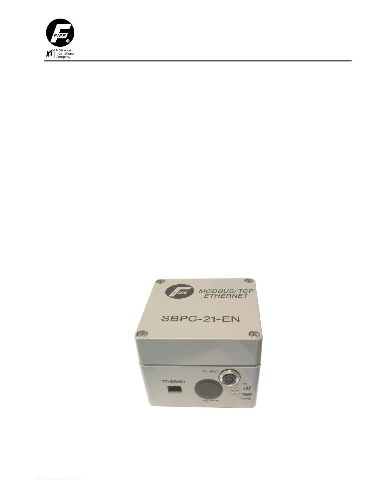
SBPC-21-EN
FifeNet To Ethernet Gateway
Customer Instruction Manual
Modbus/TCP Ethernet
© 2004 Fife Corporation. All rights reserved.

07-02-2004 Figure Sheet 1-849-C

SBPC-21-EN CUSTOMER INSTRUCTION MANUAL
COPYRIGHT
• • • • • •
All rights reserved. Any reproduction of this Instruction Manual, in any form in whole or in part requires
the prior written consent of Fife Corporation.
The information given in this Instruction Manual is subject to change without notice.
We have compiled this Instruction Manual with the greatest possible care and attention. However, the
possibility of error cannot be completely excluded. Fife Corporation accepts no legal liability for
incorrect information given and the consequences arising there from.
MS DOS is a trademark of Microsoft Corporation.
07-02-2004 Figure Sheet 1-849-C Page i

07-02-2004 Figure Sheet 1-849-C Page ii

SBPC-21-EN CUSTOMER INSTRUCTION MANUAL
TABLE OF CONTENTS
• • • • • •
INTRODUCTION ......................................................................................................................................... 1
PRODUCER/CONSUMER MODEL .................................................................................................................1
FIFENET....................................................................................................................................................1
SBPC-21-EN SWITCH/JUMPER CONFIGURATION .......................................................................................2
SBPC-21-EN EXTERNAL CONNECTIONS/INDICATORS ................................................................................3
SBPC-21-EN NETWORK STATUS ..............................................................................................................4
SBPC-21-EN ERROR CODES ....................................................................................................................5
TCP/IP FEATURES ....................................................................................................................................6
SBPC-21-EN NETWORK CONFIGURATION .................................................................................................6
IP ADDRESS..............................................................................................................................................6
SUBNET MASK...........................................................................................................................................6
SPECIAL CASE IP ADDRESSES ...................................................................................................................6
CONFIGURING IP ADDRESS........................................................................................................................7
USING CONFIGURATION SWITCH ................................................................................................................7
USING DHCP/BOOTP................................................................................................................................7
USING A PREDEFINED CONFIGURATION ......................................................................................................7
USING ADDRESS RESOLUTION PROTOCOL (ARP).......................................................................................8
FILE SYSTEM .............................................................................................................................................9
CONFIGURATION FILE ETHCFG.CFG ............................................................................................................9
TELNET SUPPORT .................................................................................................................................10
MODBUS TCP .........................................................................................................................................11
F
IFENET THEORY ................................................................................................................................... 13
FIFENET TIME SLICES..............................................................................................................................13
MULTIPLEXED TIME SLICES ......................................................................................................................13
FIFENET MASTER ....................................................................................................................................14
SBPC-21-EN DATA FLOW.......................................................................................................................15
ONFIGURATIONS................................................................................................................................... 17
C
HARDWARE CONFIGURATION – SINGLE CDP-01.......................................................................................17
HARDWARE CONFIGURATION – MULTIPLE CDP-01’S ................................................................................18
SOFTWARE CONFIGURATION....................................................................................................................18
C
OMMUNICATION MAPPING..................................................................................................................... 19
MODBUS TO FIFENET DATA .....................................................................................................................19
FIFENET TO MODBUS DATA .....................................................................................................................20
C
ONTROL INFORMATION ......................................................................................................................... 23
CDP-01 CONTROL MATRIX......................................................................................................................23
EXTERNAL LOCK......................................................................................................................................23
SINGLE-DRIVE CDP-01 ...........................................................................................................................23
DUAL-DRIVE CDP-01 ..............................................................................................................................24
TRIPLE-DRIVE CDP-01............................................................................................................................25
STATUS DATA BLOCK ..............................................................................................................................26
07-02-2004 Figure Sheet 1-849-C Page iii

S
PECIAL CONTROL OF FIFENET DEVICES.................................................................................................33
CDP-01 KEY CODE DATA PATH...............................................................................................................33
CDP-01 KEY CODES ...............................................................................................................................34
SIMULATING DUAL-KEY PRESSES.............................................................................................................34
CDP-01 LED PANEL DATA......................................................................................................................35
NDEX......................................................................................................................................................37
I
07-02-2004 Figure Sheet 1-849-C Page iv
SBPC-21-EN CUSTOMER INSTRUCTION MANUAL
1
INTRODUCTION
• • • • • •
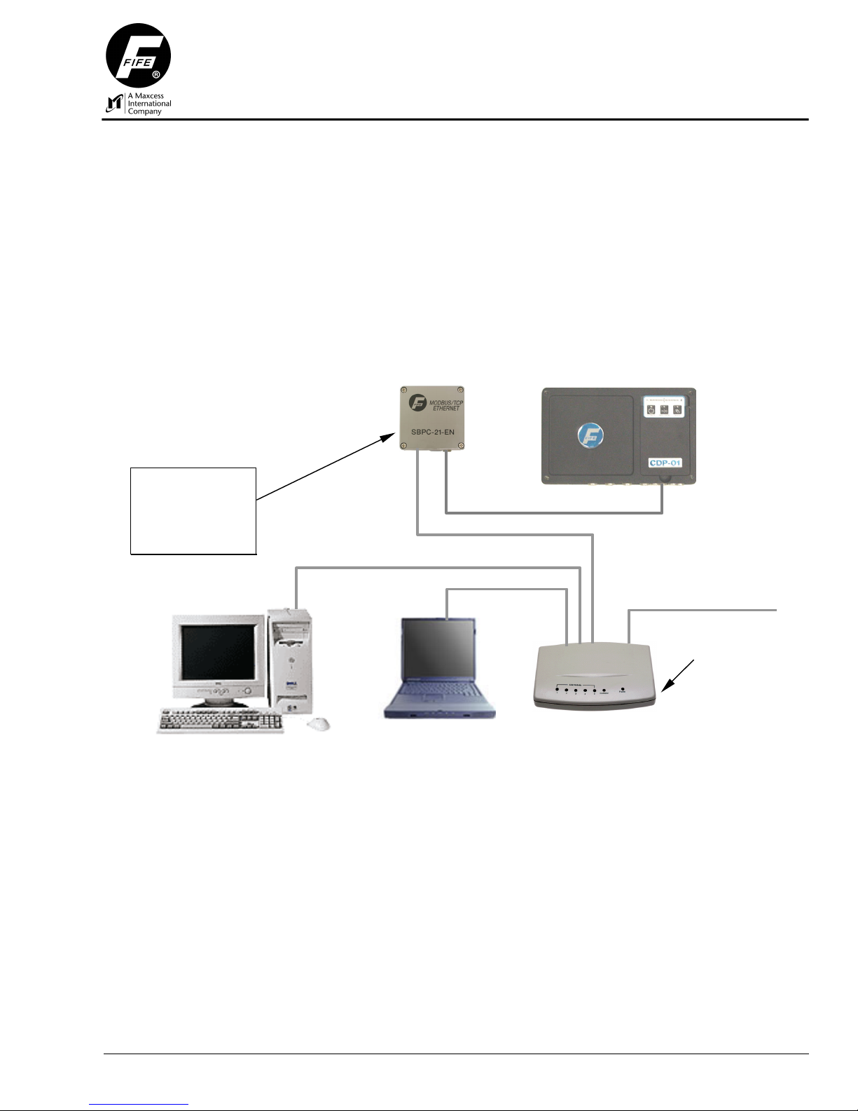
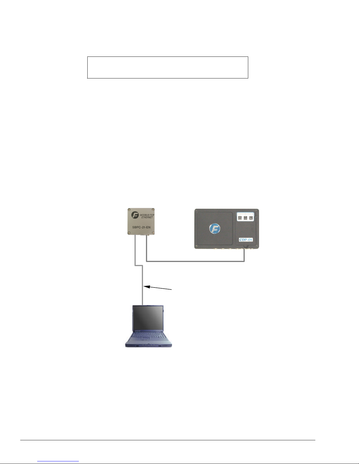
The Fife SBPC-21-EN (Serial Bus Protocol Converter) provides a gateway between Fife’s proprietary
FifeNet network and an Ethernet network. The SBPC-21-EN uses the standard RJ-45 connector and
conforms to the Modicon Open Modbus/TCP Specification, Release 1.0 (March 29, 1999). As shown
in the diagram below, the SBPC-21-EN connects to both FifeNet and Ethernet.
Figure 1-1: SBPC-21-EN Network Connection
The SBPC-21-EN
connects to both
FifeNet and Ethernet
providing translation
between the two
networks.
Producer/Consumer Model
The Producer/Consumer model allows the exchange of information between a sending device
(“producer”) and many receiving devices (“consumer”) without requiring the same date to be sent
multiple times to different destinations. The producer sends the data once and each consumer on the
network receives the data at the same time. The data can be used (consumed) or ignored by each
receiving device independently. FifeNet uses the Producer/Consumer Model.
FifeNet
FifeNet’s deployment of the Producer/Consumer Model allows data sent by a single device to be
received simultaneously by multiple devices on the same network. Each receiving device can choose
to use (consume) the information or ignore it as needs dictate. FifeNet is based on a fixed time slicing
architecture where transmitting devices send data in fixed, predetermined time intervals.
FifeNet
Customer
Ethernet
Ethernet Hub
07-02-2004 Figure Sheet 1-849-C Page 1
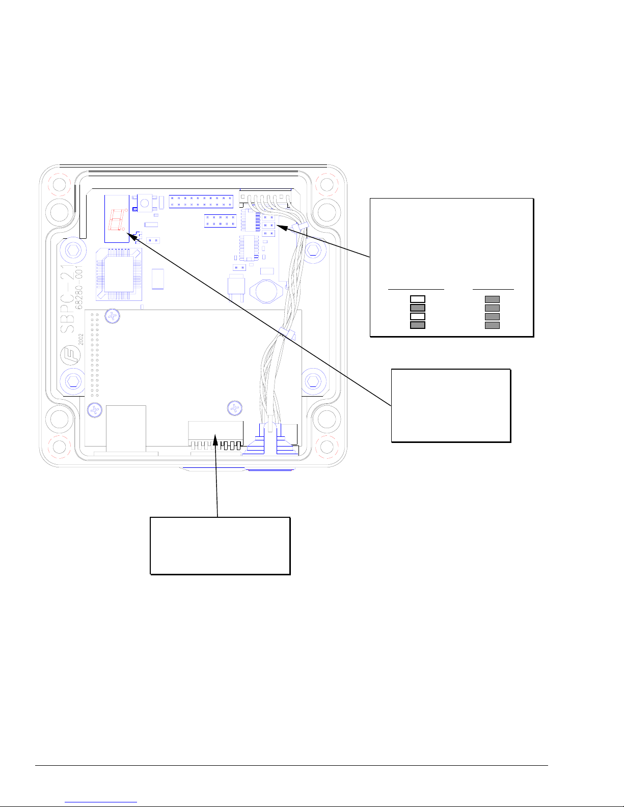
SBPC-21-EN Switch/Jumper Configuration
Since the SBPC-21-EN participates in two networks at the same time, it must have two network
addresses (a FifeNet address and an Ethernet IP address). The FifeNet address is set via the FifeNet
serial port that is common with many FifeNet peripherals. The Ethernet IP address is programmable
by dipswitches or via the Ethernet connection. See the dipswitch description and IP address
configuration setup shown below for more information. If the SBPC-21-EN is installed as the end point
in a FifeNet network, all four jumpers described below should be installed.
Figure 1-2: SBPC-21-EN Top View
These jumpers should be installed if the
SBPC-21-EN is at the end of a FifeNet
network. They provide network
termination. The other two jumpers
should always be installed as they
select half-duplex FifeNet
communication.
Not Terminated Terminated
The 7-segment LED is
used to display errors or
exceptions. During normal
operation, the display will
continuously “cycle” the
outer segments.
The Ethernet IP address
configuration switches. See the
following page for description of
these switches.
07-02-2004 Figure Sheet 1-849-C Page 2
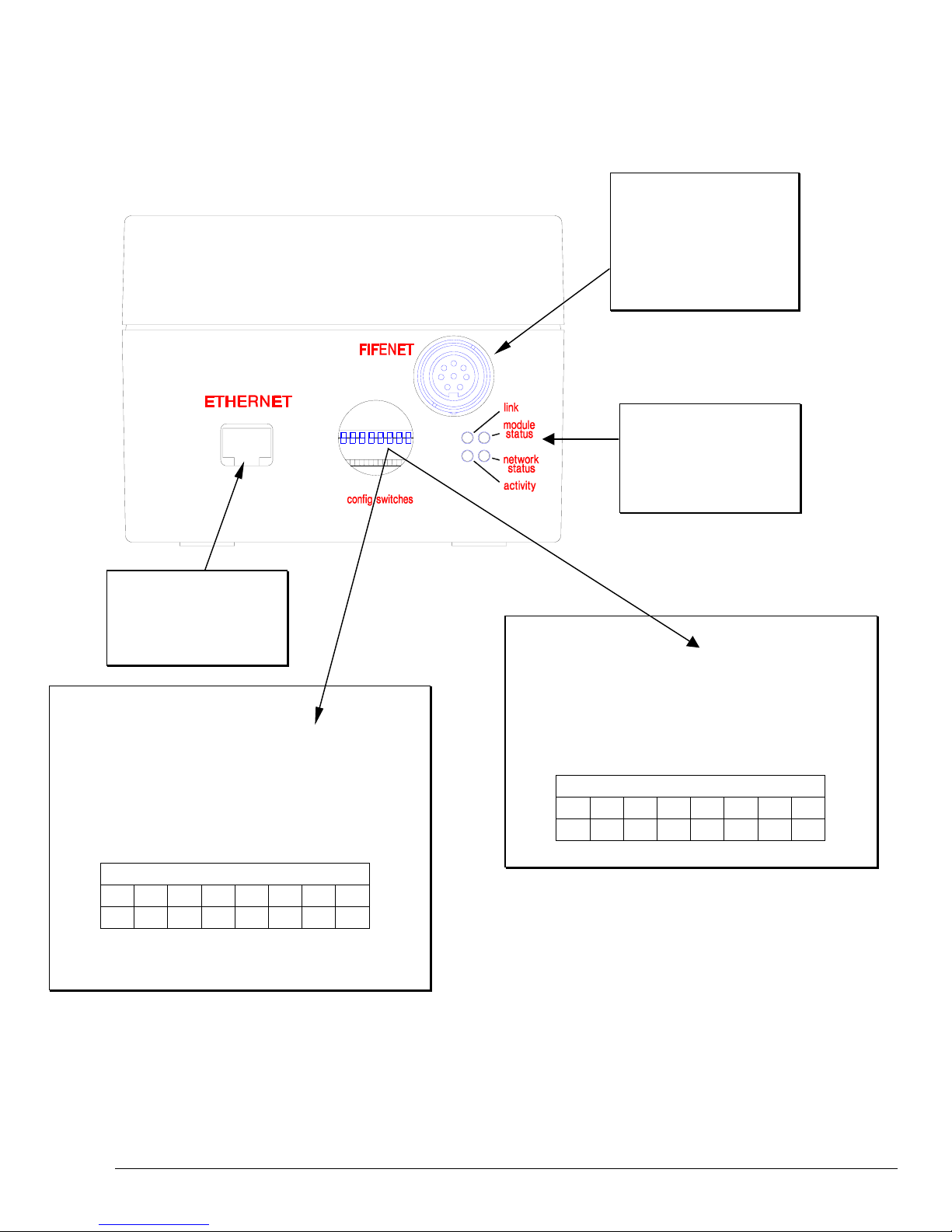
SBPC-21-EN External Connections/Indicators
SBPC-21-EN mounting considerations are simplified as all connections to the SBPC-21-EN are on the
same side of the box.
Figure 1-3: SBPC-21-EN Side View
Connection to FifeNet is
accomplished using the
standard FifeNet connector.
Configuration is also
downloaded to the device
using this connection.
Device and network status
LED’s. These indicators
provide feedback for
network troubleshooting.
Connection to Ethernet is
accomplished using the
standard RJ-45 connector.
Switch Value = 1-255
The IP address configuration switches can be used to configure
the IP address in an intranet network. The first three values of
the IP address are fixed at 192.168.0 and the dip switch value
represents the binary value of the last digit of the IP address.
The subnet mask is 255.255.255.0 and the default Gateway is
0.0.0.0.
In the switch example shown above, the IP address is set to
192.168.0.20.
1 2 3 4 5 6 7 8
OFF OFF OFF ON OFF ON OFF OFF
Switch
Switch Value = 0
Set the switches to zero as shown below to use a
DHCP/BootP server if present or use the internally stored IP
address. If a DHCP/BootP server is not present, the stored IP
address will be used. See the section SBPC-21-EN Network
Configuration for details about how to store an IP address.
1 2 3 4 5 6 7 8
OFF OFF OFF OFF OFF OFF OFF OFF
Switch
07-02-2004 Figure Sheet 1-849-C Page 3

SBPC-21-EN Network Status
The SBPC-21-EN network status is determined by interpretation of the external LED status as
described in the table below.
Figure 1-4: SBPC-21-EN LED Indicators
Table 1-1
LINK LED
LED State Meaning
Off Ethernet network not detected.
Solid Green The SBPC-21-EN is connected to an Ethernet network.
MODULE STATUS
LED State Meaning
Off SBPC-21-EN initializing.
Flashing Green The Ethernet IP address is NOT configured by the dip switches.
Flashing Red (1 Hz) Invalid MAC ID (Internal error).
Flashing Red (2 Hz) Failed to load Ethernet configuration from internal FLASH.
Flashing Red (4 Hz) Internal error.
Solid Red Duplicate IP address detected.
NETWORK STATUS
LED State Meaning
Off No Modbus/TCP connections are established.
Flashing Green
This LED flashes green to indicate the number of Modbus/TCP connections that
are currently active to the SBPC-21-EN. The number of flashes is equal to the
number of connections.
ACTIVITY LED
LED State Meaning
N/A The ACTIVITY LED flashes green when a packet is received or transmitted.
07-02-2004 Figure Sheet 1-849-C Page 4

SBPC-21-EN Error Codes
The 7-segment LED digit on the SBPC-21-EN main board is used to indicate errors or other potential
problems. See page 2 of this manual for the location of this LED. The error codes are divided into the
categories listed below. Since there is only a single-digit display and the error codes are 3 digits in
length, the error codes are displayed in three parts. The most significant digit will appear first followed
by the second and third digits. The display will go blank for a moment and the cycle repeats unless the
SBPC-21-EN has been configured to attempt to restart after an error. If this is the case, the error will
only cycle once. All state machine errors 5XX are considered nonfatal and only cycle once. Below are
the error codes and their meanings.
Table 1-2
SBPC PROCESSOR ERRORS
F01 Processor attempted to execute and undefined instruction.
F02 Software interrupt vector occurred.
F03 Attempt to fetch instruction from invalid memory.
F04 Attempt to read data from invalid memory.
F05 Reserved exception vector.
F06 FLASH memory checksum fault.
F07 Pool memory allocation error.
F08 Byte memory allocation error.
F09 Unable to create thread.
F0A Unable to create event.
F0B Unable to create semaphore.
F0C Unable to create mutex.
F0D Unable to create queue.
F0E Unable to write to queue.
F0F Console I/O error.
COMMUNICATION MODULE ERRORS
E01 The configuration matrix is corrupted.
E02 No HMS Anybus module detected.
E03 Anybus module failed to initialize (no interrupt received).
E04 Anybus module failed to initialize (interrupt stuck).
E05 Anybus module failed to initialize (mailbox not ready).
E06 Anybus mailbox timeout.
E07 Anybus mailbox response indicated error.
E08 Anybus mailbox response timeout.
E09 Anybus dual-port RAM fault.
E0A Anybus output area release timeout.
E0B Anybus initialization timeout.
STATE MACHINE ERRORS
501 State machine file is corrupted.
502 State machine is disabled.
503 State machine started in shutdown mode.
504 Bad state machine instruction encountered.
505 State machine instruction fetch from address is out of range.
506 State machine stack error (too many nested calls).
507 State machine stack error (too many returns).
508 State machine attempted divide by zero.
509 State machine tried to access more than four timers.
50A State machine variable address is out of range.
Errors that begin with ‘F’
are unrecoverable faults.
The SBPC cannot
participate in FifeNet or
Ethernet operations. In
the default configuration,
the SBPC will attempt to
restart.
Errors that begin with ‘E’
are associated with the
Ethernet interface. In
the default configuration,
the SBPC will attempt to
restart. With the
exception of error ‘E01,’
FifeNet is functional;
however, the default
configuration will attempt
to restart which will
interrupt FifeNet.
Errors that begin with ‘5’
are related to the state
machine capability of the
SBPC. These errors are
cycled only once and do
not cause the SBPC to
restart.
07-02-2004 Figure Sheet 1-849-C Page 5

TCP/IP Features
The SBPC-21-EN supports the following TCP/IP features:
• Modbus/TCP Supports Modicon Open Modbus/TCP specification, Release 1.0.
• BOOTP/DHCP bootstrap address resolution.
• File system with approximately 1.4Mbytes of space available.
• TELNET server featuring a command line interface similar to MS DOS™.
• FTP server provides easy file management using standard FTP clients.
• ICMP echo request (ping).
SBPC-21-EN Network Configuration
Before you can use the module on your network, you must configure the IP address, the subnet mask,
and optionally, the gateway address.
IP Address
The IP address is used to identify each node on the TCP/IP network. Therefore, each node on the
network must have a unique IP address. IP addresses are written as four decimal integers (0-255)
separated by periods, where each integer represents the binary value of one byte in the IP address.
This is called dotted-decimal notation.
Example:
Address 10000000 00001010 00000010 00011110 is written as 128.10.2.30
Subnet Mask
The IP address is divided into three parts: net ID, subnet ID, and host ID. To separate the net ID and
the subnet ID from the host ID, a subnet mask is used. The subnet mask is a 32-bit binary pattern,
where a set bit allocates a bit for network/subnet ID and a cleared bit allocates a bit for the host ID.
Like the IP address, the subnet mask is commonly written in dotted-decimal notation.
Example:
To make the IP address 128.10.2.30 belong to subnet 128.10.2, the subnet mask shall
be set to 255.255.255.0.
Subnet Mask: 11111111 11111111 1111111 00000000 (255.255.255.0)
Note: To be able to establish communication between two devices, both devices must belong to the
same subnet. If not, the communication must be done through a gateway. It is, therefore,
recommended to configure the module to the same subnet as your PC.
Special Case IP Addresses
Devices on an Ethernet network are not allowed to be configured to the following IP addresses;
therefore, do not configure the SBPC-21-EN to use any of them.
IP ADDRESS DESCRIPTION
0.X.X.X
127.X.X.X
X.X.X.0
X.X.X.255
IP address where the first byte is zero
IP address where the first byte is 127.
IP address where the last byte is zero.
IP address where the last byte is 255.
07-02-2004 Figure Sheet 1-849-C Page 6
A
Configuring IP Address
The module offers several ways to configure the IP address:
• Configuration Switch
• DHCP/BootP
• Using a predefined IP address stored in FLASH.
• ARP
Using Configuration Switch
The configuration switch provides an easy way to configure the module for intranet use. The switch
represents the binary value of the last byte in the IP address. If the switch is set to a value between 1255, the module will use the settings described below:
IP ADDRESS DESCRIPTION
IP Address 192.168.0.n1
Subnet Mask2 255.255.255.0
Gateway Address2 0.0.0.0 (No gateway set).
1
n represents the binary value of the configuration switches.
2
The subnet mask and gateway are fixed to these values when using the
configuration switch to set the IP address.
1 2 3 4 5 6 7 8
OFF OFF OFF ON OFF ON OFF OFF
Note: These settings can only be used on an intranet. This is because the IP address that is being set
belongs to the private address set, see RFC 1918.
Switch
Example:
The switches are set to 00010100 (20 decimal)
The IP address of the module will be set to 192.168.0.20
Using DHCP/BootP
If the configuration switches are set to 0, the SBPC-21-EN will read the configuration stored in FLASH.
If DHCP/BootP is enabled and a DHCP or BootP server is found, the IP address, subnet mask, and
gateway are automatically configured by the DHCP/BootP server. DHCP/BootP must be enabled by
modification of the file ethcfg.cfg in the internal file system. See the file system section for information
about this file and how to change it.
1 2 3 4 5 6 7 8
OFF OFF OFF OFF OFF OFF OFF OFF
Switch
ll switches in the position shown (0) uses DHCP/BootP
or internal configuration.
Using a Predefined Configuration
If the configuration switches are set to 0, the SBPC-21-EN will read the configuration stored in internal
FLASH. If DHCP/BootP is disabled or a DHCP/BootP client cannot be found, the SBPC-21-EN will try
to use the configuration stored in FLASH. If no configuration is found, the SBPC-21-EN will indicate an
error on the Network Status LED. In this state, the SBPC-21-EN will only run the ARP protocol.
07-02-2004 Figure Sheet 1-849-C Page 7
Using Address Resolution Protocol (ARP)
The IP address can be changed during runtime using the ARP command from a PC. The new IP
address will also be stored in internal FLASH. Below is an example on how to change the IP address
from an MS DOS™ window:
arp -s <IP address>1 <MAC address>2
ping <IP address>
arp -d <IP address>
1
The IP Address to assign to the SBPC-21-EN.
2
The 6-digit MAC address from the label on the SBPC-21-EN.
1
1
The arp -s command will store the IP and MAC addresses in the PC’s ARP table. When the ping
command is executed, the PC sends this information to the SBPC-21-EN using the MAC address. The
module detects that it was addressed with the correct MAC address and adopts the IP address sent by
the PC. The new IP address will also be stored in internal FLASH. (The arp -d command is optional,
but it removes the static route from the PC ARP table.) This method can be used to reconfigure
modules that already have been configured. The MAC address is printed on a label on the bottom side
of the SBPC-21-EN.
Note: As the arp command automatically configures the subnet mask to 255.255.255.0, the first three
bytes of the IP address must be the same as for the PC executing the command.
Figure 1-4: Example Connection Using ARP to Change SBPC-21-EN IP Address
SBPC-21-EN MAC ID:
00-aa-00-62-c6-09
Desired IP Address
84.83.83.5
FifeNet provides power for SBPC-21-EN.
Ethernet crossover cable allows
direct connection to SBPC-21-EN.
PC’s IP address is 84.83.83.2
In the above example, the following commands would set the SBPC-21-EN IP address to 84.83.83.5.
arp –s 84.83.83.5 00-aa-00-62-c6-09
ping 84.83.83.5
arp –d 84.83.83.5
07-02-2004 Figure Sheet 1-849-C Page 8

File System
The file system is a fixed-size storage area with a hierarchical directory structure. Files can be grouped
in directories for readability. The file system features two security levels. Depending on security level,
different users can have access to different files and directories. The file system is accessible via FTP
and TELNET.
Case Sensitivity
The file system is case sensitive.
File Name / Path Name Length
File names can be a maximum of 48 characters long. Path names can be 256
characters in length, including the file name.
File Size
The file size is not restricted. Naturally, a file cannot be larger than the available
space (see below).
Free Space
There is approximately 1.4 Mb available for user files.
Configuration File ethcfg.cfg
This file contains the network configuration and is read during initialization. It is an ASCII text file that
may be edited with any text editor. If DHCP/BootP configuration is needed, this file must be modified to
be enabled. Once changed, the SBPC-21-EN needs to be restarted for changes to take effect. The
format of the file is shown below:
Example :
ethcfg.cfg file:
[IP Address]
IP address.
10.10.12.212
[Subnet Mask]
Subnet mask.
255.255.255.0
[Gateway Address]
Gateway address.
0.0.0.0
[SMTP Address]
N/A
0.0.0.0
[DHCP/BOOTP]
OFF
ON = Enabled.
OFF= Disabled.
[Speed]
Auto
Auto - Default. Auto negotiation will be used.
100 - Forces the module to operate only at 100 Mbit
10 - Forces the module to operate only at 10 Mbit
[Duplex]
Auto
Auto - Default. Auto negotiation will be used.
Full - Forces the module to operate only at full duplex
Half - Forces the module to operate only at half duplex
Using a standard FTP client, this file can be transferred from the SBPC-21-EN to a PC, edited, and
sent back.
07-02-2004 Figure Sheet 1-849-C Page 9

TELNET Support
Through a TELNET client, the user can access the SBPC-21-EN file system using a command line
interface similar to MS DOS™. The following commands are supported by this utility.
Table 1-3
GENERAL COMMANDS
Command Description
version
help Displays a help menu.
exit Terminates the current TELNET session.
This command will display version information, serial number, and MAC ID of the
module.
DIAGNOSTIC COMMANDS
Command Description
arps Display ARP stats and table.
Iface Display net interface stats.
sockets Display socket list.
routes Display IP route table.
FILE SYSTEM OPERATION
Command Description
dir
md
rd
cd
format
del
ren
move
copy
type
mkfile
append
dir [path]
Lists the contents of a directory. If no path is given, the contents of the current
directory are listed.
md [[path][directory name]]
Creates a directory. If no path is given, the directory is created in the current
directory.
rd [[path][directory name]]
Removes a directory. The directory can only be removed if it is empty.
cd [path]
Changes current directory.
format
Formats the file system. This is a privileged command and can only be called in
administration mode.
del [[path][filename]]
Deletes a file.
ren [[path][old name]] [[path][new name]]
Rename a file or directory.
move [[source path][source file]] [[destination path]]
This command moves a file or directory from the source location to a specified
destination.
copy [[source path][source file]] [[destination path][destination file]]
This command creates a copy of the source file at a specified location.
type [[path][filename]]
Types the contents of a file.
mkfile [[path][filename]]
Creates an empty file.
append [[path][filename]] [“The line to append”]
Appends a line to a file.
For commands where file names, directory names, or paths shall be given as an argument, the names
can be written directly or within quotes. For names including spaces, the file names must be
surrounded by quotes. It is also possible to use relative pathnames using ‘.’, ‘\’ and ’..’.
07-02-2004 Figure Sheet 1-849-C Page 10

Modbus TCP
The SBPC-21-EN conforms to Modicon Open Modbus/TCP Specification, Release 1.0 (March 29,
1999). The SBPC-21-EN provides complete Class 0 conformance, complete Class 1 conformance,
and partial Class 2 conformance. The SBPC-21-EN can handle 8 simultaneous connections.
The following table lists the Modbus functions supported by the SBPC-21-EN:
Table 1-4
CODE FUNCTION NAME CLASS AFFECTS AREA
01 Read Coils 1 IN/OUT Bit
02 Read Input Discretes 1 IN/OUT Bit
03 Read Multiple Registers 0 IN/OUT Word
04 Read Input Registers 1 IN/OUT Word
05 Write Coil 1 OUT Bit
06 Write Single Register 1 OUT Word
07 Read Exception Status 1 - -
15 Force Multiple Coils 2 OUT Bit
16 Force Multiple Registers 0 OUT Word
22 Mask Write Register 2 OUT Word
23 Read/Write Registers 2 IN/OUT Word
ADDRESSING
METHOD
The following table lists the Modbus/TCP error codes:
Table 1-5
EXCEPTION
CODE
01 Illegal Function The SBPC-21-EN does not support the function code in the query.
02 Illegal Data Address The data address received in the query is outside the initialized memory area.
03 Illegal Data Value The data in the request is invalid.
NAME
DESCRIPTION
07-02-2004 Figure Sheet 1-849-C Page 11

07-02-2004 Figure Sheet 1-849-C Page 12

SBPC-21-EN CUSTOMER INSTRUCTION MANUAL
2
FIFENET THEORY
• • • • • •
FifeNet Time Slices
Data on FifeNet is divided into time intervals called time slices. The FifeNet protocol runs in fixed
repeating cycles. Each time slice can transmit a single 16-bit value. All time slice values are updated
every cycle.
Multiplexed Time Slices
FifeNet devices can send a single 16-bit value in one or more time slices. This is acceptable for
values that require high performance such as guiding. The penalty for this performance is the usage
of one time slice per value sent. With limited time slices available, network bandwidth can be
consumed quickly. If some variables are not needed at a high rate, FifeNet offers a way to “multiplex”
a single time slice to carry multiple data words. There are two multiplex options available in the
CDP-01 permitting a single time slice to carry 16 words or 64 words. Multiplexing works by inserting
the specified data words in a sequential repeating cycle. The receiving SBPC-21-EN synchronizes
with the multiplexed data to extract it. This method trades data update speed for higher data quantities
(up to 64 words per time slice). Any combination of real-time or multiplexed data can exist on FifeNet.
Figure 2-1: Multiplexed Data Time Slices
T0 T1 T2 T3
− −−−−−−−−−−−−−−−−− − −−−−−−−−−−−−−−−−− − −−−−−−−−−−−−−−−−− − −−−−−−−−−−−−−−−−−
D1 D5 D1 D5 D1 D5 D1 D5
MULTIPLEXING
D5 is multiplexed or switched to a
different variable every cycle.
After the last variable is sent, the
process repeats continuously.
D1 ACTIVITY
D1 is real-time. This data
is updated every cycle.
D5 ACTIVITY
Tn TS Contents
T0 - Edge Right Sensor
T1 - Line Edge Sensor
T2 - CDP Key Pressed
T3 - Status Register Common
T4 - Drive 1 Mode
T5 - Drive 1 Sensor Mode
T6 - Drive 1 Encoder
T7 - Drive 1 Status Reg 0
T8 - Drive 2 Mode
T9 - Drive 2 Sensor Mode
T10 - Drive 2 Encoder
T11 - Drive 2 Status Reg 0
T12 - Drive 3 Mode
T13 - Drive 3 Sensor Mode
T14 - Drive 3 Encoder
T15 - Drive 3 Status Reg 0
07-02-2004 Figure Sheet 1-849-C Page 13

In the example diagram (Figure 2-1), there is real-time data on D1 and 16 multiplexed data words on
D5. D1 contains the Edge Left Sensor value from a CDP-01. D5 is used to send 16 different values
from the CDP-01. For the real-time value, the CDP-01 sends the Edge Left Sensor value in D1 every
cycle. For the multiplexed time slice, the CDP-01 sends the Edge Right Sensor value in D5 during
time T0. During time T1, D5 contains the Line Edge Sensor value.
As you can see in the example on the previous page, 17 values are being sent over FifeNet, but only
two time slices of network bandwidth are used. The 16 values in time slice 5 are updated at a slower
rate than the value in time slice 1. The application dictates which method should be implemented.
FifeNet Master
The FifeNet protocol uses the time slice architecture described previously for configurable network
traffic. Without some synchronization, however, neither the SBPC-21-EN, nor the CDP-01, would
know where the time slice boundaries were located. This would create problems when they are trying
to send and receive data. This is one of the primary functions of the FifeNet Master, in this case, that
would be the SBPC-21-EN.
07-02-2004 Figure Sheet 1-849-C Page 14

SBPC-21-EN Data Flow
In order to effectively connect two dissimilar networks, some means must be provided to collect the
data from each network and exchange it in a controlled manner so that no partial or incomplete data is
sent on either network. This is accomplished by using a block of memory in the SBPC-21-EN to
reassemble FifeNet time slice data and then when it is complete, transfer it to the Modbus/TCP buffers
for transmission on Modbus/TCP. Keep in mind that the gateway has to be bidirectional so this
process works the same way for data traveling from Modbus/TCP to FifeNet. The diagram below
shows the process:
Figure 2-2: SBPC-21-EN Data Flow Block Diagram
FifeNet
D1
D2
D3
•
•
•
•
•
•
•
•
The time slice
buffers hold
the raw time
slice data.
M
A
T
R
I
X
M
A
T
R
I
X
Modbus/TCP Data
This matrix is used
to connect any time
slice to any memory
buffer location.
The memory array
is used to assemble
and hold data
passing through the
gateway.
This matrix is used to
connect EtherNet
scheduled data to
any memory buffer
location.
EtherNet data is placed
here for transmission.
Consumed data is read
from here and sent to
FifeNet.
As you can see in Figure 2-2, each time slice has enough memory to store 64 16-bit data words. This
is the maximum amount of data that appears on a FifeNet multiplexed time slice. These data words
are referenced by their order of reception in the multiplexed sequence with DW0 being first and DW63
being last. When the time slice is used in the real-time mode, only the first location DW0 in the
memory array is used. Multiplexed modes 4, 8, and 16 each use 4, 8, and 16 words of memory,
respectively.
07-02-2004 Figure Sheet 1-849-C Page 15

07-02-2004 Figure Sheet 1-849-C Page 16

SBPC-21-EN CUSTOMER INSTRUCTION MANUAL
A
A
3
CONFIGURATIONS
• • • • • •
Hardware Configuration – Single CDP-01
The SBPC-21-EN connection diagram is shown below. As you can see, this allows a single CDP-01 at
FifeNet address 1 and an SBPC-21-EN at address 10. The SBPC-21-EN default Ethernet IP address
is 192.168.0.1, but it can be changed using any of the methods described previously.
Figure 3-1: SBPC-21-EN Network Connection with Single CDP-01
FifeNet Master
ddress 10
Ethernet
IP Address
192.168.0.1
FifeNet
FifeNet
ddress 1
Customer
Ethernet
Ethernet Hub
07-02-2004 Figure Sheet 1-849-C Page 17

A
A
A
A
Hardware Configuration – Multiple CDP-01’s
In the network below, the default SBPC-21-EN configuration is used multiple times to provide control to
multiple CDP-01’s. Each SBPC-21-EN is connected to a single CDP-01 creating a separate FifeNet
network for each CDP-01. Each SBPC-21-EN appears as both a FifeNet node and an Ethernet node.
Notice the SBPC-21-EN Ethernet address must be different for each SBPC-21-EN. The Ethernet
address is set by dipswitches inside the enclosure or by configuration during a TELNET session.
Figure 3-2: SBPC-21-EN Network Connection with Multiple CDP-01’s
FifeNet
ddress 1
FifeNet
ddress 1
FifeNet Master
ddress 10
Ethernet
IP Address
192.168.0.1
FifeNet
FifeNet Master
ddress 10
Ethernet
IP Address
192.168.0.2
FifeNet
SBPC-21-EN to
CDP-01 Cable:
Fife P/N 68554-001
Customer
Ethernet
Ethernet Hub
Software Configuration
Configurations have been created to match the single CDP-01 network shown in Figure 3-1. Since the
CDP-01 can have one, two, or three drives, a configuration has been created to match the parameters
present in each drive configuration. The three configurations are:
Table 3-1
CONFIGURATION
SBPC-21-EN Default Matrix for use with Single-Drive CDP-01 100410-02X 100246-02X
SBPC-21-EN Default Matrix for use with Dual-Drive CDP-01 100411-02X 100247-02X
SBPC-21-EN Default Matrix for use with Triple-Drive CDP-01 100412-02X 100248-02X
SBPC-21-EN
MATRIX
CDP-01
MATRIX
07-02-2004 Figure Sheet 1-849-C Page 18

SBPC-21-EN CUSTOMER INSTRUCTION MANUAL
4
COMMUNICATION MAPPING
• • • • • •
Modbus to FifeNet Data
In each of the three configurations (single-, dual-, or triple-drive CDP-01), the Modbus to FifeNet data
is the same. The table below shows the configuration mapping for data traveling from Modbus to
FifeNet. The data can be accessed as coils or contacts (bits) or 16-bit words. For example, the 7
words below appear as 112 bits or 7 registers. The control matrix data on data word 1 is present so
that if it is mapped to the parallel input for the CDP-01, a great deal of control can be exercised without
a special state machine in the CDP-01. If this control is insufficient, the data capabilities on Registers
2 through 6 are provided for custom applications using state machine interpretation.
Table 4-1
MODBUS TO FIFENET DATA – SINGLE-, DUAL-, OR TRIPLE-DRIVE CDP-01
CDP-01 Matrix
100246-02X Single
100247-02X Dual
100248-02X Triple
Coils (Bits) Register1 Data Type2 Variable Description
0x0000-0x000F 0 WORD
0x0010-0x001F 1 WORD
0x0020-0x002F 2 WORD Reserved
0x0030-0x003F 3 WORD Reserved
0x0040-0x004F 4 WORD Reserved
0x0050-0x005F 5 WORD Reserved
0x0060-0x006F 6 WORD Reserved
Device 1
Command
Control
Matrix
Network commands sent to the CDP-01. Simulated key
presses, etc.
3
Used to control the CDP-01 in accordance with the control
matrix.
These values are reserved for state machine
communication.
All registers are 16-bit.
1
Data Types:
2
INT 16-bit signed value in the range of –32,768 to +32,767.
WORD 16-bit unsigned value in the range of 0 to 65,535.
Commands to the CDP-01.
3
SBPC-21-EN Matrix
100410-02X Single
100411-02X Dual
100412-02X Triple
07-02-2004 Figure Sheet 1-849-C Page 19

FifeNet to Modbus Data
The following single-, dual-, and triple-drive tables show the default configuration mapping for data
traveling from FifeNet to Modbus. This data is mapped as both contacts (bits) and registers. For
example, the single-drive configuration below appears as 320 contacts or 20 input registers.
Single-Drive CDP-01
Table 4-2
FIFENET TO MODBUS DATA – SINGLE-DRIVE CDP-01
CDP-01 Matrix
100246-02X Single
Contacts Register1 Data Type2 Variable Description
0x4000-0x400F 0x400 WORD Reserved Reserved.
0x4010-0x401F
0x4020-0x402F
0x4030-0x403F
0x4040-0x404F
0x4050-0x405F 0x405 WORD Device 1 Response3 CDP-01 Fife network responses.
0x4060-0x406F 0x406 INT Edge Left Sensor Value Sensor signal.
0x4070-0x407F 0x407 INT Edge Right Sensor Value Sensor signal.
0x4080-0x408F 0x408 INT Line Center Sensor Value Sensor signal.
0x4090-0x409F 0x409 INT Line Edge Sensor Value Sensor signal.
0x40A0-0x40AF 0x40A WORD SM Command Feedback Reserved for state machine control.
0x40B0-0x40BF 0x40B WORD SM Status Feedback Reserved for state machine control.
0x40C0-0x40CF 0x40C WORD Common Status Register CDP-01 status.
0x40D0-0x40DF 0x40D WORD Key Pressed Current key pressed on CDP-01 Panel.
0x40E0-0x40EF 0x40E WORD Drive 1 Operation Mode Drive 1 status.
0x40F0-0x40FF 0x40F WORD Drive 1 Sensor Mode Drive 1 status.
0x4100-0x410F 0x410 WORD Drive 1 Fault Register Drive 1 fault status.
0x4110-0x411F 0x411 WORD Drive 1 Encoder Register Drive 1 encoder status.
0x4120-0x412F 0x412 WORD Drive 1 Alarm Register Drive 1 alarm status.
0x4130-0x413F 0x413 INT Drive 1 Encoder Value Drive 1 encoder value.
0x401
0x402
0x403
0x404
DWORD Reserved Reserved.
DWORD
Panel Data 0
Panel Data 1
SBPC-21-EN Matrix
100410-02X Single
CDP-01 LED panel data.
All registers are 16-bit.
1
Data Types:
2
INT 16-bit signed value in the range of –32,768 to +32,767.
WORD 16-bit unsigned value in the range of 0 to 65,535.
DWORD 32-bit unsigned value in the range of 0 to 4,294,967,295.
This is the device response from CDP-01.
3
07-02-2004 Figure Sheet 1-849-C Page 20

FifeNet to Modbus Data (cont’d)
FIFENET TO MODBUS DATA – DUAL-DRIVE CDP-01
CDP-01 Matrix
100247-02X Dual
Contacts Register1 Data Type2 Variable Description
0x4000-0x400F 0x400 WORD Reserved Reserved.
0x4010-0x401F
0x4020-0x402F
0x4030-0x403F
0x4040-0x404F
0x4050-0x405F 0x405 WORD Device 1 Response3 CDP-01 Fife network responses.
0x4060-0x406F 0x406 INT Edge Left Sensor Value Sensor signal.
0x4070-0x407F 0x407 INT Edge Right Sensor Value Sensor signal.
0x4080-0x408F 0x408 INT Line Center Sensor Value Sensor signal.
0x4090-0x409F 0x409 INT Line Edge Sensor Value Sensor signal.
0x40A0-0x40AF 0x40A WORD SM Command Feedback Reserved for state machine control.
0x40B0-0x40BF 0x40B WORD SM Status Feedback Reserved for state machine control.
0x40C0-0x40CF 0x40C WORD Common Status Register CDP-01 status.
0x40D0-0x40DF 0x40D WORD Key Pressed Current key pressed on CDP-01 Panel.
0x40E0-0x40EF 0x40E WORD Drive 1 Operation Mode Drive 1 status.
0x40F0-0x40FF 0x40F WORD Drive 1 Sensor Mode Drive 1 status.
0x4100-0x410F 0x410 WORD Drive 1 Fault Register Drive 1 fault status.
0x4110-0x411F 0x411 WORD Drive 1 Encoder Register Drive 1 encoder status.
0x4120-0x412F 0x412 WORD Drive 1 Alarm Register Drive 1 alarm status.
0x4130-0x413F 0x413 INT Drive 1 Encoder Value Drive 1 encoder value.
0x4140-0x414F 0x414 WORD Drive 2 Operation Mode Drive 2 status.
0x4150-0x415F 0x415 WORD Drive 2 Sensor Mode Drive 2 status.
0x4160-0x416F 0x416 WORD Drive 2 Fault Register Drive 2 fault status.
0x4170-0x417F 0x417 WORD Drive 2 Encoder Register Drive 2 encoder status.
0x4180-0x418F 0x418 WORD Drive 2 Alarm Register Drive 2 alarm status.
0x4190-0x419F 0x419 INT Drive 2 Encoder Value Drive 2 encoder value.
0x401
0x402
0x403
0x404
All registers are 16-bit.
1
Data Types:
2
INT 16-bit signed value in the range of –32,768 to +32,767.
WORD 16-bit unsigned value in the range of 0 to 65,535.
DWORD 32-bit unsigned value in the range of 0 to 4,294,967,295.
This is the device response from CDP-01.
3
Dual-Drive CDP-01
Table 4-3
SBPC-21-EN Matrix
100411-02X Dual
DWORD Reserved Reserved.
DWORD
Panel Data 0
Panel Data 1
CDP-01 LED panel data.
07-02-2004 Figure Sheet 1-849-C Page 21

FifeNet to Modbus Data (cont’d)
CDP-01 Matrix
100248-02X Triple
Contacts Register1 Data Type2 Variable Description
0x4000-0x400F 0x400 WORD Reserved Reserved.
0x4010-0x401F
0x4020-0x402F
0x4030-0x403F
0x4040-0x404F
0x4050-0x405F 0x405 WORD Device 1 Response3 CDP-01 Fife network responses.
0x4060-0x406F 0x406 INT Edge Left Sensor Value Sensor signal.
0x4070-0x407F 0x407 INT Edge Right Sensor Value Sensor signal.
0x4080-0x408F 0x408 INT Line Center Sensor Value Sensor signal.
0x4090-0x409F 0x409 INT Line Edge Sensor Value Sensor signal.
0x40A0-0x40AF 0x40A WORD SM Command Feedback Reserved for state machine control.
0x40B0-0x40BF 0x40B WORD SM Status Feedback Reserved for state machine control.
0x40C0-0x40CF 0x40C WORD Common Status Register CDP-01 status.
0x40D0-0x40DF 0x40D WORD Key Pressed Current key pressed on CDP-01 Panel.
0x40E0-0x40EF 0x40E WORD Drive 1 Operation Mode Drive 1 status.
0x40F0-0x40FF 0x40F WORD Drive 1 Sensor Mode Drive 1 status.
0x4100-0x410F 0x410 WORD Drive 1 Fault Register Drive 1 fault status.
0x4110-0x411F 0x411 WORD Drive 1 Encoder Register Drive 1 encoder status.
0x4120-0x412F 0x412 WORD Drive 1 Alarm Register Drive 1 alarm status.
0x4130-0x413F 0x413 INT Drive 1 Encoder Value Drive 1 encoder value.
0x4140-0x414F 0x414 WORD Drive 2 Operation Mode Drive 2 status.
0x4150-0x415F 0x415 WORD Drive 2 Sensor Mode Drive 2 status.
0x4160-0x416F 0x416 WORD Drive 2 Fault Register Drive 2 fault status.
0x4170-0x417F 0x417 WORD Drive 2 Encoder Register Drive 2 encoder status.
0x4180-0x418F 0x418 WORD Drive 2 Alarm Register Drive 2 alarm status.
0x4190-0x419F 0x419 INT Drive 2 Encoder Value Drive 2 encoder value.
0x41A0-0x41AF 0x41A WORD Drive 3 Operation Mode Drive 3 status.
0x41B0-0x41BF 0x41B WORD Drive 3 Sensor Mode Drive 3 status.
0x41C0-0x41CF 0x41C WORD Drive 3 Fault Register Drive 3 fault status.
0x41D0-0x41DF 0x41D WORD Drive 3 Encoder Register Drive 3 encoder status.
0x41E0-0x41EF 0x41E WORD Drive 3 Alarm Register Drive 3 alarm status.
0x41F0-0x41FF 0x41F INT Drive 3 Encoder Value Drive 3 encoder value.
0x401
0x402
0x403
0x404
All registers are 16-bit.
1
Data Types:
2
INT 16-bit signed value in the range of –32,768 to +32,767.
WORD 16-bit unsigned value in the range of 0 to 65,535.
DWORD 32-bit unsigned value in the range of 0 to 4,294,967,295.
This is the device response from CDP-01.
3
Triple-Drive CDP-01
Table 4-4
FIFENET TO MODBUS DATA – TRIPLE-DRIVE CDP-01
SBPC-21-EN Matrix
100412-02X Triple
DWORD Reserved Reserved.
DWORD
Panel Data 0
Panel Data 1
CDP-01 LED panel data.
07-02-2004 Figure Sheet 1-849-C Page 22

SBPC-21-EN CUSTOMER INSTRUCTION MANUAL
5
CONTROL INFORMATION
• • • • • •
CDP-01 Control Matrix
The CDP-01 parallel input matrix is normally applied to the X7 port on the CDP-01. If the default
matrix is using the SBPC-21-EN, the CDP-01 parallel input matrix is connected to a time slice. This
connection allows serial commands to be used to control the CDP-01 instead of the hardware parallel
input. The commands described in the control matrix tables on the following pages apply to the
commands issued from Ethernet to FifeNet over the network via Register 1 in Table 4-1.
External Lock
There is one command, however, that the CDP-01 firmware will not accept over a serial connection for
safety reasons. This command is “External Lock.” Even though the CDP-01 matrix has the parallel
inputs mapped to a FifeNet time slice, the External Lock command is still activated by the matrix
shown below when this condition appears on the X7 port of the CDP-01. For multi-drive CDP-01’s, the
command is applied to all drives present.
CDP-01 Parallel Input Matrix for Use with SBPC-21-EN
Table 5-1
INPUTS
Command Via X7 Parallel Port 5 4 3 2 1 0
External Lock (All drives applicable.) -- -- -- -- -- 1
Single-Drive CDP-01
CDP-01 Matrix: 100246-02X CDP-01 State Machine: 581000-020 SBPC-21-EN Matrix: 100410-02X
CDP-01 Control Matrix
Table 5-2
COMMAND VIA NETWORK HEX
DRIVE 1, AUTOMATIC 04
DRIVE 1, MANUAL 08
DRIVE 1, SERVO-CENTER 0C
DRIVE 1, JOG LEFT 10
DRIVE 1, JOG RIGHT 20
DRIVE 1, AUTO SETUP 30
DRIVE 1, RGPC SHIFT LEFT 18
DRIVE 1, RGPC SHIFT RIGHT 28
DRIVE 1, RGPC RESET 38
DRIVE 1, SENSOR EDGE LEFT 14
DRIVE 1, SENSOR EDGE RIGHT 24
DRIVE 1, SENSOR EDGE CENTER 34
DRIVE 1, SENSOR LINE CENTER 1C
DRIVE 1, SENSOR LINE EDGE 2C
DRIVE 1, SENSOR LINE E&C 3C
07-02-2004 Figure Sheet 1-849-C Page 23

Dual-Drive CDP-01
CDP-01 Matrix: 100247-02X CDP-01 State Machine: 581000-020 SBPC-21-EN Matrix: 100411-02X
CDP-01 Control Matrix
Table 5-3
COMMAND VIA NETWORK HEX
DRIVE 1, AUTOMATIC 04
DRIVE 1, MANUAL 08
DRIVE 1, SERVO-CENTER 0C
DRIVE 1, JOG LEFT 10
DRIVE 1, JOG RIGHT 20
DRIVE 1, AUTO SETUP 30
DRIVE 1, RGPC SHIFT LEFT 18
DRIVE 1, RGPC SHIFT RIGHT 28
DRIVE 1, RGPC RESET 38
DRIVE 1, SENSOR EDGE LEFT 14
DRIVE 1, SENSOR EDGE RIGHT 24
DRIVE 1, SENSOR EDGE CENTER 34
DRIVE 1, SENSOR LINE CENTER 1C
DRIVE 1, SENSOR LINE EDGE 2C
DRIVE 1, SENSOR LINE E&C 3C
DRIVE 2, AUTOMATIC 05
DRIVE 2, MANUAL 09
DRIVE 2, SERVO-CENTER 0D
DRIVE 2, JOG LEFT 11
DRIVE 2, JOG RIGHT 21
DRIVE 2, AUTO SETUP 31
DRIVE 2, RGPC SHIFT LEFT 19
DRIVE 2, RGPC SHIFT RIGHT 29
DRIVE 2, RGPC RESET 39
DRIVE 2, SENSOR EDGE LEFT 15
DRIVE 2, SENSOR EDGE RIGHT 25
DRIVE 2, SENSOR EDGE CENTER 35
DRIVE 2, SENSOR LINE CENTER 1D
DRIVE 2, SENSOR LINE EDGE 2D
DRIVE 2, SENSOR LINE E&C 3D
07-02-2004 Figure Sheet 1-849-C Page 24

Triple-Drive CDP-01
CDP-01 Matrix: 100248-02X CDP-01 State Machine: 581000-020 SBPC-21-EN Matrix: 100412-02X
CDP-01 Control Matrix
Table 5-4
COMMAND VIA NETWORK HEX
DRIVE 1, AUTOMATIC 04
DRIVE 1, MANUAL 08
DRIVE 1, SERVO-CENTER 0C
DRIVE 1, JOG LEFT 10
DRIVE 1, JOG RIGHT 20
DRIVE 1, AUTO SETUP 30
DRIVE 1, RGPC SHIFT LEFT 18
DRIVE 1, RGPC SHIFT RIGHT 28
DRIVE 1, RGPC RESET 38
DRIVE 1, SENSOR EDGE LEFT 14
DRIVE 1, SENSOR EDGE RIGHT 24
DRIVE 1, SENSOR EDGE CENTER 34
DRIVE 1, SENSOR LINE CENTER 1C
DRIVE 1, SENSOR LINE EDGE 2C
DRIVE 1, SENSOR LINE E&C 3C
DRIVE 2, AUTOMATIC 05
DRIVE 2, MANUAL 09
DRIVE 2, SERVO-CENTER 0D
DRIVE 2, JOG LEFT 11
DRIVE 2, JOG RIGHT 21
DRIVE 2, AUTO SETUP 31
DRIVE 2, RGPC SHIFT LEFT 19
DRIVE 2, RGPC SHIFT RIGHT 29
DRIVE 2, RGPC RESET 39
DRIVE 2, SENSOR EDGE LEFT 15
DRIVE 2, SENSOR EDGE RIGHT 25
DRIVE 2, SENSOR EDGE CENTER 35
DRIVE 2, SENSOR LINE CENTER 1D
DRIVE 2, SENSOR LINE EDGE 2D
DRIVE 2, SENSOR LINE E&C 3D
DRIVE 3, AUTOMATIC 06
DRIVE 3, MANUAL 0A
DRIVE 3, SERVO-CENTER 0E
DRIVE 3, JOG LEFT 12
DRIVE 3, JOG RIGHT 22
DRIVE 3, AUTO SETUP 32
DRIVE 3, RGPC SHIFT LEFT 1A
DRIVE 3, RGPC SHIFT RIGHT 2A
DRIVE 3, RGPC RESET 3A
DRIVE 3, SENSOR EDGE LEFT 16
DRIVE 3, SENSOR EDGE RIGHT 26
DRIVE 3, SENSOR EDGE CENTER 36
DRIVE 3, SENSOR LINE CENTER 1E
DRIVE 3, SENSOR LINE EDGE 2E
DRIVE 3, SENSOR LINE E&C 3E
07-02-2004 Figure Sheet 1-849-C Page 25

Status Data Block
For reference, the CDP-01 Status Data Blocks are listed in the tables on the following pages.
NOTE: In the “Contacts” fields on the following tables: 0 = Low, 1 = High, Blank = Ignore
Registers 0x403, 0x404: CDP-01 LED Panel Data
PANEL DATA WORD 0: (0x403) PANEL DATA WORD 1: (0x404)
Contact Bit CDP-01 LED Contact Bit CDP-01 LED
0x4030 0 LED 12 (Line Edge Sensor Mode 0x4040 0
0x4031
0x4032
0x4033
0x4034
0x4035
0x4036
0x4037
0x4038
0x4039
0x403A
0x403B
0x403C
0x403D
0x403E
0x403F
1 Led11 (line Center Sensor Mode)
2 LED 10 (Edge Right Sensor Mode)
3 LED 9 (Edge Left Sensor Mode)
4 LED 17 (Polarity
5 LED 16 (Gain)
6 LED 15 (Guide Point)
7 LED 14 (Auto Setup)
8
9
10
11 Not Used
12 Drive 3 LED
13 Drive 2 LED
14 Drive 1 LED
15 LED 13 (Setup Key)
0x4041
0x4042
0x4043
0x4044
0x4045
0x4046
0x4047
0x4048
0x4049
0x404A
0x404B
0x404C
0x404D
0x404E
0x404F
1
2
3
4
5
6
7
8 LED 3 (Manual Key)
9 LED 2 (Servo-Center Key)
10 LED 1 (Auto Key)
11 LED 8 (Sensor Key)
12 LED 4 (F1 Key)
13 LED 5 (F2 Key)
14 LED 6 (F3 Key)
15 LED 7 (ASC Key)
Register 0x405: Device 1 Response
DEVICE 1 RESPONSE: (0x405)
Contacts 0x405* (* = 0 - F)
F E D C B A 9 8 7 6 5 4 3 2 1 0 Description
0 0 0 Automatic
0 0 1 Servo-Center
0 1 0 Manual
0 1 1 Jog Plus
1 0 1 Jog Minus
0 0 0 Edge Left
0 0 1 Edge Right
0 1 0 Center
0 1 1 Line Center
1 0 0 Line Edge
1 0 1 Line Edge & Center
0 0 Drive 1
0 1 Drive 2
1 0 Drive 3
07-02-2004 Figure Sheet 1-849-C Page 26

Status Data Block (cont’d)
Register 0x406: EDGE LEFT Sensor Value
Register 0x407: EDGE RIGHT Sensor Value
Register 0x408: LINE CENTER Sensor Value
Register 0x409: LINE EDGE Sensor Value
NOTE: These registers contain the normalized values of the connected sensors.
Data Type: Signed 16-bit number.
Range: -32768 to +32767
Register 0x40C: Common Status Register
COMMON STATUS REGISTER: (0x40C)
Contacts 0x40C* (* = 0 - F)
F E D C B A 9 8 7 6 5 4 3 2 1 0 Description
0 0 Drive 1 Panel Active
0 1 Drive 2 Panel Active
1 0 Drive 3 Panel Active
1
1
1
1 Drive 3 Installed
1
1 Drive 2 Installed
1 Status of Parallel Output A
1 Status of Parallel Output B
1 Status of Parallel Input 0
1 Status of Parallel Input 1
1 Status of Parallel Input 2
1 Status of Parallel Input 3
1 Status of Parallel Input 4
1 Status of Parallel Input 5
External A/D Converter
Installed
Bit 1 indicates transistor on (output active).
Bit 0 indicates transistor off (output inactive).
07-02-2004 Figure Sheet 1-849-C Page 27

Status Data Block (cont’d)
Register 0x40D: Key Pressed
To ensure proper recognition, a key must be depressed for a minimum of 500 ms.
KEY PRESSED: (0x40D)
Key F E D C B A 9 8 7 6 5 4 3 2 1 0 Hex Value
ASC 0 0x07FF
F3 0 0xBFFF
F2 0 0xDFFF
F1 0 0xEFFF
Sensor 0 0xF7FF
Automatic 0 0xFBFF
Servo-Center 0 0xFDFF
Manual 0 0xFEFF
Drive Select 0 0xFF7F
Setup 0 0xFFBF
Jog Plus 0 0xFFDF
Jog Minus 0 0xFFEF
RGPC Right 0 0xFFF7
RGPC Left 0 0xFFFB
Remote Calibration 0 0xFFFD
Error 0 0 0 0 0x0FFF
Timeout 0 0 0 0 0xF0FF
No Key Pressed 0 0 0 0 0xFF0F
Saving 0 0 0 0 0XFFF0
Undefined Key 0 0 0 0 0 0 0 0 0 0 0 0 0 0 0 0 0x0000
Contacts 0x40D* (* = 0 - F)
07-02-2004 Figure Sheet 1-849-C Page 28

Status Data Block (cont’d)
Registers 0x40E, 0x414, 0x41A: Drive-Specific Operating Mode.
0x40E – Drive 1, Contacts 0x40E0 through 0x40EF
0x414 – Drive 2, Contacts 0x4140 through 0x414F
0x41A – Drive 3, Contacts 0x41A0 through 0x41AF
OPERATING MODE
Contacts 0x40E*, 0x414*, 0x41A* (* = 0 - F)
F E D C B A 9 8 7 6 5 4 3 2 1 0 Description
0 0 1 Automatic
0 1 0 Servo-Center
1 0 0 Manual
0 0 1 Jog Left
0 1 0 Jog Right
1 0 0 0 Setup (Auto or Man is Also Set)
Registers 0x40F, 0x415, 0x41B: Drive-Specific Sensor Selection and Temperature Fault.
0x40F – Drive 1, Contacts 0x40F0 through 0x40FF
0x415 – Drive 2, Contacts 0x4150 through 0x415F
0x41B – Drive 3, Contacts 0x41B0 through 0x41BF
SENSOR SELECTION
Contacts 0x40F*, 0x415*, 0x41B* (* = 0 - F)
F E D C B A 9 8 7 6 5 4 3 2 1 0 Description
0 0 0 0 0 1 Edge Left
0 0 0 0 1 0 Edge Right
0 0 0 1 0 0 Edge Center
0 0 1 0 0 0 Line Center
0 1 0 0 0 0 Line Edge
1 0 0 0 0 0 Line Edge and Center
1 Fault - Over temperature
07-02-2004 Figure Sheet 1-849-C Page 29

Status Data Block (cont’d)
Register 0x410, 0x416, 0x41C: Drive-Specific Fault Register.
0x410 – Drive 1, Contacts 0x4100 through 0x410F
0x416 – Drive 2, Contacts 0x4160 through 0x416F
0x41C – Drive 3, Contacts 0x41C0 through 0x41CF
FAULT REGISTER (SR0)
Contacts 0x410*, 0x416*, 0x41C* (* = 0 - F)
F E D C B A 9 8 7 6 5 4 3 2 1 0 Description
1 Fault – Motor Drive Power Supply
1 Fault – Motor Overcurrent
1 Fault – +12 V Power Supply
1 Fault – -12 V Power Supply
1 Fault – Analog Ground
1 Fault – A/D Converter Initialization
1 Fault – Over temperature
Register 0x411, 0x417, 0x41D: Drive-Specific Encoder Register.
0x411 – Drive 1, Contacts 0x4110 through 0x411F
0x417 – Drive 2, Contacts 0x4170 through 0x417F
0x41D – Drive 3, Contacts 0x41D0 through 0x41DF
ENCODER REGISTER (SR2)
Contacts 0x411*, 0x417*, 0x41D* (* = 0 - F)
F E D C B A 9 8 7 6 5 4 3 2 1 0 Description
1 Encoder – Counterclockwise Stroke Limit
1 Encoder – Clockwise Stroke Limit
1 Counterclockwise Web Measurement Limit
1 Clockwise Web Measurement Limit
1 Counterclockwise Limit Switch
1 Clockwise Limit Switch
07-02-2004 Figure Sheet 1-849-C Page 30

Status Data Block (cont’d)
Register 0x412, 0x418, 0x41E: Drive-Specific Alarm Register.
0x412 – Drive 1, Contacts 0x4120 through 0x412F
0x418 – Drive 2, Contacts 0x4180 through 0x418F
0x41E – Drive 3, Contacts 0x41E0 through 0x41EF
ALARM REGISTER (SR3)
Contacts 0x412*, 0x418*, 0x41E* (* = 0 - F)
F E D C B A 9 8 7 6 5 4 3 2 1 0 Description
1 Encoder – Stroke Alarm
1 Web Measurement Alarm
1 Loss of Null
1 ASC (Automatic Sensor Control) Active
1 Fault – Serial Power
1 Drive Centered
1 Drive in Shutdown
1 Counterclockwise Maximum Motor Speed
1 Clockwise Maximum Motor Speed
1 Motor Blocked; Motor Current
1 SSC (Sensor Signal Comparator) Active
1 Counterclockwise Maximum Motor Current
1 Clockwise Maximum Motor Current
1 Valid Motor Installed
Register 0x413: Drive 1 Encoder Value, Contacts 0x4130 through 0x413F
Register 0x419: Drive 2 Encoder Value, Contacts 0x4190 through 0x419F
Register 0x41F: Drive 3 Encoder Value, Contacts 0x41F0 through 0x41FF
NOTE: These registers contain the normalized values of the connected sensors.
Data Type: Signed 16-bit number.
Range: -32768 to +32767
07-02-2004 Figure Sheet 1-849-C Page 31

07-02-2004 Figure Sheet 1-849-C Page 32

SBPC-21-EN CUSTOMER INSTRUCTION MANUAL
6
SPECIAL CONTROL OF FIFENET DEVICES
• • • • • •
Note: This section is intended to be used for special commands not available in the Control Matrix via
keypad emulation or for setup purposes.
CDP-01 Key Code Data Path
When a key is pressed on a FifeNet CDP-01, the key code goes through many steps before any action
is taken. The keys are scanned and the key is detected, but the key is not acted upon yet. Instead,
the key is buffered until the FifeNet Master polls the CDP-01 with a command that asks, “What keys
are pressed on your panel?” The CDP-01 responds with the key code representing which key (or
keys) are currently pressed. Normally, the FifeNet Master then issues a command back to the CDP-01
with the key code and a command that tells the CDP-01 which keys are pressed. Now that the CDP01 has received the command from the FifeNet Master telling it that a key has been pressed, it will act
on that key. (This is why a FifeNet CDP-01 keypad does not work when the network is down.) This
sequence is shown below.
Figure 6-1: Key Code Data Path
By skipping steps 1 and 2 in the sequence above and injecting key codes/commands into the
command stream for the CDP-01, the SBPC-21-EN can simulate keys being pressed on its local
panel. This provides the ability to make a fully functional remote control over the network.
FifeNet Master
1) What keys are pressed?
2) My AUTO key is pressed.
3) Your AUTO key is pressed.
07-02-2004 Figure Sheet 1-849-C Page 33

CDP-01 Key Code
The CDP-01 keypad is shown below, along with the key codes for each key. The key codes can be
used to send a command to the CDP-01 to simulate a key pressed on the CDP-01 keypad.
Commands are sent via a 16 bit command word, Register 0 in Table 4-1. Commands are issued by
placing an 8-bit “command” byte in the lower half of the command word and an 8-bit “action” byte in
the upper half of the command word. The “Key Pressed’ command is byte 0x13. The “Manual” key
code is 0x88. To simulate that the “Manual” key is pressed, send the command word 0x8813 to the
CDP-01. As long as the command is issued, the CDP-01 acts as though the key is being held down.
Even the actual keys on the CDP-01 keypad will be ignored until the command is cleared, by writing
zero 0x0000 to the command word. To permanently lock out the CDP-01 keypad, send the command
of 0x0013 and maintain for as long as lockout is desired. If local keypad operation was needed
concurrently with network control, the command should be maintained until the correct feedback is
obtained. Feedback is obtained by monitoring the CDP-01 status data block parameters of Section 5.
For instance, Register 0x40D could be monitored to verify that the key pressed command was
received and Register 0x405 could be monitored to see what the CDP-01 response was to the key
pressed command.
Figure 6-2: CDP-01 Key Codes
Automatic 0xAA
Servo-Center 0x99
Manual 0x88
F1 0xCC
F2 0xDD
F3 0xEE
ASC 0xFF
Sensor 0xBB
Setup 0x66
Jog Minus 0x44
Drive Select 0x77
Jog Plus 0x55
Panel Lockout 0x00
KEY
HEX
CODE
Simulating Dual-Key Presses
It is also possible to simulate dual-key presses. Single-key presses contain values like 0x44 for “jog
minus” or 0x55 for “jog plus.” To simulate two keys pressed simultaneously, combine the two key
codes like this: “job minus” combined with “jog plus” is 0x54. Any two keys can be combined as long
as the key code with the higher value is placed in the upper nibble. This allows simulation of setup
functions. Key combinations of three keys or more cannot be simulated by network commands.
07-02-2004 Figure Sheet 1-849-C Page 34

CDP-01 LED Panel Data
To make remote control complete, we must have a way to duplicate the CDP-01 panel LED’s. The
CDP-01 keypad contains integrated LED’s to indicate operating modes, sensors selected, and many
other parameters. The CDP-01 can be configured to send its panel LED data over FifeNet so that
remote devices can duplicate the CDP-01 panel state. We have to look a little deeper to understand
how to use this capability.
Since there are 31 LED’s on the CDP-01 panel, the information has to use the multiplexed mode to
send all the LED states. The CDP-01 sends the panel data in two parts: Input Registers 0x403 and
0x404 as shown in Section 5, Status Data Block. The first word (Input Register 0x403) contains the
state of 15 panel LED’s, while the second word (Input Register 0x404) contains the remaining 16 LED
states. The logic is negative so a bit that is zero indicates that this LED is on.
By using the panel data, the setup procedures in the CDP-01 reference manual can be monitored to
ensure proper sequence of steps.
Figure 6-3: LED Panel
07-02-2004 Figure Sheet 1-849-C Page 35

07-02-2004 Figure Sheet 1-849-C Page 36

SBPC-21-EN CUSTOMER INSTRUCTION MANUAL
7
INDEX
• • • • • •
Address
Ethernet........................................................ 6
FifeNet.......................................................... 2
ARP .................................................................7
BOOTP ............................................................ 7
CDP-01
Commands........................................... 33, 34
Key Codes.................................................. 34
LED Panel Data .........................................35
Parallel Inputs ............................................23
Simulating Dual-Key Presses..................... 34
Status Data Blocks..................................... 26
Codes
CDP-01, Key .............................................. 34
Error Codes.................................................. 5
Coils............................................................... 19
Commands
FifeNet to Modbus, Dual ............................21
FifeNet to Modbus, Single.......................... 20
FifeNet to Modbus, Special ........................ 33
FifeNet to Modbus, Triple........................... 22
Modbus to FifeNet, Dual ............................24
Modbus to FifeNet, Single.......................... 23
Modbus to FifeNet, Triple........................... 25
Configuration
CDP-01, Multiple ........................................18
CDP-01, Single ..........................................17
Drive, FifeNet to Modbus ...........................20
Drive, Modbus to FifeNet ...........................19
Network ......................................................17
Switches....................................................... 3
Connections
Ethernet........................................................ 3
FifeNet.......................................................... 3
Network ........................................................3
RJ-45............................................................ 3
Consumer ........See Producer/Consumer Model
Contacts................................................... 19, 20
Control Matrix
Dual-Drive .................................................. 24
Single-Drive................................................ 23
Triple-Drive................................................. 25
07-02-2004 Figure Sheet 1-849-C Page 37
Data Flow .......................................................15
Data Mapping.................................................15
Data Transfer .................................................15
DHCP ...............................................................7
Dip Switch
IP Address ....................................................3
Settings.........................................................6
Error Codes......................................................5
Ethernet
Address ........................................................6
Address, Multiple CDP-01’s........................18
FifeNet
Definition.......................................................1
Master.........................................................14
Termination...................................................2
ICMP ................................................................7
Indicators
Activity ..........................................................3
Link ...............................................................3
Module Status...............................................3
Network Status .............................................3
IP Address
Configuration ................................................6
Jumpers ...........................................................2
Key Codes
CDP-01.......................................................34
LED’s
7-Segment ................................................2, 5
Error..............................................................5
Matrix Files.....................................................18
Modbus
Functions ....................................................11
Network Status.................................................3
Panel Data
CDP-01.......................................................35
Parallel Input
CDP-01.......................................................23
Produced Data
Dual-Drive...................................................21
Single-Drive ................................................20
Triple-Drive .................................................22
Producer.......... See Producer/Consumer Model

Producer/Consumer Model.............................. 1
Registers
0x0403, CDP-01 Panel Data Word 0 ......... 26
0x0404, CDP-01 Panel Data Word 1 ......... 26
0x0405, Device 1 Response ...................... 26
0x0406, EDGE LEFT Sensor Value........... 27
0x0407, EDGE RIGHT Sensor Value ........ 27
0x0408, LINE CENTER Sensor Value ....... 27
0x0409, LINE EDGE Sensor Value............ 27
0x040C, CDP-01 Common Status Register
................................................................ 27
0x040D, Key Pressed ................................28
0x040E, Drive 1 Operating Mode............... 29
0x040F, Drive 1 Sensor Selection.............. 29
0x0410, Drive 1 Fault Register................... 30
0x0411, Drive 1 Encoder Status Register .. 30
0x0412, Drive 1 Alarm Register ................. 31
0x0413, Drive 1 Encoder Value .................31
0x0414, Drive 2 Operating Mode ............... 29
0x0415, Drive 2 Sensor Selection.............. 29
0x0416, Drive 2 Fault Register................... 30
0x0417, Drive 2 Encoder Status Register .. 30
0x0418, Drive 2 Alarm Register..................31
0x0419, Drive 2 Encoder Value..................31
0x041A, Drive 3 Operating Mode ...............29
0x041B, Drive 3 Sensor Selection..............29
0x041C, Drive 3 Fault Register ..................30
0x041D, Drive 3 Encoder Status Register..30
0x041E, Drive 3 Alarm Register .................31
0x041F, Drive 3 Encoder Value..................31
Software
Matrix Files .................................................18
Parallel Input Matrix....................................23
State Machine ................................................19
Status...............................................................3
TCP/IP
Features .......................................................6
TELNET
Commands .................................................10
Support.......................................................10
Time Slices
Multiplexed .................................................13
Real-Time ...................................................13
07-02-2004 Figure Sheet 1-849-C Page 38
 Loading...