

Page 1
WARRANTY INFORMATION
Full Model No. from outer carton:
Date Purchased:
Serial Number
(from rating plate):
SAVE THIS MANUAL FOR FUTURE REFERENCE
Installer must leave instructions with the consumer for future
reference.
KEEP YOUR RECEIPT AS PROOF OF PURCHASE TO VALIDATE
THE WARRANTY. ATTACH YOUR RECEIPT TO THE INSIDE
COVER
OF THIS MANUAL FOR EASY REFERENCE.
THIS APPLIANCE IS FOR OUTDOOR USE ONLY SP5400-37 REV A
IF YOU SMELL GAS:
1. Shut off gas supply to the appliance.
2.
Extinguish any open flame.
3.
Open lid.
4.
If odor continues, keep away from the
appliance
and immediately call your gas
supplier
or your fire department.
1. Do not store or use gasoline or other flammable
liquids
or vapors in the vicinity of this or any
other appliance.
2.
An LP cylinder not connected for use shall not
be
stored in the vicinity of this or any other
appliance
.
DANGER!
Hazardous Fire or Explosion may result
if
these instructions are ignored.
It is your responsibility to see that your new
barbeque
is assembled, installed, maintained
and
cared for properly. Failing to carefully
follow
the instructions in this manual could
result
in serious bodily injury and/or
property
damage.
WARNING!
Outdoor Gas Barbeque/Grill
Assembly manual and Use and Care
!
1-800-396-3838
WARNING!
!
!
Manufactured for
Fiesta Gas Grills, One Fiesta Drive
MODEL
FG50057
Made in China
•
Some parts may contain sharp edges
especially if noted in the manual!
Wear protective gloves if necessary.
Dickson, TN USA 37055
CAUTION!
!
Page 2
WARNING
!
2
THANK YOU FOR
PURCHASING
THIS BARBEQUE
We are dedicated to creating the ultimate
barbeque
experience by providing you with
all
the right tools, starting with this manual.
It
is important to read through the entire
booklet
prior to using your barbeque to
ensure
you fully understand all of the
features
and how to operate your barbeque
for
optimum performance.
Please retain this manual for the lifetime of your
barbeque after recording the
serial and model
number
in the appropriate space allocated on the
front cover.
• The serial number can be found on the silver
rating
plate located on left side of the barbeque base
or the back of the centre beam. Serial numbers are 8
digits long e.g. 02123456
• The full model number
can
be found on the white
label
of your barbeque box or above the serial number
on the silver rating plate.
Getting Familiar With Your Barbeque . . . . .3
Caring For Your Equipment . . . . . . . . . . . . .3
Installation
Electrical
Caution
L.
P. Gas Cylinder
Hose
& Regulator
Cleaning & Maintenance . . . . . . . . . . . . . . . .7
Pe
rform A Leak Test
Cleaning
Venturi Tubes
Cleaning
Other Parts of Your Appliance
Storage
Using Your Appliance Correctly . . . . . . . . . .9
Getting
Familiar with the Controls
Lighting
Re-Lighting
Shutting
Down
Breaking
In Your Barbeque
Cooking
Techniques
Providing
Power to your Barbeque
Trouble Shooting Guide . . . . . . . . . . . . . . .15
Warranty Information . . . . . . . . . . . . . . . . .16
TABLE OF CONTENTS
CAUTION
FOR RESIDENTIAL USE ONLY.
DO NOT USE FOR COMMERCIAL
COOKING.
!
DANGER
DANGER: INDICATES AN IMMINENTLY
HAZARDOUS
SITUATION WHICH, IF NOT AVOIDED,
WILL
RESULT IN DEATH OR SERIOUS INJURY.
!
WARNING
WARNING: INDICATES AN POTENTIALLY
HAZARDOUS
SITUATION WHICH, IF NOT AVOIDED,
COULD
RESULT IN DEATH OR SERIOUS INJURY.
!
CAUTION
CAUTION: INDICATES AN POTENTIALLY
HAZARDOUS
SITUATION, OR UNSAFE PRACTICE
WHICH,
IF NOT AVOIDED, COULD RESULT IN
MINOR
OR MODERATE INJURY.
!
WARNING
!
Combustion by-products produced when
using
this product contain chemicals known
to
the state of California to cause cancer, birth
defects,
or other reproductive harm.
SAFETY SYMBOLS
The symbols and boxes shown below explain what each heading means.
Read and follow all of the messages found throughout the manual.
FOR YOUR OWN SAFETY: PRIOR TO EACH USE
• Only use your barbeque OUTDOORS in a well-ventilated area and shall not
be used in a building garage or any other enclosed area – preferably
3m (10 feet) from your residence or any outbuildings.
• Always keep the area around your barbeque clear of any combustible
materials, gasoline, or other flammable liquids.
• DO NOToperate this barbeque under overhead or unprotected construction.
• DO NOTobstruct the flow of combustion and ventilation air to the barbeque.
• DO NOTuse in garages, sheds, breezeways, or other enclosed areas.
•
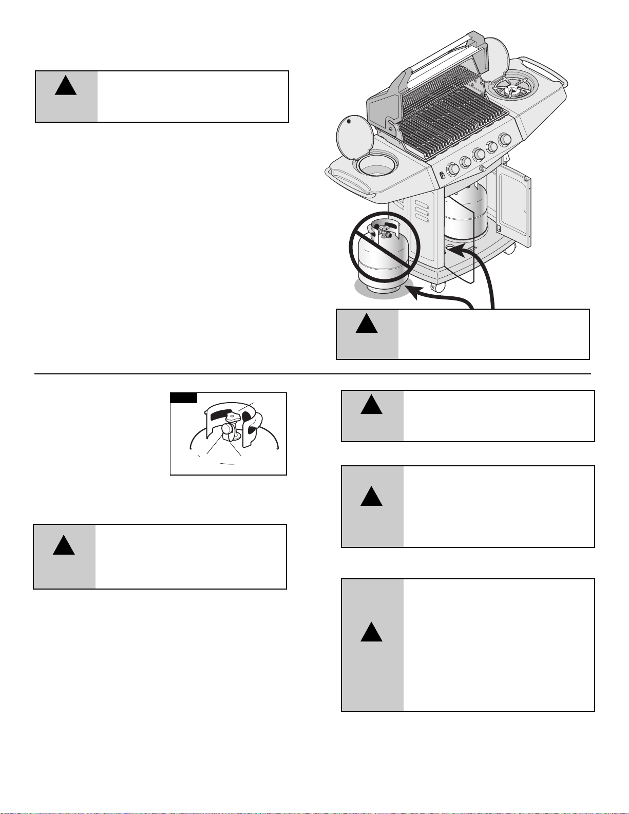
DO NOTstore a spare L.P. (propane) cylinder under or near your barbeque.
• DO NOTleave your barbeque unattended while in operation.
• DO NOTallow children to operate or play near your barbeque.
• DO NOTuse while under the influence of alcohol or drugs.
• DO NOTinstall/use in or on recreational vehicles and/or boats
WARNING
!
DO NOT USE CHARCOAL OR
CERAMIC BRIQUETS IN
THIS GAS GRILL, THEY ARE NOT
REQUIRED.
If the above instructions are not followed
exactl
y, a fire causing death or serious
inju
ry may occur.
• Keep the ventilation opening(s) of the cylinder enclosure free and
clear from debris.
Page 3
BEFORE YOU USE
THIS APPLIANCE
• Your barbeque is properly assembled.
• There are no leaks in the gas supply system (see 'Leak Testing
section)
.
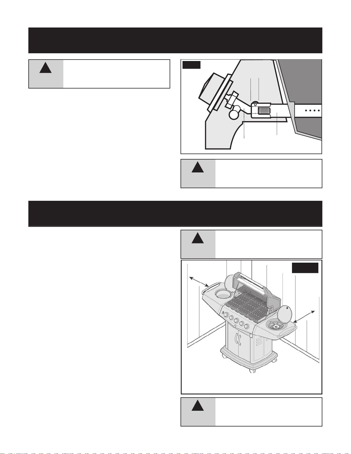
• The burner is properly assembled with the venturi tubes seated
over
the valve outlets (Figure 1 below) and there are no blockages
present
in the venturi tubes (see
Cleaning
Venturi Tubes’ Section).
• All electrical supply cords and/or gas supply hoses are kept away
from
all or any heated surfaces.
• Your barbeque is positioned in a safe location (see ‘ Installation ’
section). Figure
1.
• Ensure valve outlets (orifices) are assembled 1 cm (3/8”) into the
venturi
tubes.
• Check to see that the valve outlets and venturi tubes are parallel to
the
bottom of the base casting of your appliance.
GETTING FAMILIAR WITH YOUR BARBEQUE
CARING FOR YOUR EQUIPMENT
INSTALLATION
THE INSTALLATION OF THIS APPLIANCE MUST CONFORM WITH LOCAL
CODES
OR, IN THE ABSENCE OF LOCAL CODES:
APARTMENT DWELLERS
Check with management to learn the requirements and fire codes
for
using an LP gas grill in your apartment complex. If allowed, use
outside
on the ground floor with clearances as stated in Figure 2
from
walls or rails. Do not use on or under balconies.
VENTURI
TUBE
VALVE
CASTING
Fig. 1
DO NOT USE YOUR BARBEQUE UNTIL YOU HAVE
READ
AND UNDERSTOOD ALL THE
INFORM
ATION IN THIS MANUAL.
IT
IS EXTREMELY IMPORTANT TO BE SURE THAT:
FAILURE TO ENSURE THE ABOVE MAY RESULT
IN
A HAZARDOUS FIRE OR EXPLOSION
CAUSING
SERIOUS BODILY INJURY
AND/OR
PROPERTY DAMAGE.
61cm (24")
46cm
(18")
Fig. 2
3
10mm
MODEL MAY NOT BE
EXACT
LY AS SHOWN.
WARNING
!
WARNING
!
WARNING
!
DO NOT USE THIS GAS OUTDOOR
APPLIANCE UNDER ANY OVERHEAD
COMBUSTIBLE
CONSTRUCTION.
WHEN DECIDING WHERE TO PLACE YOUR
APPLIANCE,
FOLLOW THESE MINIMUM
CLEARANCE
DISTANCES TO ADJACENT
COMBUSTIBLE
MATERIALS:
WARNING
!
• 61 cm (24 inches)
from side of unit
(See Figure 2)
• 46 cm (18 inches)
from back of unit
(See Figure 2)
• with either the National Fuel Gas Code ANSI Z223.1/NFPA 54,
Gas and Propane Installation Code, CSA B149.1, or
Natural
Propane
for
Z240
• Handling and storage of LP cylinders must conform to LP Gas
Code
vehicles
• All electrical accessories (such as rotisserie) must be electrically
grounded
Code,
supply
• This grill is safety certified for use in the United States and
Canada
Modification
Storage and Handling Code, B149.2, or the Standard
Recreational Vehicles, ANSI A 119.2/NFPA 119.2, and CSA
RV Series, Recreational Vehicle Code, as applicable.
NFPA/ANSI 58. Grill is not for use in or on recreational
and/or boats.
in accordance with local codes, or National Electrical
ANSI/NFPA 70. Keep any electrical cords and/or fuel
hoses away from any hot surfaces.
Only. Do not modify for use in any other location.
with result in a safety hazard.
Page 4
L.P. GAS CYLINDER
Gas cylinders manufactured today have mechanisms to provide worry free
barbequing year round:
Q.C.C.1 or Type 1-Quick Connect Coupling Valve, ensure fast tank hook-ups
requiring only hand tightening. The redundant valve system inhibits the flow
of gas to the burner if the connection is not 100% correct.
O.P.D. or Overfill Protection Device prevents accidental gas leaks caused by
cylinder “over pressurization”, the leading cause of cylinder gas leaks. The
float in the tank will automatically stop filling at 80% capacity, leaving a 20%
area for the expansion of liquid. Without this safety feature, the relief valve may
open and discharge propane, creating a potential safety hazard. An O.P.D.
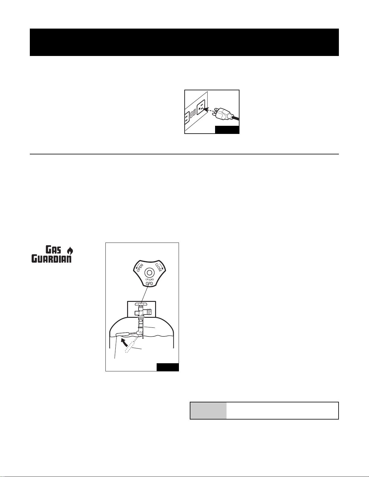
cylinder is easily distinguished by its triangular hand wheel valve. (Figure 3)
Look for the Gas Guardian symbol to
easily identify propane cylinders with
these safety features.
1. SPECIFICATIONS
Self-contained propane gas barbeque
systems are designed to be used only
with a 9.1 kg (20 lb) propane cylinder,
equipped with a Type 1 cylinder valve
and incorporating an overfill protection
device (O.P.D). This barbeque cannot
be connected to an existing #510 P.O.L.
type valve (ones with left-hand threads).
The cylinder for your gas barbeque
must be constructed and marked in
accordance with the specifications of
L.P. gas cylinders:
In Canada: The National Standards of Canada CAN/CSA-B339, Cylinders,
Spheres and Tubes for Transportation of Dangerous Goods; and Commission.
In the U.S.: U.S. Department of Transportation (D.O.T.)
DO NOT CONNECT TO A PROPANE GAS CYLINDER EXCEEDING THIS CAPACITY,
OR USE A CYLINDER WITH ANY OTHER TYPE OF VALVE CONNECTION DEVICE.
The Type 1 valve is recognizable by the large external thread on the outlet
part of the valve. Standard existing valves do not have these exterior threads.
WARNING
If the above instructions are not followed exactly,
a fire causing death or serious injury may occur.
FILLING STOPS AT
80%
NEW OPD
HANDWHEEL
Fig. 3
O.P.D.
FLOAT
SAFETY:
• Always turn off the cylinder valve tightly when your barbeque is not in use.
• Handle tank valves with care.
• Never connect an unregulated L.P. gas cylinder to your barbeque.
• Never store a spare cylinder under or near your barbeque when in use.
• Never subject any cylinder to excessive heat or direct sunlight.
• Always keep your in-use cylinder securely fastened in an upright position.
• Do not insert any foreign objects into the valve outlet. You may damage
the back-check. A damaged back-check can be the source of a leak. Leaking
propane may result in explosion, fire, severe personal injury or death.
• Never fill the cylinder beyond 80% full.
Any attempt to connect a regulator, with other than the:
i) Mating Type 1 connector (recognized by the large black coupling nut) or
ii) Standard #510 P.O.L. fitting,
by use of adapters or any other means, could result in damage, fire or injury and
may negate the important safety features designed into the Type 1 system. The
connection of a #510 P.O.L. fitting will not provide the flow control or temperature
shut-off features built into the complete Type 1 system.
We strongly recommend use of a propane cylinder with Q.C.C.I and O.P.D.
safety features.
THE CYLINDER MUST ALSO BE EQUIPPED WITH:
a. A shut-off valve terminating in a proper cylinder valve outlet specified in
current standards:
• Canada: CAN/CGA - 1.6a - M98 - Outdoor Gas Grills - Amend.
• U.S.: ANSI Z 21.58a-1998 OUTDOOR COOKING APPLIANCES.
b. A listed overfilling protection device (O.P.D.).
c. A safety relief valve having direct communication with the vapor space of
the cylinder.
d. A collar to protect the tank shut off valve.
e. An arrangement for vapor withdrawal.
f. A bottom ring for securing to tank support assembly.
THE CYLINDER SHOULD NOT EXCEED 472 MM (18 1/2") IN HEIGHT AND 317
MM (12 1/2") IN DIAMETER.
4
ELECTRICAL CAUTION
• If any accessory installed on this barbeque requires an external electrical
power source, it must be electrically grounded in accordance with local
laws or in the absence of local laws, with the Canadian Electrical Code
CSA C22.1 or in the U.S., with the National Electrical Code ANSI-NFPA 70.
• The three-prong plug provides protection against shock hazard and should
be plugged directly into a properly grounded three-prong receptacle. Do
not cut or remove the grounding prong from this plug.
• To ensure continued protection against risk of electric shock, connect to
properly earthed outlets only.
• Ensure all electrical supply cords and fuel supply hoses are kept well away
from any heated surfaces.
CARING FOR YOUR EQUIPMENT
PROVIDING POWER TO YOUR BARBEQUE
To provide power to the barbecue, plug grounded electrical cord into
rear electrical box as shown. (Fig.15)
Plug electrical cord into properly grounded
GFI (Ground Fault Interrupt) receptacle. If
use of an extension cord is required, be
sure that it is a minimum 16 AWG,
3 wire well insulated cord, marked
for OUTDOOR USE ONLY and properly
grounded. (Fig.14)
CAUTION: To ensure continued protection against risk of
electric shock, connect to properly earthed outlets only.
Fig. 14
TM
Page 5
WARNING
!
TRANSPORTATION AND STORAGE:
PROPANE GAS IS HEAVIER THAN AIR, AND WILL COLLECT IN LOW AREAS,
INCREASING THE ABOVE RISKS. THEREFORE:
• ALWAYS use the cylinder cap provided with your cylinder whenever the
cylinder is not connected to your barbeque. (Figure 4)
• DO NOT store in a building, garage or any other enclosed area. Store in a
well-ventilated area.
• DO NOT store near any gas burning apparatus or in any high-heat areas
such as a closed car or trunk.
• Transport and store the cylinder in an upright position – do not tip on its side.
• Store out of reach of children.
• DO NOT smoke while transporting a cylinder in your vehicle.
WARNING
• Never fill a cylinder beyond 80% full.
• An over filled or improperly stored cylinder is a hazard
due to possible gas release from the safety relief valve.
This could cause an intense fire with risk of property
damage, serious injury or death.
• If you see, smell or hear gas escaping, immediately get
away from the LP cylinder/appliance and call your fire
department.
Although it is safe when used properly,
careless handling of the propane gas cylinder
could result in fire, explosion, and/or serious
injury.
FILLING:
FOR SAFETY REASONS, IF AN OPTIONAL
L.P. GAS CYLINDER WAS SUPPLIED
WITH YOUR BARBEQUE, IT HAS BEEN
SHIPPED EMPTY. THE CYLINDER MUST
BE PURGED OF AIR AND FILLED PRIOR
TO USING ON YOUR BARBEQUE. WHEN
GETTING YOUR CYLINDER FILLED:
• Allow only a qualified L.P. gas dealer to fill or repair your cylinder.
• DO NOT allow the cylinder to be filled beyond 80% full.
• Make sure the L.P. gas dealer checks the cylinder for leaks after filling.
LP CYLINDER EXCHANGE
Many retailers that sell grills offer you the option of replacing your
empty LP cylinder through an exchange service. Use only those
reputable exchange companies that inspect, precision fill, test and
certify their cylinders. Exchange your cylinder only for an OPD safety
feature-equipped cylinder as described in the "LP Cylinder" section of
this manual.
• Always keep new and exchanged LP cylinders in upright position
during use, transit or storage.
• Leak test new and exchanged LP cylinders BEFORE connecting
to grill.
CYLINDER
CAP
RETAINER
STRAP
LP TANK
VALVE
Fig. 4
5
WARNING
!
DANGER
NEVER STORE A SPARE LP CYLINDER
UNDER OR NEAR THE APPLIANCE OR
IN AN ENCLOSED AREA.
!
Never operate grill with LP cylinder
out of correct position specified in
assembly instructions.
WARNING
!
Always close LP cylinder valve and
remove coupling nut before moving
LP cylinder from specified
operation position.
DANGER
!
Do not insert any tool or foreign
object into the valve outlet or safety
relief valve. You may damage the
valve and cause a leak. Leaking
propane may result in explosion, fire,
severe personal injury, or death.
WARNING
!
• Never attempt to attach this grill to
the self-contained LP gas system of
a camper trailer or motor home.
• Do not use grill until leak-tested.
• If a leak is detected at any time,
STOP and call the fire department.
• If you cannot stop a gas leak,
immediately close LPcylinder valve
and call LP gas supplier or your fire
department!
Page 6
6
NOTE: IMPROPER LIGHTING PROCEDURES CAN CAUSE THE FLOW CONTROL
TO ACTIVATE, RESULTING IN REDUCED HEAT OUTPUT. IF THIS IS SUSPECTED,
RESET THE FLOW CONTROL BY SHUTTING OFF ALL BURNER CONTROLS AND
THE CYLINDER VALVE. WAIT 30 SECONDS, THEN TURN THE CYLINDER VALVE
ON EXTREMELY SLOWLY - WAIT 5 SECONDS AND TURN THE BURNER VALVE
ON AND LIGHT AS NORMAL.
• Never connect a propane gas barbeque to an unregulated propane gas
supply or any other gas. Do not attempt to alter the hose or regulator in
any way.
• The connection fitting must be protected when disconnected from the
propane tank. If the fitting is allowed to drag on the ground, nicks and
scratches could occur resulting in a leak when connected to the propane tank.
PROPANE AND NATURAL GAS MODELS:
• Do not allow any grease (or other hot material) to fall onto the hose, or
allow the hose to come in contact with any hot surfaces of the barbeque.
• Visually inspect the entire length of the hose assembly before each use
of the barbeque. If it is evident there is excessive abrasion/wear, or the
hose is cut, it must be replaced prior to using your barbeque. Only the
hose assembly as specified in the Parts List should be used.
• Follow the ‘LEAK TEST’ instructions before lighting your barbeque for
the first time, every time a propane cylinder is refilled, if any gas
component is changed, if the regulator flow-limiting device has been
activated, after prolonged periods of storage or non-use or at least once
per season.
NATURAL GAS MODELS:
• Never use with propane, or any other gases.
• The appliance and its individual shut-off valve must be
disconnected from the gas supply piping during any pressure
testing of the system at test pressure in excess of 3.5 kPa (1/2
p.s.i.).
• The appliance must be isolated from the gas supply piping
system by closing its individual manual shut-off valve during
any pressure testing of the gas supply piping system at
pressures equal to or less than 3.5 kPa (1/2 p.s.i.).
• The gas supply hose must be a minimum of 3.1 m (10 ft) and a
maximum of 3.6 m (12 ft). Always disconnect hose at quick
connect coupling when storing your barbeque.
• Inspect and clean quick connect coupling, and keep it protected
when it’s not in use.
HOSE & REGULATOR
PROPANE GAS MODELS:
Your barbeque is designed to operate on L.P. (propane) gas at a pressure
regulated at 2.74 kPa (11" water column). A regulator preset to this pressure
is supplied with the barbeque and MUST be used.
This regulator is equipped with the Q.C.C. Type 1, quick connect coupling
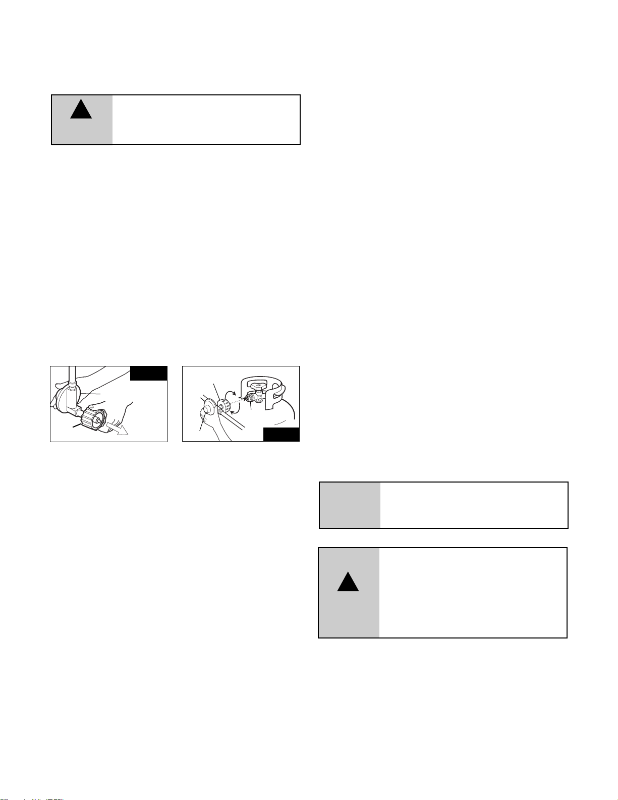
system, which incorporates the following safety features: (Figure 5)
• It will not allow gas to flow until a positive seal has been made (Figure 6)
• It has a thermal element that will shut off the flow of gas between
115 and 150°C (240 and 300°F)
• It also has a flow-limiting device which, when activated, will restrict the flow
of gas to 0.28 cubic metres per hour (10 cubic feet per hour)
Prior to attaching the propane cylinder to the hose and regulator, be sure the
cylinder valve and the appliance valves are OFF. The cylinder valve is turned
off by rotating the handwheel (see Figure 3) clockwise (left to right) until it
stops and all appliance valves should be in the twelve o'clock position. When
attaching the regulator to the cylinder, make sure that the small probe in the
nipple is centered in the mating Q.C.C. 1 cylinder valve (see Figure 6). Turn the
right hand threaded Q.C.C.1 black nut onto the valve in a clockwise motion until
there is a positive stop.
DO NOT USE A WRENCH, HAND TIGHTEN ONLY.
Should the large black thermally sensitive coupling nut be exposed to temperatures
above 115 - 150°C, it will soften and allow the regulator probe to disengage
from the cylinder valve – thereby shutting off the flow of gas. Should this occur,
do not attempt to reconnect the nut. Remove the entire regulator assembly,
and replace it with a new one.
The cause of the excessive heat should be determined and corrected
before operating your barbeque again. The regulator probe also contains a
flow-sensing element, which will limit the flow of gas to the regulator to a
manageable amount (0.28 cubic metres/hour) in the event of a hose or
regulator rupture. If it is evident that the flow control device has been
activated, the cause of the excessive flow should be determined and corrected
before using your barbeque again.
WARNING
FAILURE TO ENSURE THE ABOVE MAY RESULT
IN A HAZARDOUS FIRE OR EXPLOSION
CAUSING SERIOUS BODILY INJURY AND/OR
PROPERTY DAMAGE.
WARNING
WARNING: INDICATES AN POTENTIALLY
HAZARDOUS SITUATION WHICH, IF NOT AVOIDED,
COULD RESULT IN DEATH OR SERIOUS INJURY.
!
Fig. 5
Fig. 6
REGULATOR
REGULATOR
STRAIGHT
Q.C.C.I
Q.C.C.I
WARNING
DO NOT ATTEMPT TO REPAIR OR ALTER THE
HOSE/VALVE/REGULATOR FOR ANY "ASSUMED"
DEFECT. ANY MODIFICATION TO THIS ASSEMBLY
WILL VOID YOUR WARRANTY AND CREATE THE
RISK OF A GAS LEAK AND FIRE. USE ONLY
AUTHORIZED REPLACEMENT PARTS SUPPLIED BY
MANUFACTURER.
!
Page 7
7
Fig. 7C
STANDARD
3 BURNER
Fig. 7D
GAS VALVE
3 BURNER WITH SIDE
BURNER & ROTISSERIE
HOSE &
CONNECTIONS
SIDE BURNER
GAS LINE
REGULATOR
GAS VALVE
GAS REGULATOR
EXTERNAL
THREAD
HAND
VALV E
Fig. 7B
THERMALLY
SENSITIVE
NUT
PROBE
TANK
TANK
WELDS
Fig. 7A
CLEANING VENTURI TUBES
Periodic cleaning of the venturi tubes is recommended
for optimum burner performance, especially after
prolonged storage or a period of non-use.
How to Clean:
• Remove the burner (refer to ‘ASSEMBLY PROCEDURE’).
• Use a venturi cleaning brush and insert the brush into the venturi tube 1
inch at a time, then remove to prevent moving the debris upwards
(see Figure 8).
• As you remove the brush head inspect and discard any debris
• Continue this procedure until the entire lengths of all venturi tubes are
free of debris.
• Reinstall burner (as per assembly instructions), ensure the venturi
tubes are seated over the valve orifices (see Figure 1).
• Perform a Leak Test (see pages 4 & 5).
CHECK TO ENSURE THE BURNER HAS A
GOOD FLAME EACH TIME IT IS TURNED ON.
Fig. 8
VALVE
BLOCKAGE
VENTURI
CLEANING BRUSH
WARNING
It is possible that very small insects could make webs or nest in the venturi tubes, as they are naturally
attracted to the smell of gas. This will partially or completely block the flow of gas through the venturi
and is indicated by a smoky yellow flame, and/or a burner that is difficult or impossible to light.
Ultimately, it may cause the gas to burn outside the venturis, which can cause a fire resulting in
damage to your barbeque and potential personal injury. IF THIS HAPPENS IMMEDIATELY SHUT OFF THE PROPANE AT
CYLINDER. When the barbeque has cooled, follow the "How to Clean" steps above.
WARNING
Failure to ensure the above may result in a
hazardous fire or explosion causing serious
bodily injury and/or property damage.
REGULATOR
HOSE &
CONNECTIONS
To keep your barbeque working at its peak efficiency
as well as contribute to the safe operation of this
unit, perform all of the operations below at least
once a year -- preferably at the start of each cooking
season.
PERFORM A LEAK TEST
A leak test ensures that there are no gas leaks prior to lighting your
barbeque.
WHEN A LEAK TEST MUST BE PERFORMED:
• Before lighting your barbeque for the first time
• Every time the propane cylinder is refilled
• If any gas component is changed
• At a minimum once per season
• After prolonged period of storage or non-us
• If the regulator flow-limiting device has been activated
The leak test should be performed in a well-ventilated area away from any
open flame, heat or ignition sources.
DO NOT USE A MATCH, OPEN FLAME OR SMOKE DURING LEAK TESTING.
WHAT YOU’LL NEED FOR TESTING:
1. A mixture of 50% liquid dish soap and 50% water.
2. A brush or cloth to apply the mixture.
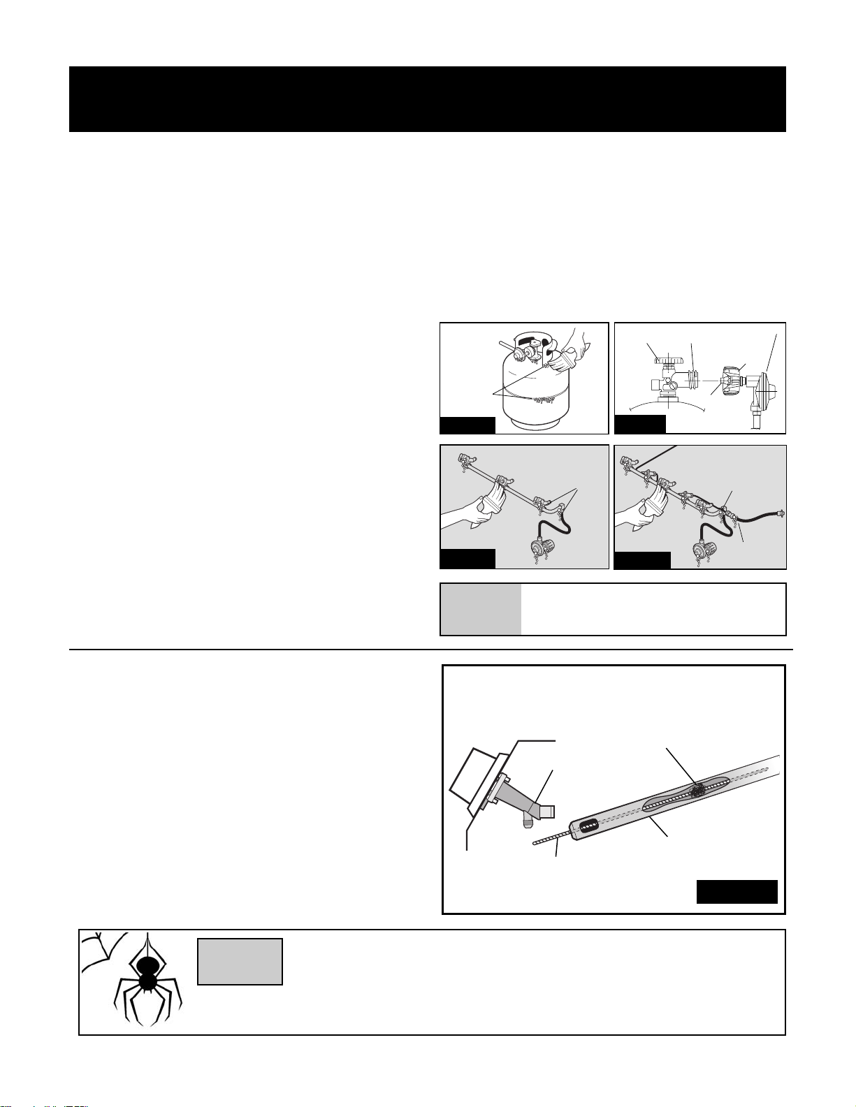
AREAS TO TEST ON A PROPANE BARBEQUE:
• All propane cylinder welds (see Figure 7A)
• Propane cylinder valve – including threads into cylinder (see Figure 7B)
• Regulator fitting and propane cylinder connection (see Figure 7B)
• All hose connections (see Figure 7C) including side burner tubing,
if equipped (see Figure 7D)
• All valve connections (see Figure 7C & D)
AREAS TO TEST ON NATURAL GAS BARBEQUES:
• All hose connections (see Figure 7C)
• All valve connections (see Figure 7C & 7D)
CLEANING & MAINTENANCE
HOW TO DO THE TESTING:
1. With the barbeque console control knobs in the ‘OFF’ position, twist the valve
on your propane cylinder 1 turn, or the main natural gas valve on.
DO NOT IGNITE THE BURNERS WHILE PERFORMING THE LEAK CHECK.
2. Brush your soap and water solution on all connections and components
as outlined above.
3. Observe each place for growing bubbles, which indicate that a leak is present.
4. Shut off the flow of gas while fixing the leak. Tighten any leaking
connection and repeat test until no leaks are detected.
5. If the leak(s) cannot be stopped DO NOT USE. Shut off the fuel source at
the valve immediately (if appropriate, remove propane cylinder). Call a
certified gas appliance service person, or a gas dealer for proper repairs.
Page 8
CLEANING OTHER PARTS OF
YOUR APPLIANCE
General Grill Cleaning: Do not mistake brown or black accumulation
of grease and smoke for paint. Interiors of gas grills are not painted
at the factory (and should never be painted). Apply a strong solution
of detergent and water or use a grill cleaner with scrub brush on
insides of grill lid and bottom. Rinse and allow to completely air dry.
Do not apply a caustic grill/oven cleaner to painted surfaces.
BURNER:
At least twice a year, clean your burner when cleaning the venturi tubes. The
burner can be gently scraped clean with a brass bristle brush. Ensure that all
burner ports (openings) are clear (DO NOT ENLARGE BURNER PORTS). If you
find cracks, abnormal holes, or damage caused by corrosion during your
inspection and cleaning, replace burner. (SEE WARRANTY).
IGNITOR:
Clean the ignitor clip lightly using a wire brush to remove rust and grease.
DO NOT USE WATER OR CLEAN THE ELECTRODE WITH THE WIRE BRUSH.
Visually inspect the ceramic of the electrode for cracks. The electrode can be
wiped with a soft cloth if necessary. If a crack is found, a replacement ignitor
system will be required.
CLEANING GRIDS:
After each use, scrub the cooking grids with a stiff long-handled brass brush. Do
not use steel brushes, as they can scratch the nickel or porcelain coating. Grids
can also be washed with mild detergent. Never use commercial oven cleaners.
If rust appears on your cooking grids, remove the rust with a scrub pad and
coat the grid with some cooking oil. If excessive wear is evident, you might
want to replace or upgrade your cooking grid.
PORCELAIN SURFACES:
Because of glass-like composition, most residue can be wiped away with baking
soda/water solution or specially formulated cleaner. Use nonabrasive scouring
powder for stubborn stains.
PAINTED SURFACES:
Wash with mild detergent or nonabrasive cleaner and warm soapy water. Wipe
dry with a soft nonabrasive cloth.
STAINLESS STEEL SURFACES:
To maintain your grill's high quality appearance, wash with mild detergent and
warm soapy water and wipe dry with a soft cloth after each use. Baked-on grease
deposits may require the use of an abrasive plastic cleaning pad. Use only in
direction of brushed finish to avoid damage. Do not use abrasive pad on areas
with graphics.
SIDE SHELVES:
Metal Shelves: Use any household cleaner, except those containing acid or
mineral spirits. Be sure to rinse well after cleaning.
DO NOT USE AS A CUTTING BOARD.
Plastic Shelves: Wash with warm soapy water and wipe dry. A Do not use
citrisol, abrasive cleaners, degreasers or a concentrated grill cleaner on
plastic parts. Damage to and failure of parts can result.
PLASTIC PARTS:
Wash with warm soapy water and wipe dry. A Do not use citrisol, abrasive
cleaners, degreasers or a concentrated grill cleaner on plastic parts. Damage
to and failure of parts can result.
8
CASTING INTERIOR AND WARMING RACK:
At least once a year remove all components from inside your barbeque.
Loosen any cooking residue with a scraping tool for large particles and a
brass barbeque brush for smaller particles. Scrub with hot water and a
strong detergent, then rinse thoroughly or spray barbeque degreaser liberally
on all interior surfaces. Be sure to use gloves and eye protection. Let stand
for 10 minutes, scrape off residue and repeat if required. Rinse thoroughly
with water. Replace all components as outlined in the assembly instructions.
DO NOT USE DEGREASER ON PAINTED OR PLASTIC SURFACES.
DO NOT ALLOW EXCESSIVE GREASE OR OTHER RESIDUE TO BUILD UP ON
YOUR COOKING SYSTEM AS A FIRE MAY RESULT.
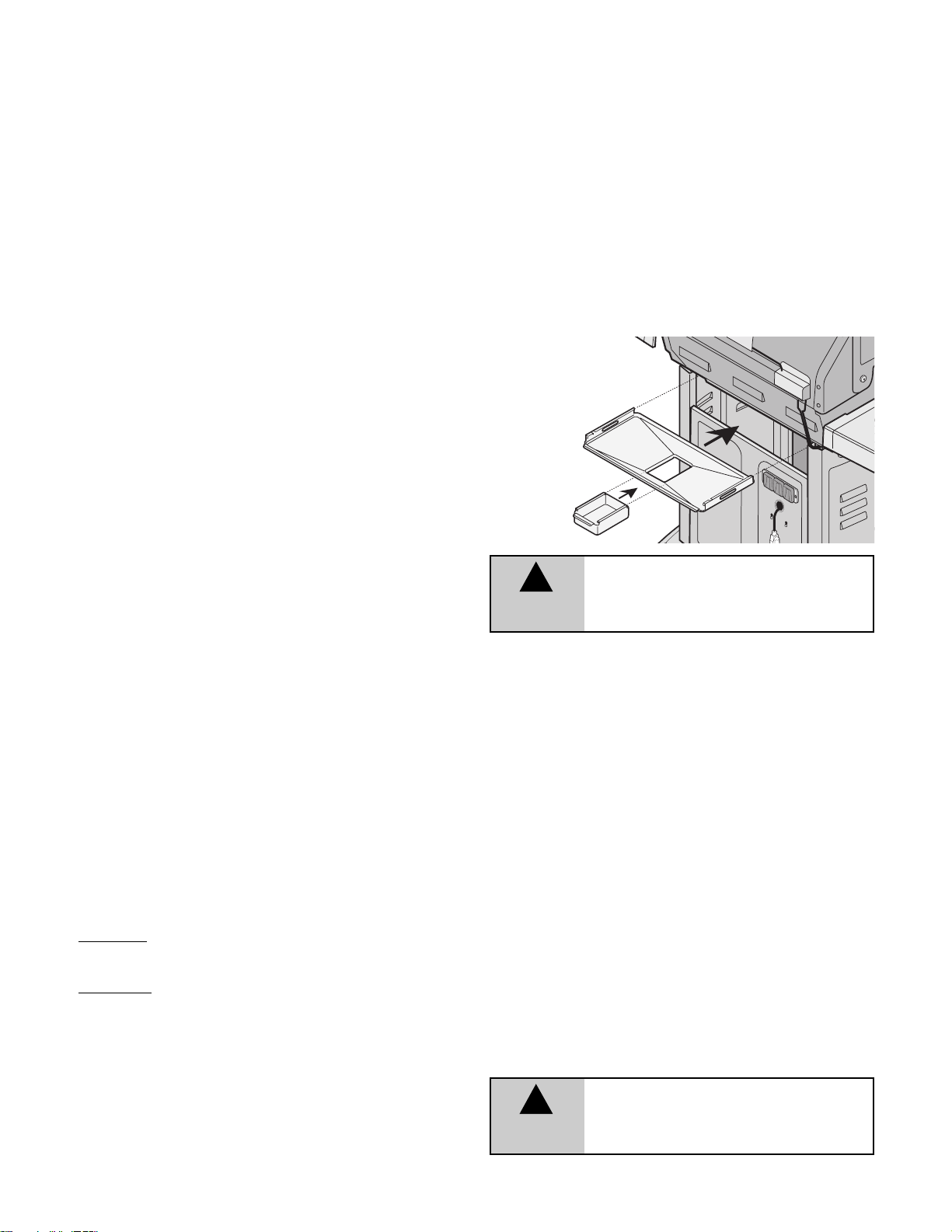
GREASE CUP HOLDER: The grease cup holder is located on the
bottom of the base casting, immediately below the hole through which any
grease will drain. The grease cup should be checked and replaced regularly to
prevent grease from overflowing.
COVER YOUR BARBEQUE WHEN IT IS NOT IN USE TO PROTECT THE SHELVES
FROM THE OUTDOOR ELEMENTS.
STORAGE
More people are discovering the pleasure of year round barbequing. However, if
you choose to store your barbeque for the winter or any extended length of time,
follow these steps:
• Clean the cooking grids, then oil lightly with cooking oil, wrap in paper and
then store the cooking grids indoors.
• Follow the same cleaning method above for the burners and any warming
racks.
• Cover the barbeque if it is left outdoors.
• When the barbeque is not in use, the gas must be turned off at the L.P.
cylinder valve or main shut off valve, and stored outdoors in a
well-ventilated area.
1. With a Propane appliance you can store the barbeque inside, PROVIDED
the cylinder is removed from the barbeque and stored outdoors in a
well-ventilated area, out of the reach of children. When the cylinder is
disconnected from the barbeque, ensure the cylinder valve safety cap is firmly
threaded through onto the valve.
2. With a Natural Gas appliance, the gas must be turned off at the individual
gas shut off valve and the hose must be disconnected from the gas supply
piping system before storing the barbeque indoors. Install plastic covers
to quick connect fittings.
After a period of storage or non-use a leak test should be performed and the
burner venturis cleaned prior to use.
Ensure grease
trap and cup are in
position and clean
before using
the BBQ.
WARNING
!
Ensure that grease trap and cup are emptied
after each use. If excess grease is allowed to
accumulate, a possible fire causing property
damage or serious injury may occur.
DANGER
NEVER STORE A SPARE LP CYLINDER
UNDER OR NEAR THE APPLIANCE OR
IN AN ENCLOSED AREA.
!
Page 9
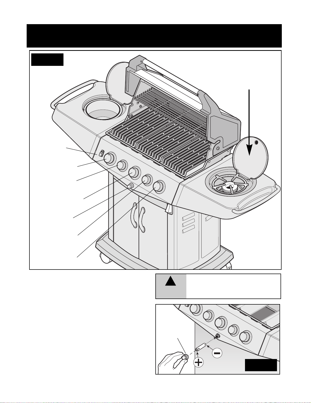
USING YOUR APPLIANCE CORRECTLY
LEFT BURNER
RIGHT BURNER
IGNITOR
*SIDE BURNER
(READ WARNING)
Fig. 9A
9
GETTING FAMILIAR
WITH THE CONTROLS
Prior to lighting your barbeque, ensure you become Familiar
with the controls (see above).
On barbeques with triple controls, the large right control knob
operates the right burner, the large middle control knob
operates the middle burner and the large left control knob
operates the left burner. (Figure 9A)
If equipped with optional side burner and rotisserie burners,
the right small knob operates the side burner, and the small
left knob operates the rotisserie. (Figure 9A)
IGNITOR BATTERY
Ensure AA BATTERY is installed correctly, put - (negative)
side of battery in first. (Fig. 9B)
CENTER BURNER
*ROTISSERIE
BURNER
WARNING
!
DO NOT LIGHT SIDE BURNER WITH LID DOWN.
FAILURE TO DO SO MAY CAUSE SERIOUS BODILY
INJURY AND/OR PROPERTY DAMAGE.
WARNING: ENSURE
SIDE BURNER LID IS
UP BEFORE LIGHTING
SIDE BURNER.
*INTERNAL
LIGHT
MODEL MAY NOT BE
EXACTLY AS SHOWN.
*
PARTS OPTIONAL
DEPENDING ON
MODEL PURCHASED
BATTERY
Fig. 9B
IGNITOR
CAP
E
L
I
P
AA
•
Y
R
E
T
T
A
B
Page 10
10
LIGHTING
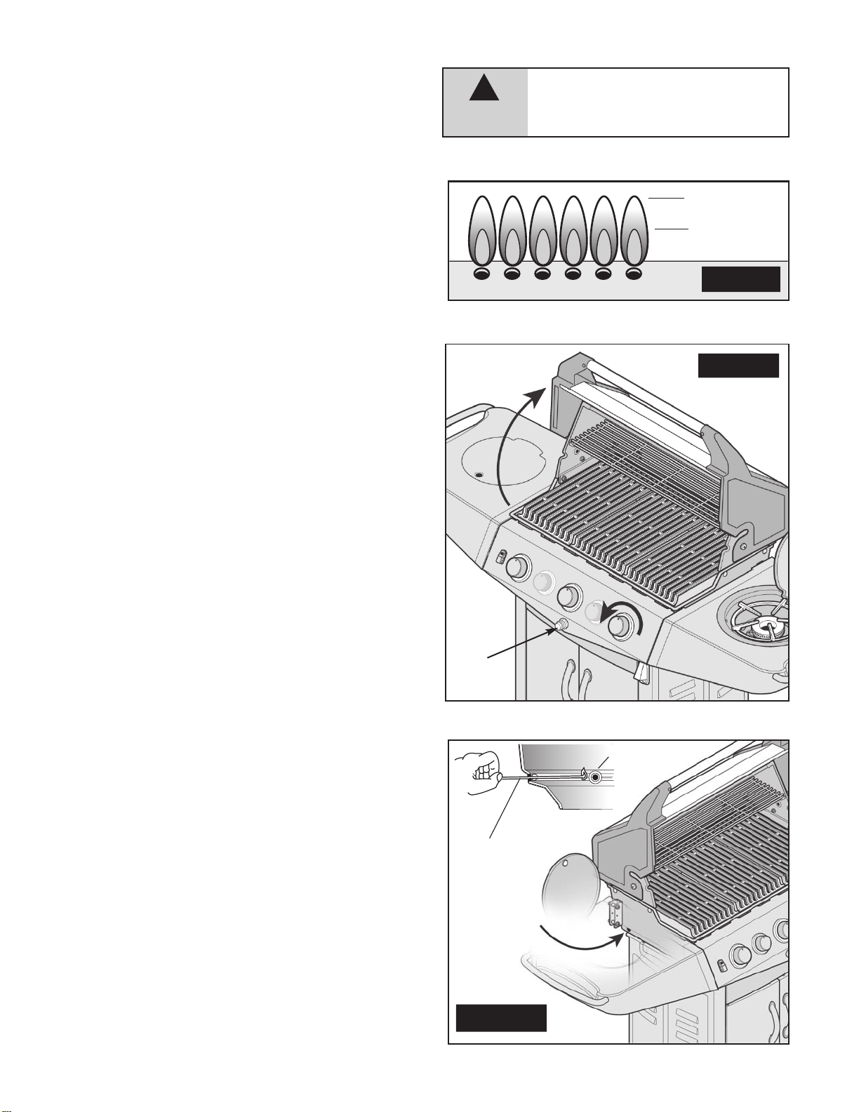
Prior to lighting your barbeque,visually check all hoses before each
use
for nicks, cracking, abrasions or cuts. If the hose is found to be
damaged
in any way, DO NOT USE YOUR BARBEQUE . A
replacement
hose and regulator is required (see ‘
PARTS LIST’ in
Assembly
Brochure).
IMPORTANT
• Always raise the barbeque lid before lighting.
• Do not lean over the barbeque when lighting the burner.
• Visually check the flames every time you light your barbeque
(Figure
10). If the flame is abnormally small or a smoky yellow --
shut
off the barbeque and check the venturi tubes for blockage
(see
Figure 8) or refer to the Troubleshooting Guide.
MAIN BURNERS
USING THE IGNITOR (Figure 11A)
1.Open the lid before lighting.
2.Turn off all of the burner control knobs and close the gas supply valve.
3.Open the gas supply valve and wait 5 seconds.
4.Push in and turn a single main burner control knob to ‘HIGH’.
All
other control knobs should be in the "OFF" position.
5.Depress
the ignitor, repeat if necessary.
6.If the burner does not light immediately (within five seconds), turn
burner
control knob off and wait 5 minutes to clear the gas.
7.Repeat steps 1 to 6. If burner still fails to light, refer to
Troubleshooting Guide to determine cause and solution, or try the
Match
Lighting procedure (Fig. 11B).
CAUTION
!
IF LIGHTING MAIN BURNERS ONLY,
ENSURE
SIDE BURNER KNOB IS IN THE OFF
POSITION.
MATCH LIGHTING PROCEDURE
1. Open the lid before lighting.
2.
Place an ignited lighter or lit match through the lighting hole,
approx.
1.25 cm (1/2") from burner. (See Figure 11B)
3. Push in and turn the left burner control knob to ‘HIGH’. The
burner
should light immediately (within five seconds). If it
does
not, extinguish the lighter or match, turn the control knob
to
off, and wait 5 minutes to clear the gas.
4.
Repeat steps 1 to 3. If burner fails to light, refer to the
Troubleshooting Guide to determine cause and solution.
5.
Once left hand burner is lit, light remaining burners in this
sequence:
center burner, then right burner.
1.
Fig. 11A
Fig. 11B
HIGH
LOW
Fig. 10
LIGHTING THE OTHER MAIN BURNERS
Once one burner has been lit, push in and turn the adjacent control
knob
to ‘HIGH’. The unlit burner will light automatically.
4.
5.
BURNER
MATCH
MATCH
LIGHTING
HOLE
LIGHTING THE OTHER MAIN BURNERS
Once one burner has been lit, push in and turn the adjacent control
knob
to ‘HIGH’. The unlit burner will light automatically.
Page 11
11
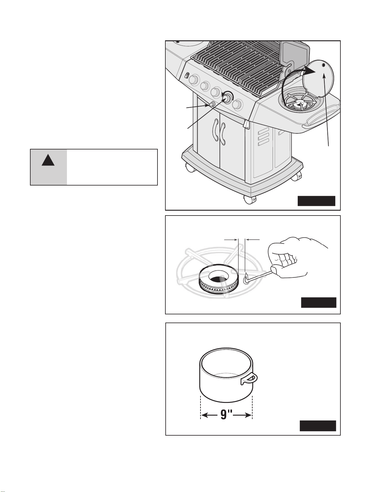
SIDE BURNER MATCH
LIGHTING PROCEDURE
1. Raise side burner lid.
2. Place an ignited lighter or lit matchnear the ports,
approximately
1/2" (1.25 cm) from burner (see
Figure
12B).
3. Push in and turn the side burner control knob to
'HIGH'.
The burnershould light immediately (within
five
seconds). If it does not, extinguish the lighter or
match,
turn the control knob off, and wait
5 minutes for the gas to clear.
4. Repeat steps 1 and 3. If burner still fails to light, refer
to
the Troubleshootin
g Guide to determine the cause
and
solution.
SIDE BURNER
COOKING POTS
1. Ensure pot size is a maximum size of
9 inches wide only.
2. Maximum weight to be used on side burner
should
not exceed 10lbs (4.5 kg)
1/2"
Fig. 12B
SIDE BURNER
(OPTIONAL)
USING THE IGNITOR
1. Raise side burner lid.
2.
Push in and turn the side burner control
knob
to 'HIGH'.
3.
Depress ignitor. Repeat if necessary (see Figure 12A).
4.
If burner does not light immediately (within five
seconds),
turn the burner control knob off, and wait 5
minutes
to clear the gas.
5.
Repeat steps 1 to 4. If burner still fails to light, refer to
the
Troubleshooting Guide to determine cause and
solution,
or try the match lighting procedure below.
3.
Fig. 12A
1.
NOTE: WHEN USING THE SIDE BURNER, THE
MAXIMUM POT SIZE IS 9" WIDE.
Fig. 12C
2.
WARNING
!
DO NOT LIGHT SIDE BURNER WITH LID
DOWN.
FAILURE TO DO SO MAY CAUSE
SERIOUS
BODILY INJURY AND/OR
PROPE
RTY DAMAGE.
NOTE: MAXIMUM
WEIGHT FOR SIDE
BURNER
10 lb (4.5 kg)
MAX
Page 12
PROPANE MODELS ONLY
If the heat output from the burner(s) seem abnormally low, it may be caused
by the regulator flow-limiting device being activated by a leak in the gas
system, or improper lighting procedures. If this is suspected, shut off the
cylinder valve and all burner valves. Perform a leak test to determine if a leak
has caused the flow-limiting device to activate. If the leak test is negative,
then carefully follow the lighting procedures step-by-step, ensuring all valves
(including tank) are off before starting.
RELIGHTING
SAFETY WARNING
If the burner flame goes out when your barbeque is in operation,
immediatelyturn
off the control valves. Wait five minutes for the gas to
clear
before attemptingto relight the burner. If the problem persists,
refer
to the Troubleshooting Guide.
SHUTTING DOWN
YOUR BARBEQUE
1. Shut off L.P. cylinder valve.
2.
Shut off burner control valves.
This
sequence prevents residual gas from being left in the system
under
pressure.
12
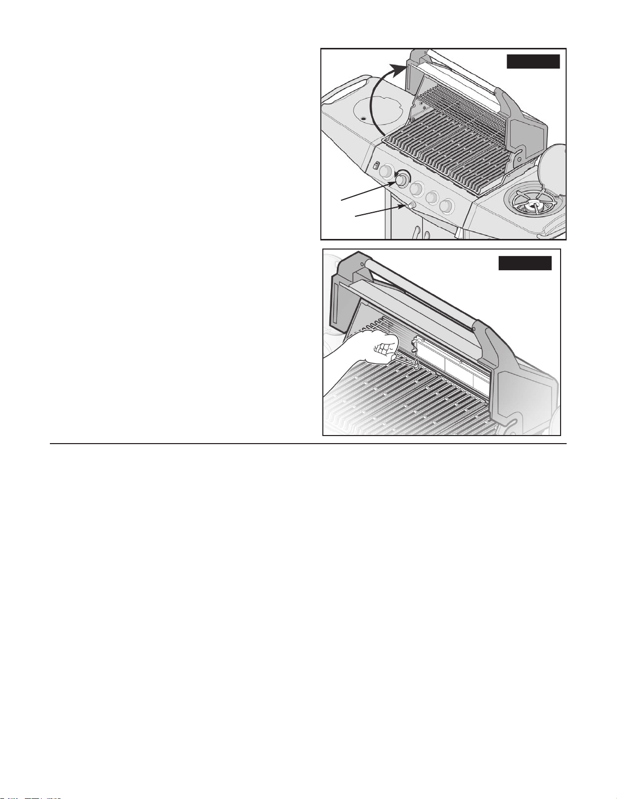
REAR ROTISSERIE BURNER
MATCH LIGHTING PROCEDURE
1. Open lid prior to lighting.
2. Place an ignited lighter or lit match near the ports, approximately
1/2"
(1.25 cm) from burner (see Figure 12D).
3. Push in and turn the rotisserie burner control knob to 'HIGH'.
The
burner should light immediately (within five seconds). If it
does
not turn off the control knob, extinguish the lighter or
match,
and wait 5 minutes for gas to clear.
4. Repeat steps 1 to 4. If burner still fails to light, refer to the
Troubleshooting Guide to determine the cause and solution.
NOTE: DO NOT USE THE MAIN BURNERS
WHEN
THE ROTISSERIE BURNER IS LIT.
Fig. 12D
REAR ROTISSERIE
BURNER
(OPTIONAL)
USING THE IGNITOR
1. Open the lid before lighting.
2.
Push in and turn the rotisserie control knob to 'HIGH'.
3.
Depress ignitor. Repeat if necessary (see Figure 12C).
4.
If burner does not light immediately (within five seconds), turn
the
burner control knob off, and wait 5 minutes to clear the gas.
5.
Repeat steps 1 to 4. If burner still fails to light, refer to the
Troubleshooting Guide to determine cause and solution,
or
try the match lighting procedure below.
2.
Fig. 12C
1.
3.
BREAKING IN YOUR BARBEQUE
Before cooking on your gas barbeque
for
the first time...
Before cooking on your gas barbeque for the first time, you should
"break
it in" by operating it for a short period of time without any
food.
To "break in" your barbeque light the barbeque following the
lighting
instructions as outlined on the console or in this manual.
(see
pages 10, 11 & 12)
BREAKING
IN THE MAIN BURNERS:
Close
the
MAIN CASTING LID ONLY
and keep the temperature
on
"HIGH" for 20 minutes.
DO NOT OPEN THE LID DURING
THIS PROCESS.
Then
raise the lid and continue to operate your barbeque on "HIGH"
for
an additional 5 minutes. Your barbeque is now ready for cooking.
BREAKING
IN THE SIDE BURNER:
To "break in" your side burner light the burner following the lighting
instruction
s as outlined in this manual. (see page 11) Keep the
temperature
on "HIGH" for 20 minutes. Your side burner is now
ready
for cooking.
CAUTION:
DO NOT CLOSE THE SIDE BURNER LID
DURING OR AFTER THE BREAK IN PERIOD WHILE
SIDE BURNER IS LIT. THE SIDE BURNER LID SHOULD
ALWAYS BE OPEN WHILE SIDE BURNER IS LIT.
Page 13
COOKING TECHNIQUES
PREHEATING THE BARBEQUE
The cooking system and grids require heating prior to adding food.
1.Light your barbeque as outlined in the ‘LIGHTING’ instruction section.
2.Once lit, preheat your barbeque on the HIGH setting with the lid down
for 6 to 10 minutes.
NOTE: OPTIONAL SIDE BURNER DOES NOT REQUIRE TO BE PREHEATED.
NEVER OPERATE SIDE BURNER WITH SIDE BURNER LID CLOSED.
3.Turn the burner control knobs to the appropriate heat setting prior to adding
your food. Preheating your barbeque is not required when you are cooking
food using indirect cooking techniques.
MAIN CASTING LID POSITION
Although keeping the main casting lid up or down when cooking on your
barbeque is a personal preference, you will find that you will have fewer
flare-ups, and your food will cook in less time (therefore using less fuel) if
the main casting lid is down. Keep the main casting lid down when cooking
food that requires a long cooking period over a low flame, such as indirect
cooking.
13
COOKING TEMPERATURES
HIGH Setting: Use the HIGH setting to preheat the barbeque, sear meat such
as steak, and to burn off any cooking residue from the grids after cooking
your meal. HIGH is rarely used for extended cooking.
MEDIUM Setting: Most grilling or roasting of meat and vegetables, as well as
any baking, is best done at a medium heat.
LOW Setting: A low temperature is used when cooking lean meat or delicate
items such as fish. All smoke cooking is done at low heat.
For the best results, invest in a Meat Thermometer
BARBEQUE COOKING METHODS
Your barbeque is more than just a place to grill your burgers and hotdogs the possibilities are as endless as your imagination. But, before you start
experimenting, here are some frequently used terms that will help:
Direct Cooking is also known as grilling. This is the most popular cooking
method and involves cooking food directly over the flame, such as searing a
steak. Other good candidates for this cooking method are thin cuts of meat,
vegetables, kabobs and fillets.
Indirect Cooking means the food is cooked away from the direct flame by
placing it on the opposite side of the lit burner and allowing the heat to tumble
within the closed confines of the closed barbeque, very similar to a convection
oven. Much like your oven, you can roast and even bake, provided your
barbeque lid is closed.
WARMING RACKS
A warming rack may be included with your barbeque and provides you with
additional cooking space away from direct heat. This is useful when cooking
delicate items such as fish, boneless chicken breasts or vegetables. Warming
racks are also a great place to keep food warm that is already done so you
can serve your entire meal at the same time.
Tip: A light application of cooking oil prior to use will help to keep food from
sticking to the warming rack.
CONTROLLING FLARE-UPS
Some flare-up during grilling is desirable to create the smoke, which gives
barbequed food its unique flavor and appearance. However, excessive flare-up
can not only ruin your food, it may lead to a dangerous condition as well. By
excessively raising the temperature within your barbeque, particularly if a build
up of grease in your barbeque ignites, these flare-ups may result in an
uncontrolled grease fire.
TO MINIMIZE FLARE-UPS:
• Trim excess fat from meats before cooking
• Cook fatty meats on a low setting, or by using the indirect method as
described above
• Ensure that your cooking system is free of excess grease from previous usage
• Check that the grease drain hole is not blocked
• Cook with lid down to cut down on the flow of air
• Reduce the heat settings
Fig. 13
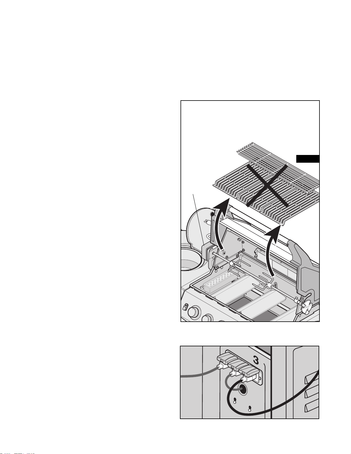
ROTISSERIE
MOTOR
LOCATION
Use of a Rotisserie motor is one of the fastest growing barbeque
cooking techniques, especially if your barbeque is equipped with a
rear rotisserie burner. Just imagine, cooking restaurant style
rotisserie meat in your own backyard! Rotisserie cooking allows the
food to self-baste while turning on the motorized spit, sealing in the
juices while browning the outside surface. Rotisserie-cooked food is
an excellent cooking option for large cuts of meat such as roasts,
leg of lamb or poultry. Fiesta Barbeque Gear Rotisseries and
Rotisserie Basket will allow you to enjoy rotisserie-cooked food on
your new Fiesta Barbeque. Locate the motor of the rotisserie on the
left side of the barbeque as illustrated in Figure 13.
To provide power to the rotisserie, plug rotisserie cord into
rear electrical box as shown (3).
CAUTION: IF USING A ROTISSERIE MOTOR, ENSURE
PARTS ARE COOL TO THE TOUCH THEN REMOVE THE MAIN
COOKING GRILLS AND WARMING RACKS. THERE IS A
CHANCE THE COOKING GRILLS COULD INTERFERE WITH THE
ROTATING FOOD AND SHOULD NOT BE INSTALLED WHILE
ROTISSERIE COOKING.
Page 14
14
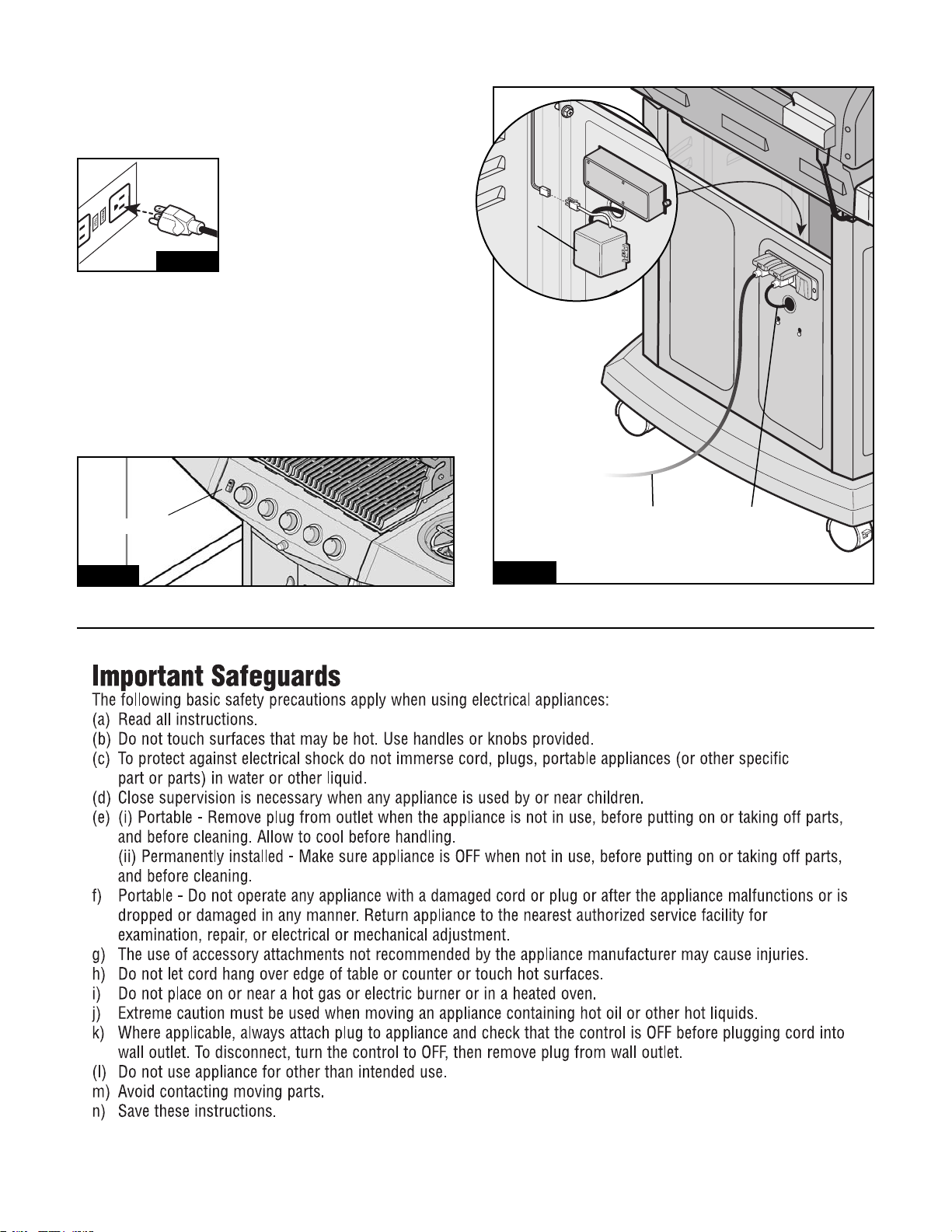
PROVIDING POWER TO YOUR BARBEQUE
To provide power to the barbecue, plug grounded electrical cord into
rear electrical box as shown. (Fig.15)
Plug electrical cord into properly grounded
GFI (Ground Fault Interrupt) receptacle. If
use of an extension cord is required, be
sure that it is a minimum 16 AWG,
3 wire well insulated cord, marked
for OUTDOOR USE ONLY and properly
grounded. (Fig.14)
CAUTION: To ensure continued protection against risk of
electric shock, connect to properly earthed outlets only.
INTERNAL LIGHT
The barbeque light allows you to cook even when it is dark. This light is preassembled and just requires to be plugged into the electrical box at the back.
Tip: To ensure light remains clean, use a damp sponge to get rid of
smoke residue before lighting grill.
ILLUMINATED SWITCH
The illuminated switch allows you to easily turn the light on and off. (Fig.16)
ILLUMINATED SWITCH
Fig. 16
TRANSFORMER
CORD
TRANSFORMER
BOX
IMPORTANT
Assemble
light switch
wires to
Internal
Transformer
box as shown.
GROUNDED
ELECTRICAL
CORD
Fig. 15
Fig. 14
Page 15

15
Burner Will Not Light (match or ignitor)
or Burners Not Hot Enough
ELECTRONIC IGNITION
• No sparks appear at any electrodes when
ignition button is pushed; no noise can be
heard from spark module.
• No sparks appear at any electrodes when
ignition switch is pushed; noise can be
heard from spark module.
• Sparks are present but not at all
electrodes and/or not at full strength
Flames Smokey Yellow
Burner Lights With Match Not With Ignitor
(no spark)
Flame Blows Out/Down Through Base
Too Much Heat/Excessive Flare-up
Persistent Grease Fire
Flames Under Heat Control Console
Regulator Humming
Incomplete Flame
Flashback...
(fire in burner tube(s)).
• Unable to fill LP cylinder.
• One burner does not light from
other burner( s).
• Sudden drop in gas flow or low flame.
• Blocked venturi tubes
• Cylinder or gas supply valve turned off
• Venturi tubes not properly seated over valve
orifices
• Burner ports blocked
PROPANE BARBEQUES ONLY
• Low or out of propane
• Flow control device activated
• Regulator not fully tightened into cylinder
• Battery not installed properly.
• Dead battery.
• Button assembly not installed properly.
• Faulty spark module.
• Output lead connections not connected.
• Output lead connections not connected.
• Arcing to grill away from burner(s).
• Weak battery.
• Electrodes are wet.
• Electrodes cracked or broken "sparks at crack".
• Partially blocked venturi tubes
• Excess cooking salts on burner
• Air shutter closed
(side burner only)
• Loose wire connection
• Broken electrode ceramic
• Poor ground
• Faulty Ignitor
• High wind conditions
PROPANE BARBEQUES ONLY
• Propane low
• Excessive fat in meat
• Grease drain plugged
• Cooking system clogged with grease
• Cooking system not positioned correctly
• Blocked venturis
PROPANE BARBEQUES ONLY
• This is not a defect or a hazard.
• Plugged, rusted, or leaking burner
• Burner and/or burner tubes are blocked.
• Some dealers have older fill nozzles
with worn threads.
• Grease buildup or food particles in
end(s) of carryover tube(s).
• Out of gas.
• Excess flow valve tripped.
• Vapor lock at coupling nut/LP cylinder
connection.
• Clean out blockage (Page 5)
• Open cylinder or gas supply valve
• Ensure proper venturi assembly (Page 2)
• Clean/replace burner (Page 5)
• Refill cylinder
• Follow correct lighting procedure (Page 6 & 7)
• Perform leak test and correct leaks (Page 4 & 5)
• Tighten regulator fully (hand tight) into cylinder
• Check battery orientation.
• Has battery been used previously? Replace Battery.
• Check to insure threads are properly engaged.
Button should travel up and down without binding.
• If no sparks are generated with new battery and good
wire connections, module is faulty.
• Are output connections on and tight?
Remove and reconnect all output connections at
module and electrodes.
• Are output connections on and tight?
Remove and reconnect all output connections at
module and electrodes.
• If possible, observe grill in dark location. Operate ignition
system and look for arcing between output wires and grill
frame. If sparks are observed other than from burner(s),
wire insulation may be damaged. Replace wires.
• All sparks present but weak or at slow rate. Replace battery
with a new AA-size alkaline battery.
• Has moisture accumulated on electrode and/or in burner ports?
Use paper towel to remove moisture.
• Inspect electrodes for cracks, if found,
replace cracked or broken electrodes.
• Clean out blockage (Page 5)
• Clean burner (Page 5)
• Open air shutter
• Check all connections are tight
• Replace
• Ensure collector box, burner and ignitor are assembled
properly.
• Relocate barbeque back towards wind
• Refill cylinder
• Trim meat/turn down burner controls and/or fuel supply
• Clean casting base and burner (Page 5 & 6)
• Clean smart bars, heat distribution plate (Page 5)
• Position cooking system correctly
• Immediately shut off gas at source, allow grill to cool and clean
out venturis (Page 5)
• Temporary condition caused by high outside temperature and
usually a full L.P. cylinder
• Clean/replace burner (Page 5)
• Turn knobs to OFF. Clean burner and/or burner tubes.
See burner cleaning section of Use and Care.
• The worn nozzles don't have enough "bite" to engage the valve.
Try a second LP dealer.
• Clean carry-over tube(s) with wire brush.
• Check for gas in LP cylinder.
• Turn off knobs, wait 30 seconds and light grill. If flames are
still low, turn off knobs and LP cylinder valve. Disconnect
regulator. Reconnect regulator and leak-test. Turn on LP
cylinder valve, wait 30 seconds and then light grill.
• Turn off knobs and LP cylinder valve. Disconnect coupling nut
from cylinder. Reconnect and retry.
TROUBLE SHOOTING GUIDE
PROBLEM POSSIBLE CAUSES CORRECTION
Page 16

16
7 YEAR PLATINUM LIMITED WARRANTY
1. LIMITED WARRANTY COVERAGE
Blue Ember gas barbeque owners have the benefit of a Platinum limited warranty from the date of purchase against any and all defects in materials and
workmanship during the period of warranty coverage specified. This limited warranty is extended to the original customer/purchaser only and is not transferable.
Your Fiesta / Blue Ember barbeque (and related equipment) have been certified for use in by the applicable certifying authorities specified on the rating
plate affixed to the barbeque and related equipment. Your Fiesta / Blue Ember barbeque must be used only in accordance with the applicable
certification and Fiesta / Blue Ember's Care and Use Instructions. It must be assembled in accordance with applicable Fiesta / Blue Ember assembly
guide. Fiesta does not recommend the conversion of the gas supply specified on the rating plate to any other fuel or equipment.
Any conversion will
result in the termination of the Fiesta Blue Ember warranty and the default of the applicable certification.
Date and proof of purchase is mandatory for all warranty claims. Always identify the product, model number and serial number when requesting warranty coverage.
This warranty covers replacement parts only. All other costs including labour, transportation postage and other incidental service costs are the
responsibility of the applicant.
The use of non Fiesta / Blue Ember replacement parts automatically voids the Fiesta Barbeque Warranty
2. LIMITATIONS
This limited warranty applies only to Blue Ember barbeques that have been properly assembled, operated and maintained and reaso nably used as defined
in the Blue Ember care and use manual, and assembly instructions. Please refer to the care and use section of this manual for instructions on the proper
care and use of your Blue Ember barbeque.
YOUR BLUE EMBER PRODUCT MUST BE USED ONLY IN ACCORDANCE WITH APPLICABLE CERTIFICATION AND FIESTA'S
CARE AND USE INSTRUCTIONS
Fiesta shall not be responsible for any indirect or consequential damages arising as a result of any defect in the barbeque whe
ther such defect is covered
by warranty or not. This limited warranty does not apply to and Fiesta Barbeques Limited shall not be responsible or liable for
any failures or operating
difficulties
caused by anything other than defective materials or workmanship.
There are no other warranties or conditions, express or implied, statutory of otherwise (including any implied warranty of merchantability or fitness for a
particular purpose) except as expressly provided for herein. No person is authorized to create for Fiesta / Blue Ember any cond
ition
or liability in
connection
with the barbeque.
Exclusions to this warranty include normal wear and tear, accidental damage, abuse, tampering or misuse, alteration, misapplica
tion,
vandalism, careless
handling,
improper installation, improper assembly, improper use, maintenance or service, deterioration or damage due to severe weather i.e. hail,
hurricanes, earthquake, tornados, or discoloration or paint chipping surface rust or rust perforation due to paint chipping res
ulting
from normal wear and
tear
or causes other than defective material or due to chemical exposure in the atmosphere, commercial or rental use, use of improper or uncertified fuel,
fuel source or equipment, or failure to do normal & routine maintenance or service, including (not limited to) removal of insec
ts
within the venturi tubes.
The
provisions of this additional written warranty are in addition to and not a modification of, nor subtraction from any other statutory warranties or other
rights and remedies provided by any provincial law. Warranty will NOT apply if this gas grill is used for commercial or rental
purposes.
The provisions of this additional written warranty are in addition to and not a modification of, nor subtraction from any other statutory warranties or other
rights and remedies provided by any provincial law. The purchaser may have different rights which may vary from province to province in Canada and
state to state in the United States of America according to applicable legislation. This warranty does not exclude or limit th
ose
statutory rights except to
the
extent permissible in law.
3. CONDITIONS FOR APPLICATION OF THE LIMITED WARRANTY
The attached limited warranty registration must be detached, filled in and returned with a copy of the purchase invoice to Fiesta Gas Grills, LLC.
One Fiesta Drive, Dickson TN, 37033 within 21 days of the date of the purchase. Alternatively, your warranty may also be registered online at fiestagasgrills.com
This limited warranty is not valid or binding unless the limited warranty is registered on line or the voucher below is completed and delivered into the
possession of Fiesta Gas Grills, LLC., within 21 days of the date of purchase. The purchaser shall retain a copy of the purchase invoice for future claims.
Purchaser must notify Fiesta Gas Grills, LLC. immediately upon discovery of any defects in the barbeque or any parts thereof for which purchaser
claims coverage under this limited warranty. All warranty service and/or replacement of Blue Ember parts must be performed by t
he
customer service
department
of Fiesta Gas Grills, LLC. Customers seeking warranty service and/or replacement should contact Fiesta customer s
ervice with their model
numbe
r, serial number and the nature of their claim. A tracking number will be issued at that time. All defective parts must be returned to Fiesta's
customer service department, accompanied by the tracking number. The purchaser shall be responsible for performance and cost of disassembly,
packaging and shipping costs. Fiesta will repair or (at it option) replace the defective components if after inspection it is evident that the defect occurred
under normal domestic use.
All warranty replacement shall be subject to the terms and conditions of this warranty for the remainder of the original period of coverage.
4. REPLACEMENT OR PRO-RATED REFUND
Fiesta / Blue Ember's undertaking under this limited warranty is:
For the first two years from the date of purchase to replace the defective part or parts.
For the remaining five years from the date of purchase to credit the prorated value of any non-electrical defective parts again
st
the purchase of
replacement
parts. In year 3, 60% of the part's value will be credited against the purchase of replacement parts, in year 4, 50% of the part's value will be
credited against the purchase of replacement parts, in year 5, 40% of the part's value will be credited against the purchase of replacement parts, in year 6,
30% of the part's value will be credited against the purchase of replacement parts, in year 7, 20% of the part's value will be credited against the purchase
of replacement parts.
If replacement parts are not available, the amount of any refund will be based upon the proportional value of the defective par
t in relation to total value of
the
barbeque at factory prices in effect in the year of the purchase and will be pro-rated for the period of time remaining und
er
the limited warranty.
The
factory prices are lower than retail selling prices and any refunds are bases upon relative value of defective part only, not entire barbeque.
When replacement parts are provided, purchaser will be charged manufacturer's approximate cost of shipping and handling replacement parts.
Re-assembly will be purchaser's responsibility.
Page 17
17
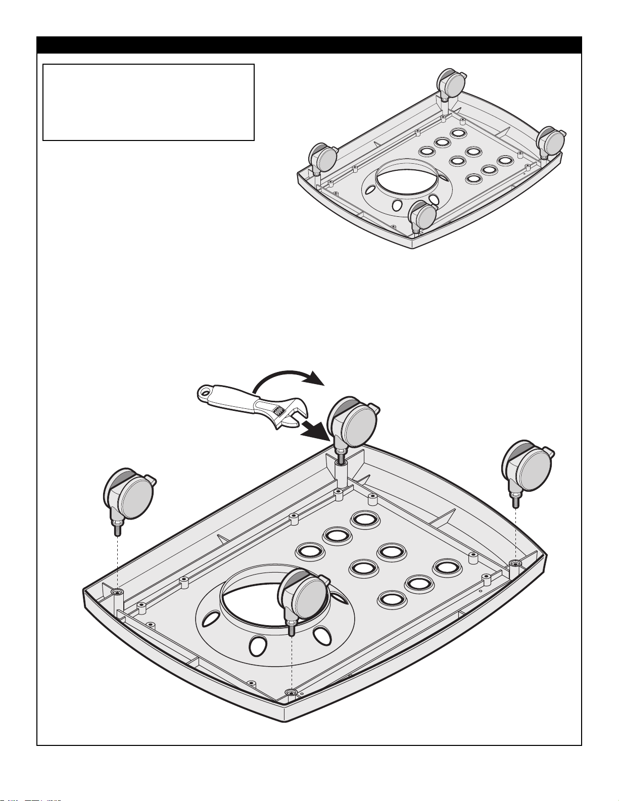
WHEEL ASSEMBLY
• Attach wheels to bottom of base as shown.
FIG.1
Assembled
View
TOOLS REQUIRED:
• Extra Common Nuts & Bolts are supplied.
• Refer to diagrams to assemble your grill.
NOTE:
Some grill parts shown in the assembly steps
may differ slightly in appearance from those
on your particular grill model. However,
the method of assembly remains the same.
Page 18
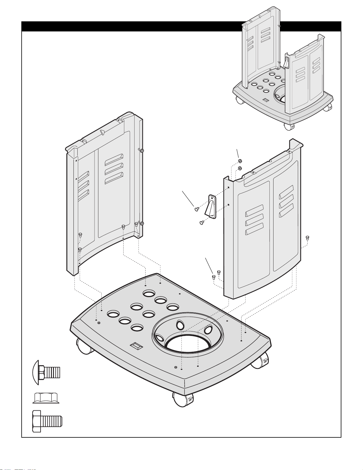
BASE CABINET ASSEMBLY
• Attach Cabinet side panels to base as shown.
NOTE: Right panel has two holes located on
the top right corner for bottle opener.
• Attach bottle opener to right panel as shown.
18
FIG.2
Right hand
Panel
Assembled
View
SP84-18 (8)
1/4-20 X .5 HEX HD BOLT
SP84-18 (8) 1/4-20 X .5 HEX
HD BOLT
SP53-16 (2) 1/4-20
NUT HEX HD FLANGED
SP53-16 (2) 1/4-20
NUT HEX HD FLANGED
SP83-18 (2) 1/4"-20X.50"
CARRIAGE BOLT
SP83-18 (2) 1/4"-20X.50"
CARRIAGE BOLT
Page 19
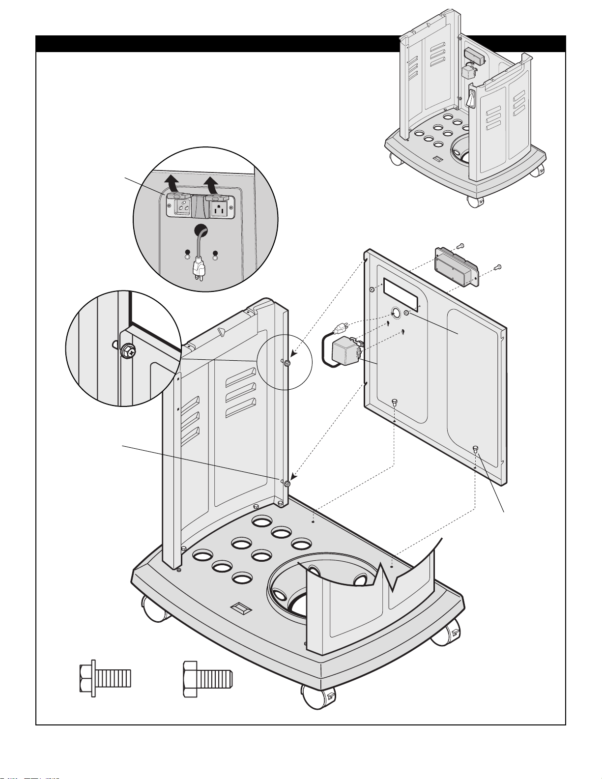
19
REAR PANEL ASSEMBLY
FIG.3
Assembled
View
SP46-21 (4) 1/4" X1/2"
SCREW HEX HD
SP46-21 (4) 1/4" X 1/2"
SCREW HEX HD
SP84-18 (2) 1/4-20 X .5
HEX HD BOLT
SP84-18 (2) 1/4-20 X .5
HEX HD BOLT
TRANSFORMER
BOX
SP54-21 (2) #10-24
SCREW
SP43-16 (2)
#10-24 NUT
• Attach rear panel by sliding notches over screws on side panels as
shown. Tighten screws.
• Install Electrical box with Screws and Nuts as shown. Ensure
Electrical box is installed so outlet covers open upwards.
• Install Transformer box into rear panel holes as shown.
INSTALL SO OUTLET
COVERS OPEN
UPWARDS
Page 20
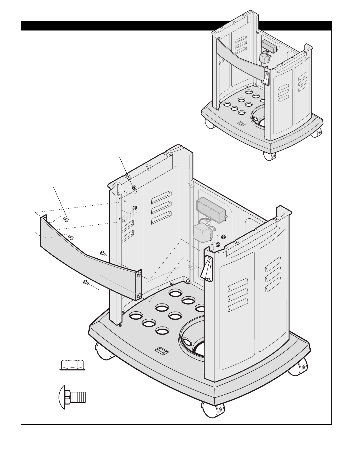
20
TRIM PANEL ASSEMBLY
• Attach top trim panel as shown.
Tighten screws.
FIG.4
Assembled
View
SP83-18 (4) 1/4"-20 X .50" CARRIAGE BOLT
SP83-18 (4) 1/4"-20X.50"
CARRIAGE BOLT
SP53-16 (4) 1/4-20
NUT HEX HD FLANGED
SP53-16 (4) 1/4-20 NUT HEX HD FLANGED
Page 21
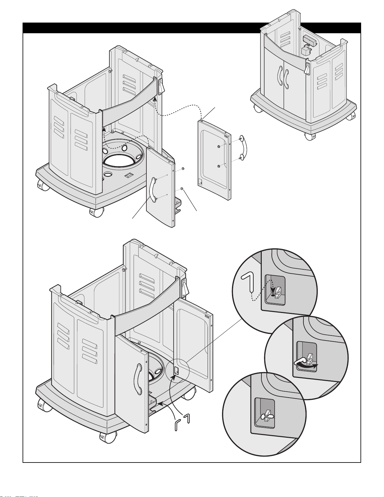
21
FRONT DOOR ASSEMBLY
• Install door handles as shown.
• Slide top pins on doors into
upper holes as shown.
• A) Drop locking pins through lower
holes in door into base assembly.
• B) Once in position rotate pins into
locked position as shown.
FIG.5
Assembled
View
A)
B)
Locked position
Pin
SP17-32 (2)
HINGE PIN LOWER
#10-24 NUT HEX HD
FLANGED
PIN
HANDLE
Page 22
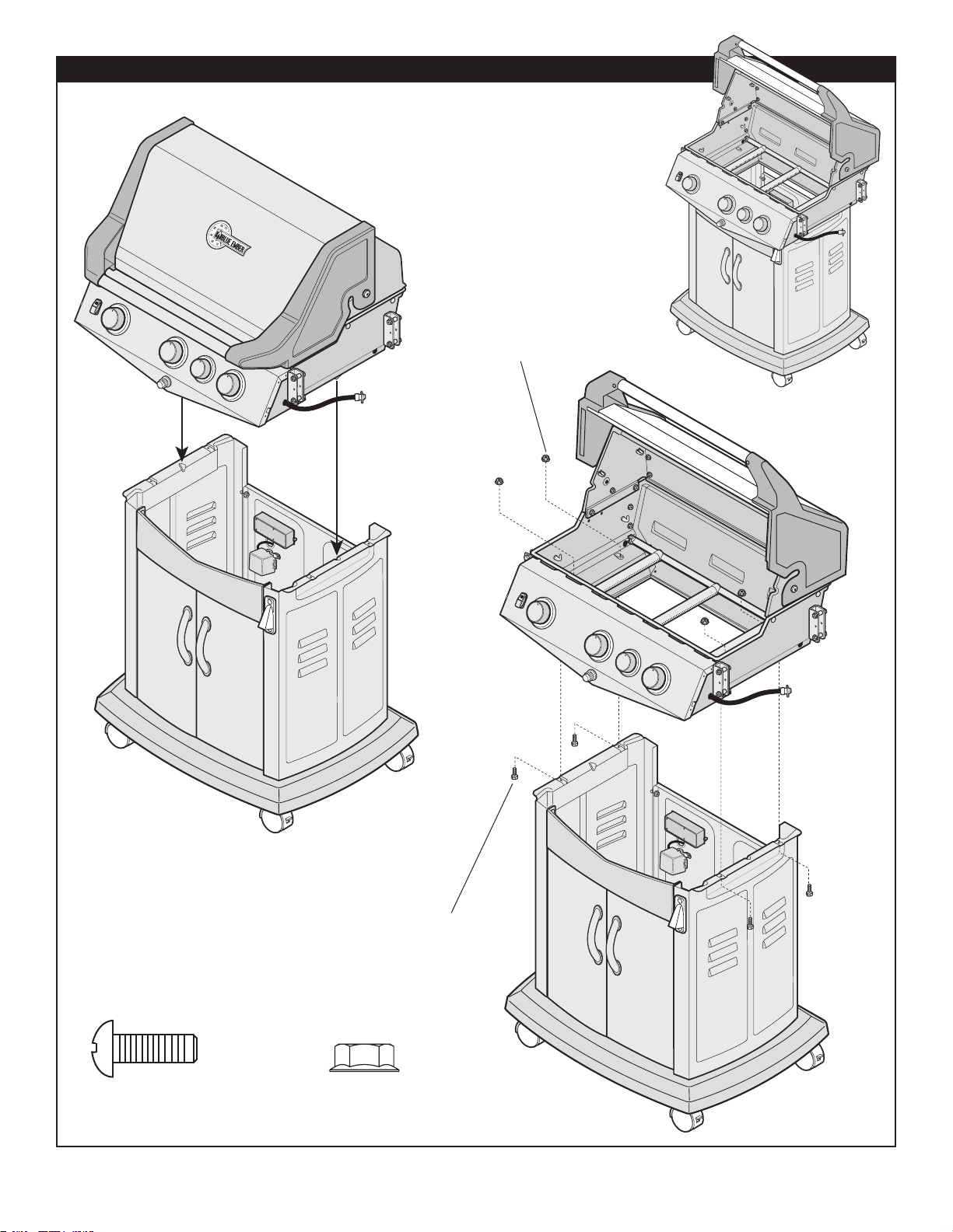
22
CASTING ASSEMBLY
• Using two people, lower the top cover
assembly carefully onto base and
attach as shown.
FIG.6
Assembled
View
Important
Center tabs
under cover
assembly
with notches
in cabinet.
SP86-18 (4) 1/4" -20 X .75"
MACHINE SCREW
SP86-18 (4)
1/4"
-20 X .75"
MACHINE SCREW
SP53-16 (4) 1/4-20
NUT
HEX HD FLANGED
SP53-16 (4) 1/4-20
NUT HEX HD FLANGED
Page 23
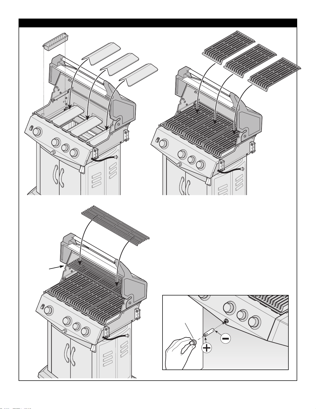
23
GRILL ASSEMBLY
Step 1
• Rest the ends of heat plates into notches inside
casting as shown.
Step 2
• Install Smoker on hooks inside cover assembly.
Step 3
• Install 3 grills as shown.
Step 4
• Install warming rack into supports as shown.
Step 5
• Install AA BATTERY into ignitor,
put - (negative) side of battery in first.
Step 4
Step 3
Step 1
Step 2
BATTERY
IGNITOR
CAP
Put - (negative) side of
battery in first
FIG.7
E
L
I
P
AA
•
Y
R
E
T
T
A
B
Page 24
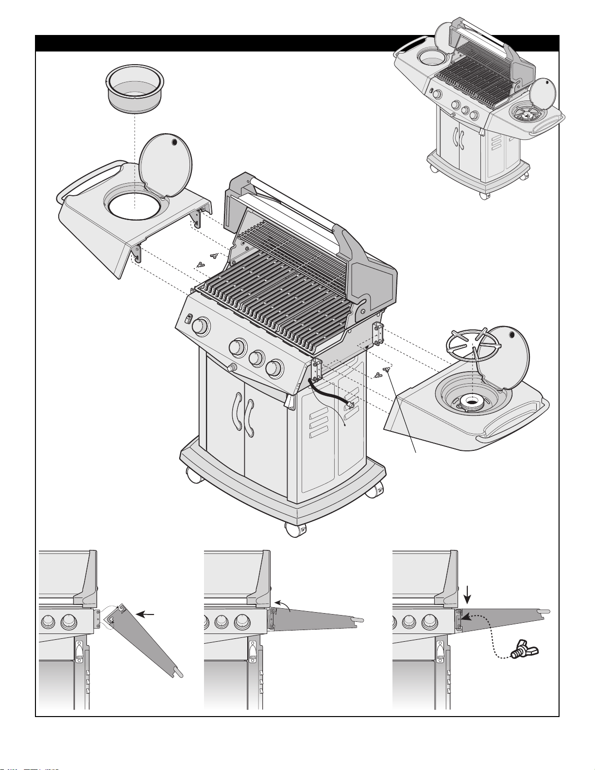
24
SIDE SHELF ASSEMBLY
• Position side shelves
onto shelf brackets as
shown (A). Lift shelf and
drop into locking position
(B). Insert wingbolt into
middle hole in bracket to
lock shelf in position (C).
• Position ice bucket
as shown.
• Insert side burner grill.
Assembled
View
FIG.8
(A)
(B)
(C)
SP87-18 1/4 20 X .5
(4) SHELF LOCK WING BOLT
SP87-18 1/4 20 X .5
(4) WING BOLT
Page 25
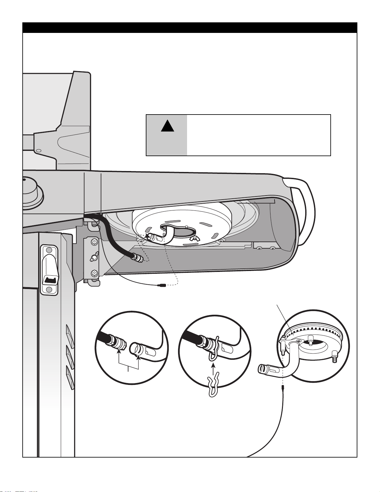
25
SIDE BURNER HOSE ASSEMBLY
• Position hose into end of side burner venturi tube until groves
line up (A). Snap clip into the groove on side burner tube to
secure parts (B).
• Check hose to ensure it is securely positioned in tube end.
• Attach side burner Ignitor wire to terminal on side burner bracket.
Ensure you read and understand warning below before proceeding.
FIG.9
(A)
(B)
Grooves
Ignitor Wire
Electrode
WARNING
!
CAUTION: NEVER LIGHT THE SIDE BURNER WHILE
THE SIDE BURNER LID IS DOWN. THE SIDE BURNER
LID SHOULD ALWAYS BE OPEN WHILE SIDE BURNER
IS LIT. FAILURE TO DO SO MAY CAUSE SERIOUS
BODILY INJURY AND/OR PROPERTY DAMAGE.
Page 26
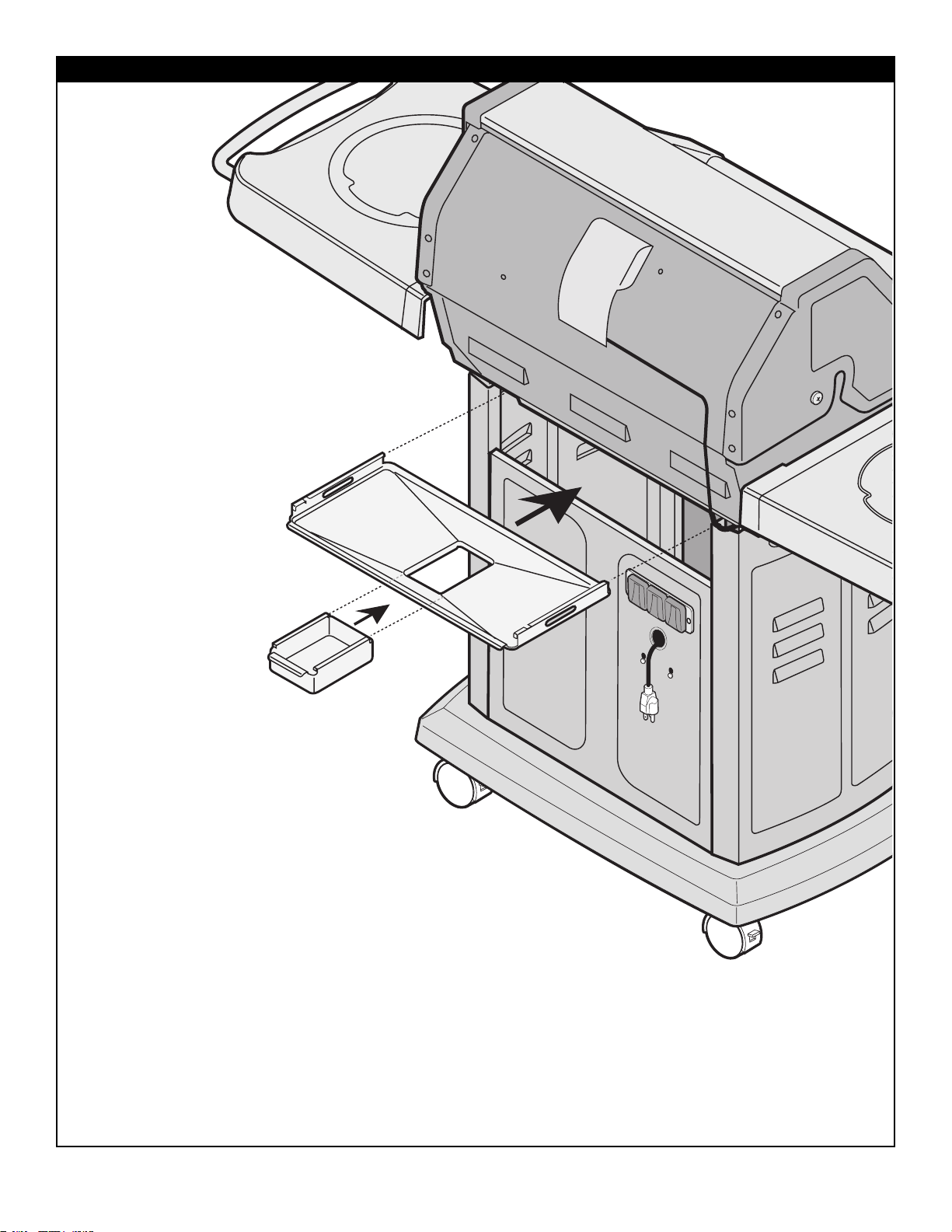
26
GREASE TRAP ASSEMBLY
FIG.10
• Slide in grease pan
and Grease cup as
shown.
• Ensure grease trap and
cup are in position before
using the BBQ.
Page 27
27
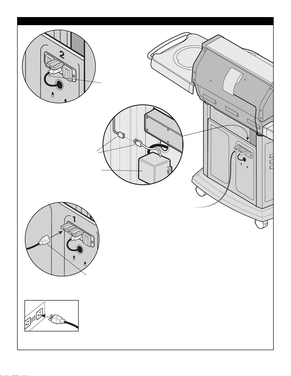
PROVIDING POWER TO YOUR BARBEQUE
IMPORTANT: To provide power to the barbecue,
plug a grounded electrical cord into rear receptacle box as shown.
Plug electrical cord into properly grounded GFI
(Ground Fault Interrupt) receptacle.
If use of an extension cord is required, be sure that it is a
minimum 16 AWG, 3 wire well insulated cord, marked for
OUTDOOR USE ONLY and properly grounded.
CAUTION: To ensure continued protection against risk of electric shock,
connect to properly earthed outlets only.
Transformer
Box
Step 2
IMPORTANT: Assemble light
switch wires to Internal Transformer
box as shown.
Light Switch
Wires
Grounded
Electrical Cord
Step 1
Step 3
Transformer
Cord
FIG.11
• Plug the factory
supplied, three
prong plug for the
transformer into the
receptacle box at the
back of the unit.
Page 28
28
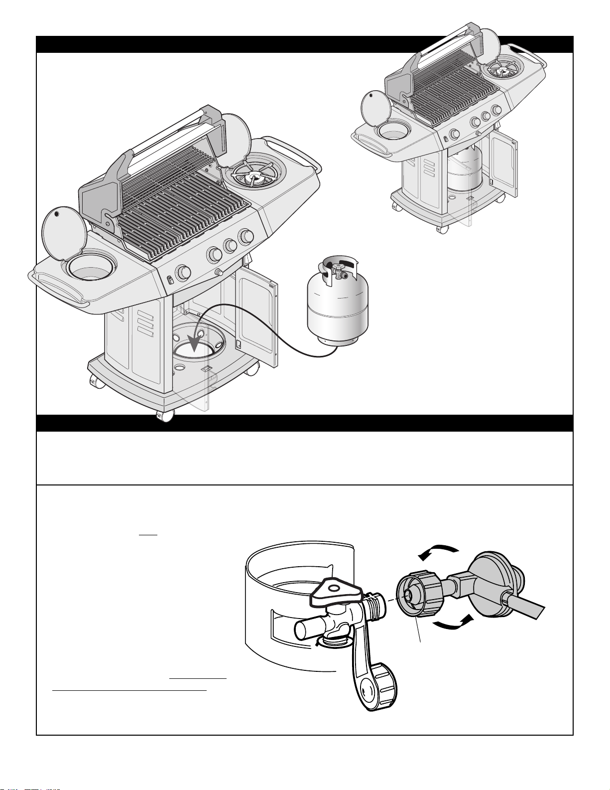
TANK ASSEMBLY
• Position tank into tank support as shown.
HOSE/REGULATOR
FIG.12
Before attaching hose/regulator to
tank, be sure cylinder valve and
appliance valves are OFF
.
The Q.C.C.1 cylinder valve has an internal
back check module which will not allow gas
to flow until a connection has been made.
The valve is turned off by rotating the
handwheel (Fig. 3, Use and Care)
Clockwise (left to right) until it stops. When
attaching regulator to tank, make sure that
the small probe (Fig. 13) in the nipple is
centered in the mating Q.C.C.1 cylinder
valve, turn the right hand threaded Q.C.C.1
nut onto the valve in a clockwise motion
until there is a positive stop. DO NOT USE
A WRENCH, HAND TIGHTEN ONLY.
IMPORTANT: Ensure hose assembly
does not contact the casting, or any other
parts which will get hot.
Q.C.C.I. NUT
TANK
HOSE/REGULATOR
WARNING: Before proceeding with the following steps, ensure you have read: • L.P. Gas Cylinder • Hose and Regulator
Sections of the USE AND CARE INSTRUCTIONS located at the front of this manual. The L.P. gas cylinder, if supplied with your grill, has been
shipped empty for safety reasons. The cylinder must be purged of air, and filled, prior to use. Follow all directions under "L.P. Gas Cylinder - Filling"
section of the Use and Care Instructions.
FIG.13
Assembled
View
Tank Not
Included
Page 29
29
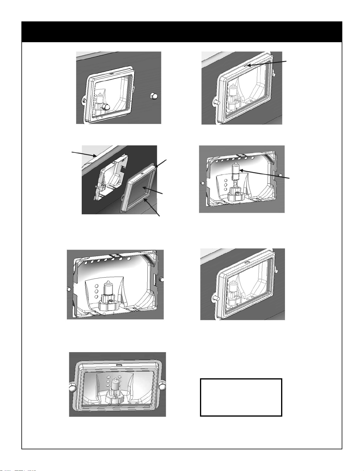
BULB REPLACEMENT INSTRUCTIONS
USE 20 WATTS OR SMALLER,
12 VOLT, TYPE JC BULB.
Bulb
1. Loosen two nuts. 2. Press tab on top of Glass Bezel.
3. Hold the Light Rain Guard, slowly
remove GLASS BEZEL, GLASS
GASKET, and GLASS.
Light
Rain
Guard
BULB
4. Hold the Light Rain Guard,
remove the light BULB.
5. Hold the Light Rain Guard,
replace the light BULB.
6. Hold the Light Rain Guard, place
GLASS GASKET, GLASS , and
GLASS BEZEL together into the
REFLECTOR.
7. Secure nuts.
Tab
Reflector
Glass
Gasket
NOTE: UNPLUG
ALL POWER TO
GRILL BEFORE
REPLACING
LIGHT.
Page 30
ITEM QTY. SP PART No. DESCRIPTION
1 1 SP155-42 COVER ASSY
1 SP37-33X COVER CAST END CAP LH
1 SP38-33X COVER CAST END CAP RH
1 SP87-9 COVER PANEL
1 SP88-9 COVER LINER
1 SP53-19 HANDLE
2 SP43-33 COVER PLUG
2 SP54-21 #10-24 X .5 RD HD SS PHILLIP
8 SP40-16 SELF-THREAD LOCKNUT 1/4"
2 SP8-25 POST STOP
1 SP45-30 LOGO GAGE ASSEMBLY
2 2 SP92-18 COVER HINGE SHOULDER BOLT
3 2 SP53-16 1/4-20 NUT HEX HD FLANGED
4 1 SP276-42 BASE BACK PANEL ASS’Y
1 SP39-33X CAST END CAP LH
1 SP40-33X CAST END CAP RH
5 1 SP174-9X 2007 PANEL BACK
1 SP20-38 2007 LIGHT ASS’Y
1 SP95-6X 2007 LIGHT RAIN GUARD
2 SP47-21 8-32X.375 SS PANHEAD CREW
6 SP82-18 #10-24 .43 CARRIAGE BOLT
6 SP41-16 #10-24 NUT HEX HD FLANGED
6 4 SP83-18 1/4"-20X.50" CARRIAGE BOLT
7 4 SP53-16 1/4-20 NUT HEX HD FLANGED
8 1 SP163-3 WARMING RACK PORC 200 SQ"
9 1 SP5335-42 500 GRILL 4-VALVE BASE ASS’Y
1 SP41A-33X BASE CAST END CAP LH
1 SP42A-33X BASE CAST END CAP RH
1 SP89-9X BASE BACK PANEL
1 SP90-9X BASE FRONT PANEL
12 SP82-18 #10-24 .43 CARRIAGE BOLT
12 SP41-16 #10-24 NUT HEX HD FLANGED
4 SP54-6X BASE SHELF BRACKETS @.275
8 SP83-18 1/4"-20X.50" CARRIAGE BOLT
8 SP53-16 1/4-20 NUT HEX HD FLANGED
8 SP85-18 3/8" SHOLDER BOLT 1/4-20
8 SP53-16 1/4-20 NUT HEX HD FLANGED
1 SP92-9 HEAT BAFFLE
1 SP5028-31 CONSOLE 4 VALVE
3 SP46A-6 BEZEL MAIN
1 SP47A-6 BEZEL SIDE/ROTIS
13 SP42-21 #8-32-.5/16" RD HD SCREW
1 SP232A-4 VHR 4-VALVE 57,000 BTU
3 SP15-7 KNOB MAIN
1 SP16-7 KNOB SIDE/ROTIS
1 SP15-38 TOGGLE SWITCH
1 SP37-20 IGNITOR ELECTRONIC 4-POLE
12 SP43-21 #10X3/8 SCREW SELF TAP B
1 SP93-9 CONSOLE BAFFLE
1 SP67A-12 BURNER ASS’Y
3 SP68A-12 BURNER C/W AIR SHUTTER
3 SP93-5 AIR SHUTTER
3 SP62-21 #8 B X 1/4" PAN HD SCREW
1 SP53A-20 BURNER CROSS IGNITOR MANUAL
3 SP44-21 #10-24 X.375" HEX HD FLANGED SCREW
3 SP54-20 IGNITOR MAIN BURNER
2 SP45-21 #10 X 1" HEX HD B SCREW
10 1 SP91-9 GREASE PAN
11 1 SP103-9 GREASE CUP
12 3 SP94A-9 SMART BAR
13 3 SP164A-3 CAST IRON COOK GRATE
14 1 SP95-9X CAB BACK PANEL
15 1 SP107-9X CAB PANEL FRONT
16 1 SP165-42 PANEL RH ASS’Y
1 SP105-9X PANEL SIDE RH
1 SP57-6X CART BRACKET RH
2 SP46-21 1/4" X1/2" SCREW HEX HD SELF TAP B
17 1 SP166-42 PANEL LH ASS’Y
1 SP106-9X PANEL SIDE LH
1 SP56-6X CART BRACKET LH
2 SP46-21 1/4" X1/2" SCREW HEX HD SELF TAP B
18 1 SP104A-9X BOTTOM PAN RESIN
10 SP46-16 1/4-20 INSERT NUT
19 10 SP53-16 1/4-20 NUT HEX HD FLANGED
20 6 SP83-18 1/4"-20X.50" CARRIAGE BOLT
21 10 SP84-18 1/4-20 X .5 HEX HD BOLT
22 4 SP86-18 1/4"-20 X .75" MACHINE SCREW
30
4 SP59-16 3/8-16 INSERT NUT
X
X
X
(X DESIGNATES COLOR BL=BLUE, B=BLACK, C=CHARCOAL)
Page 31
ITEM QTY. SP PART No. DESCRIPTION
23 SP163-42 DOOR LH ASSY
1 SP108-9 DOOR LH PANEL
1 SP58-6 DOOR INSIDE LH
1 SP41-15 MAGNET
8 SP47-21 #8-32 X 3/8" PAN HD PHILIP
1 SP17-32 HINGE PIN LOWER
1 SP20-32 HINGE PIN TOP
1 SP54A-19 HANDLE CHROME PLATE
2 SP41-16 #10-24 HEX NUT
24 SP164-42 DOOR RH ASSY
1 SP109-9 DOOR RH PANEL
1 SP59-6 DOOR INSIDE RH
1 SP41-15 MAGNET
8 SP47-21 #8-32 X 3/8" PAN HD PHILIP
1 SP17-32 HINGE PIN LOWER
1 SP20-32 HINGE PIN TOP
1 SP54A-19 HANDLE CHROME PLATE
2 SP41-16 #10-24 HEX NUT
25 4 SP24A-22 CASTERS 3"
26 SP260-42 RESIN SIDE SHELF ASS’Y
1 SP166-9X RESIN SIDE SHELF LH
1 SP48-6X SHELF BRACKET LH
1 SP49-6X SHELF BRACKET RH
2 SP45-16 1/4-20 HEX HEAD WELD NUT
8 SP49-21 #10" X.75" HEX FLANGE HD SELF TAP AB
1 SP53-6 SHELF TRIM LH
2 SP43-21 #10X3/8 SCREW SELF TAP AB
1 SP12-1 SHELF COVER
1 SP176A-3 HINGE WIRE
1 SP55-19 TOWEL BAR
1 SP83-6 TOOL HOOK LH
2 SP57-21 #10 X .5” RD HD SCREW AB
1 SP97-9 ICE BUCKET
27 2 SP87-18 1/4 20X.5 WING BOLT
28 SP5336-42 RESIN SIDE BURNER ASS’Y
1 SP12-2X SIDE BURNER RESIN BASE
1 SP55-6 SHELF TRIM RH
6 SP43-21 #10X3/8 SCREW SELF TAP AB
1 SP167-9 SIDE BURNER PAN
1 SP5009-1 SIDE BURNER COVER
1 SP176A-3 HINGE WIRE
1 SP60-16 SPEED NUT PUSH ON
1 SP262-42 RESIN SIDE BURNER BACK BKT ASS’Y
1 SP48-6 SHELF BRACKET LH
1 SP97-6 SBURNER BACK BKT
1 SP45-16 1/4-20 HEX HEAD WELD NUT
1 SP263-42 RESIN SIDE BURNER FRONT BKT ASS’Y
1 SP49-6 SHELF BRACKET RH
1 SP98-6 SBURNER FRONT BKT
1 SP45-16 1/4-20 HEX HEAD WELD NUT
1 SP55-19 TOWEL BAR
8 SP49-21 #10"X.75" HEX FLANGE HD SELF TAP AB
29 1 SP70A-12 SIDE BURNER ASS’Y
1 SP71-12 BRASS COVER
1 SP72A-12 BASE
1 SP41-13 VENTURI
1 SP56-20 IGNITOR
3 SP64-21 #8-32-.5/16" RD HD SCREW
1 SP165-3 CAST IRON GRATE
2 SP87-18 1/4 20X.5 WING BOLT
30 1 SP50-6 BOTTLE OPENER
31 1 SP7-1 SMOKER COVER
32 1 SP5-2 SMOKER BASE
33 2 SP48-21 #12 X.500 L-SCREW @.014
2 SP43-16 #10-24 HEX NUT
35 1 SP19-38 TRANSFORMER
36 1 SP110-9 WINE BUCKET CONDIMENT
37 1 SP111-9 CONDIMENT TRAY
38 1 SP56-45 BATTERY AA
31
34 1 SP17-38 RESIN 2-OUTLET / 1INLET BOX
X
X
2 SP54-21 #10-24 x .5 RD HD SS PHILLIPS
(X DESIGNATES COLOR BL=BLUE, B=BLACK, C=CHARCOAL
Page 32
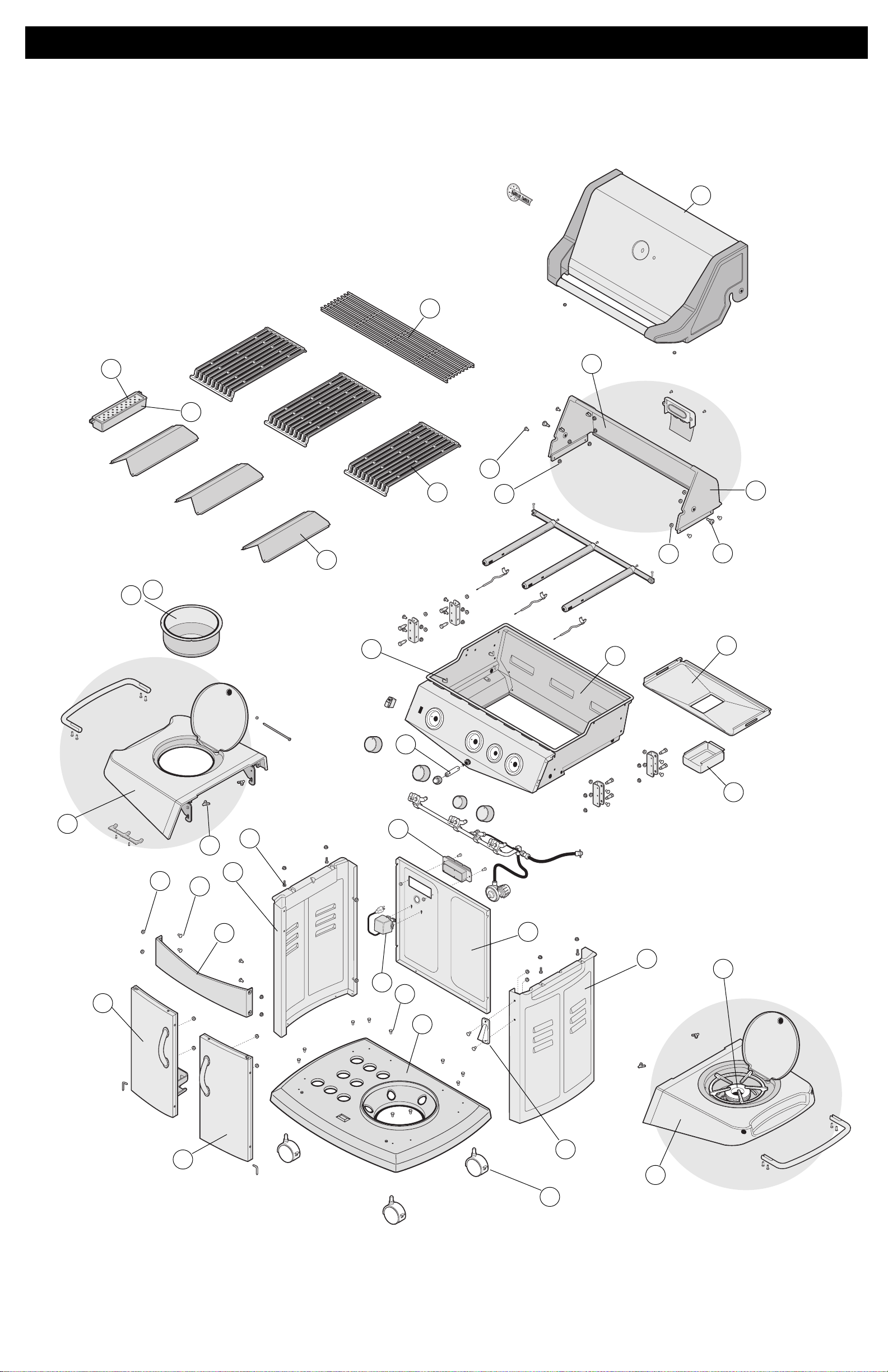
1
EXPLODED ASSEMBLY
2
4
5
9
8
7
6
3
10
11
12
13
14
15
16
17
18
21
20
19
22
23
24
25
26
27
28
29
30
31
32
33
34
35
38
36
37
FG50057
LE
I
A
A
P
•
Y
TER
AT
B
 Loading...