

Page 1

Hazardous Fire or Explosion may result if
these instructions are ignored.
It is your responsibility to see that your new barbeque is
assembled, installed, maintained and cared for properly.
Failing to carefully follow the instructions in this manual
could result in serious bodily injury and/or property damage.
WARNING!
FOR YOUR SAFETY
FOR YOUR SAFETY
THIS APPLIANCE IS FOR OUTDOOR USE ONLY
!
• Do not store or use gasoline or other flammable vapours
and liquids in the vicinity of this or any other appliance.
• An LP cylinder not connected for use shall not be stored
in the vicinity of this or any other appliance.
SP908-37
Full Model # (from outer carton):
Date Purchased:
Serial Number
(from rating plate):
SAVE THIS MANUAL FOR YOUR FUTURE REFERENCE
Installer must leave these instructions
with the consumer for future reference.
TEL.
1-800-387-8643
FAX
1-888-801-7772
www.fiestabbq.com
FIESTA BARBEQUES™ LIMITED
2 Walker Drive, Brampton, Ontario L6T 5E1
info
KEEP YOUR RECEIPT AS PROOF OF
PURCHASE TO VALIDATE THE
WARRANTY. ATTACH YOUR RECEIPT
TO THE INSIDE COVER OF THIS
MANUAL FOR EASY REFERENCE.
Manual For The Use & Care of Your
OUTDOOR GAS BARBEQUE / GRILL
TM
WARRANTY INFORMATION
IF YOU SMELL GAS:
1. Shut off gas supply to the appliance.
2. Extinguish any open flame.
3. Open lid.
4. If odour continues, immediately call your gas supplier
or your fire department.
MODELS A24027
The Model Shown Has Options.
Model Purchased May Not Be As Shown
SP908-37 A24027-150.qxd 03/10/2003 4:45 PM Page 1
Page 2

12
FIG. 1
A
BACK
SUPPORT
CASTING
SUPPORT
LEG
CAP
LEFT LEG
RIGHT LEG
(BAG PACK SP137-24)
1/4" NUT
BOTTOM PAN
FIGURE 1.
1. Take leg (rear left), insert leg
extension plug and attach
using 1 1/2" bolt, washer
and nut. (Fig. A)
2. Attach wheels and right legs
as shown using (2) Wheel
bolts, washers and nuts. (B)
3. Attach back support as
shown using 1 1/2" bolts and
nuts.
4. Attach (2) casting supports to
rear legs ONLY using (2)
1 1/2" bolts and nuts.
Tighten all connections and
insert (3) leg caps.
ASSEMBLY INSTRUCTIONS:
STEP 1
STEP 3
STEP 4
STEP 2
TOOLS REQUIRED:
11 and 13mm spanner, small adjustable spanner,
crosshead & slothead screwdrivers.
• Extra Common Nuts & Bolts are supplied.
• Refer to diagrams to assemble your grill.
LEG
EXTENSION
PLUG
1-1/2" BOLT
WASHER
NUT
LEG EXTENSION
PLUG
LEG
CAP
WASHER
1-1/2" BOLT
WASHER
NOTE:ENSURE TANK
LOCATORS
ARE AT RIGHT END
WHEELWHEEL BOLT
B
WASHER
NUT
LEG
WHEEL BOLT
WHEEL
1/4"-20 X 1 1/2" BOLT (X5)
1/4"-20 NUT (X7)
WASHER (3)
WHEEL BOLT (X2)
SP908-37 A24027-150.qxd 03/10/2003 4:45 PM Page 12
Page 3
13
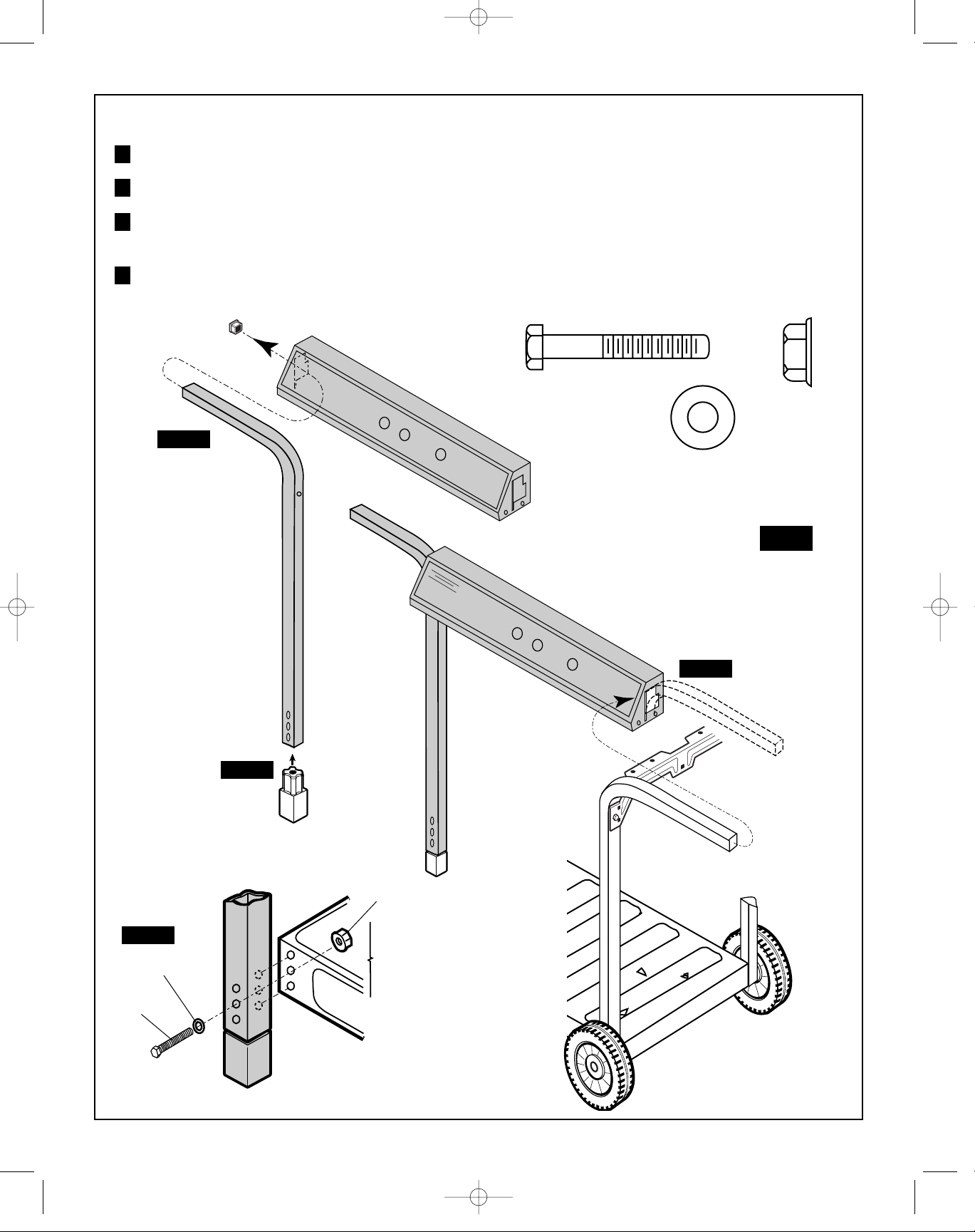
FIGURE 2.
Insert leg plug in front left leg.
Position remaining left front leg through console slot and insert leg cap.
Position console over right front leg through console slot. Casting support must locate BETWEEN
leg and console.
Position left leg on bottom pan and loosely assemble with 1 1/2" bolt, washer and nut.
1
2
3
FIG. 2
1 1/2" BOLT
1/4" NUT
1 1/2"
BOLT
WASHER
1/4" WASHER
STEP 2
STEP 3
CONSOLE
CASTING
SUPPORT
NUT
LEG
EXTENSION
PLUG
4
STEP 4
STEP 1
LEG
PLUG
(BAG PACK SP137-24)
LEG
CAP
SP908-37 A24027-150.qxd 03/10/2003 4:45 PM Page 13
Page 4

14
FIGURE 3.
Loosely assemble left leg to console with casting
bracket BETWEEN as shown with 1 1/2" bolt
and nut.
Assemble right leg to console same as Step 5.
Align and square console and tighten all
connections, Steps 4, 5, 6.
5
6
STEP 6
NOTE:
FIG. 3
LEFT
FRONT
VIEW
STEP 5
1 1/2" BOLT
NUT
STEP 6
STEP 5
1 1/2" BOLT
NUT
SP908-37 A24027-150.qxd 03/10/2003 4:45 PM Page 14
Page 5
15
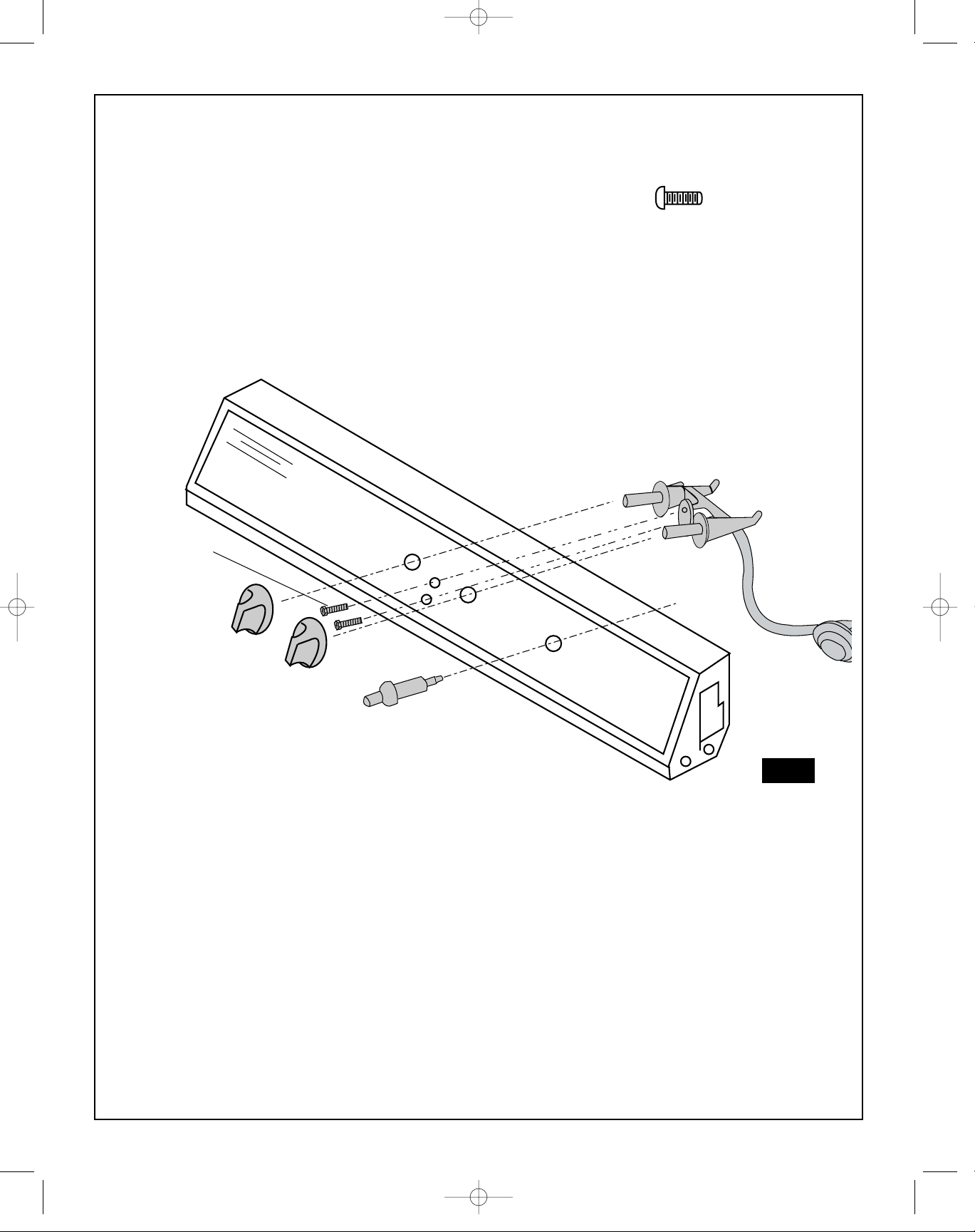
FIGURE 4.
Attach valve assembly to console as
shown using 3/8" screws. Insert push
button ignitor and snap into place.
Push on valve knobs.
SCREW (X2)
#6-32 X 3/8"
VALVE
ASSEMBLY
CONSOLE
KNOB
IGNITOR
FIG. 4
SCREW
SP908-37 A24027-150.qxd 03/10/2003 4:45 PM Page 15
Page 6
16
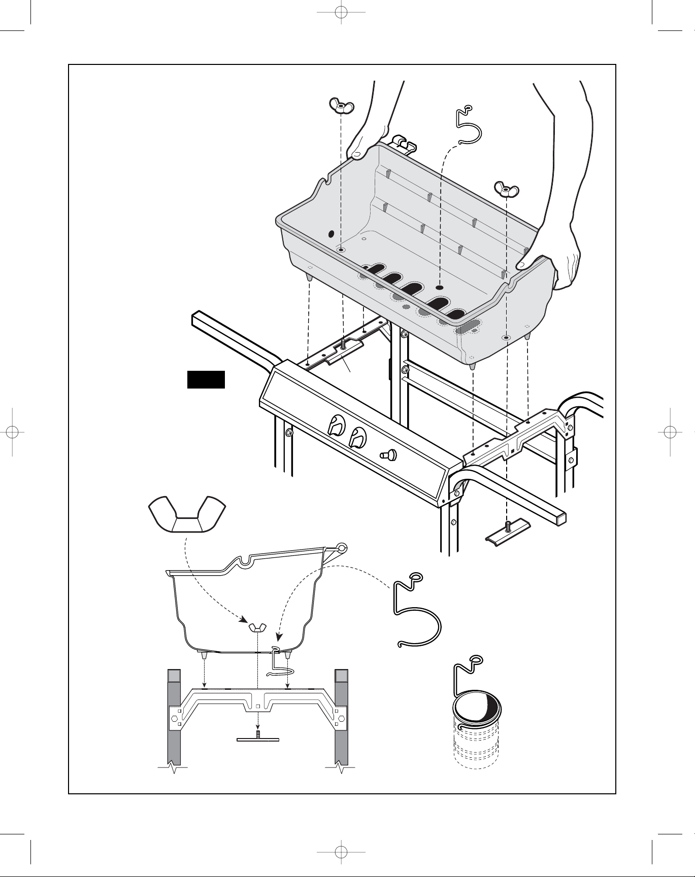
FIGURE 5.
• Position base on brackets
as shown.
• Position wing brackets as
shown and secure with wing
nuts.
• Insert grease clip through
hole as shown.
FIG. 5
(BAG SP137-24)
1/4"-20 WING NUT (X2)
GREASE CLIP
BASE
WING NUT
WING NUT
WING BRACKET
WING BRACKET
GREASE CLIP
WING
BRACKET
Grease cup not
supplied.
Any metal tin
(i.e. vegetable tin)
will work.
SP908-37 A24027-150.qxd 03/10/2003 4:45 PM Page 16
Page 7
17
BURNER
BOTTOM
VIEW
FIG. 6
IGNITOR
CLIP
END VIEW
IGNITOR CLIP
BURNER
BURNER
ELECTRODE
ELECTRODE
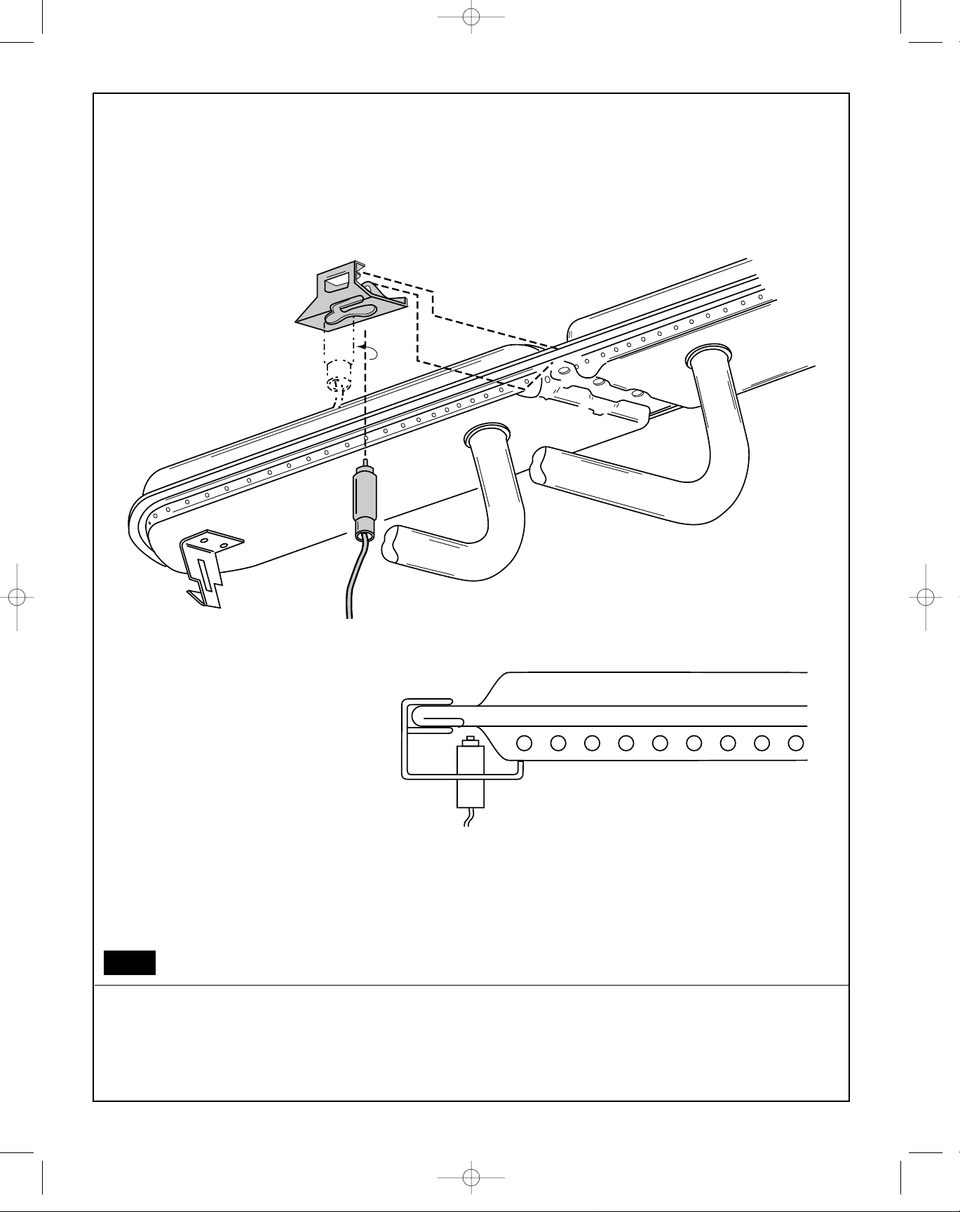
FIGURE 6.
Carefully insert and snap ignitor electrode into ignitor clip as shown. Push into left hole with a twisting motion.
Push clip assembly into lower centre groove of burner as shown. Ensure clip is firmly in place by pushing the
bottom lip over the 2 bumps on the burner underside.
SP908-37 A24027-150.qxd 03/10/2003 4:45 PM Page 17
Page 8
18
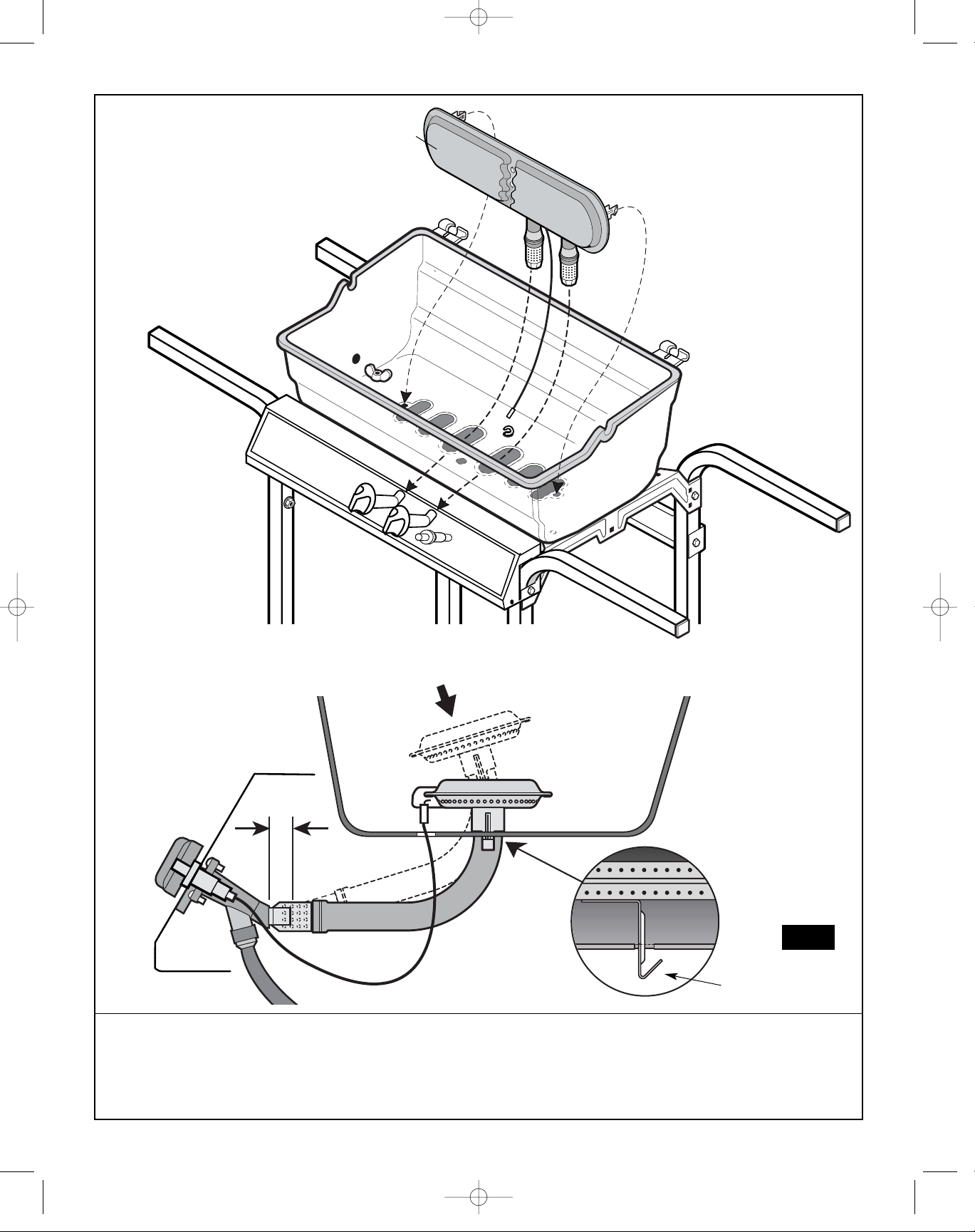
FIGURE 7.
Carefully install burner through holes in bottom of casting. Ensure end of ignitor electrode and wire fit down
through hole in casting, and electrode does not get damaged. Also ensure burner legs fit into casting slots and
that venturi tube is centered over valve orifice by 10mm. Attach wire to ignitor end terminal.
BASE
CASTING
VENTURI
BURNER
BURNER
IGNITOR
WIRE
FIG. 7
BURNER FEET
3/8"
BASE
CASTING
SP908-37 A24027-150.qxd 03/10/2003 4:45 PM Page 18
Page 9
19
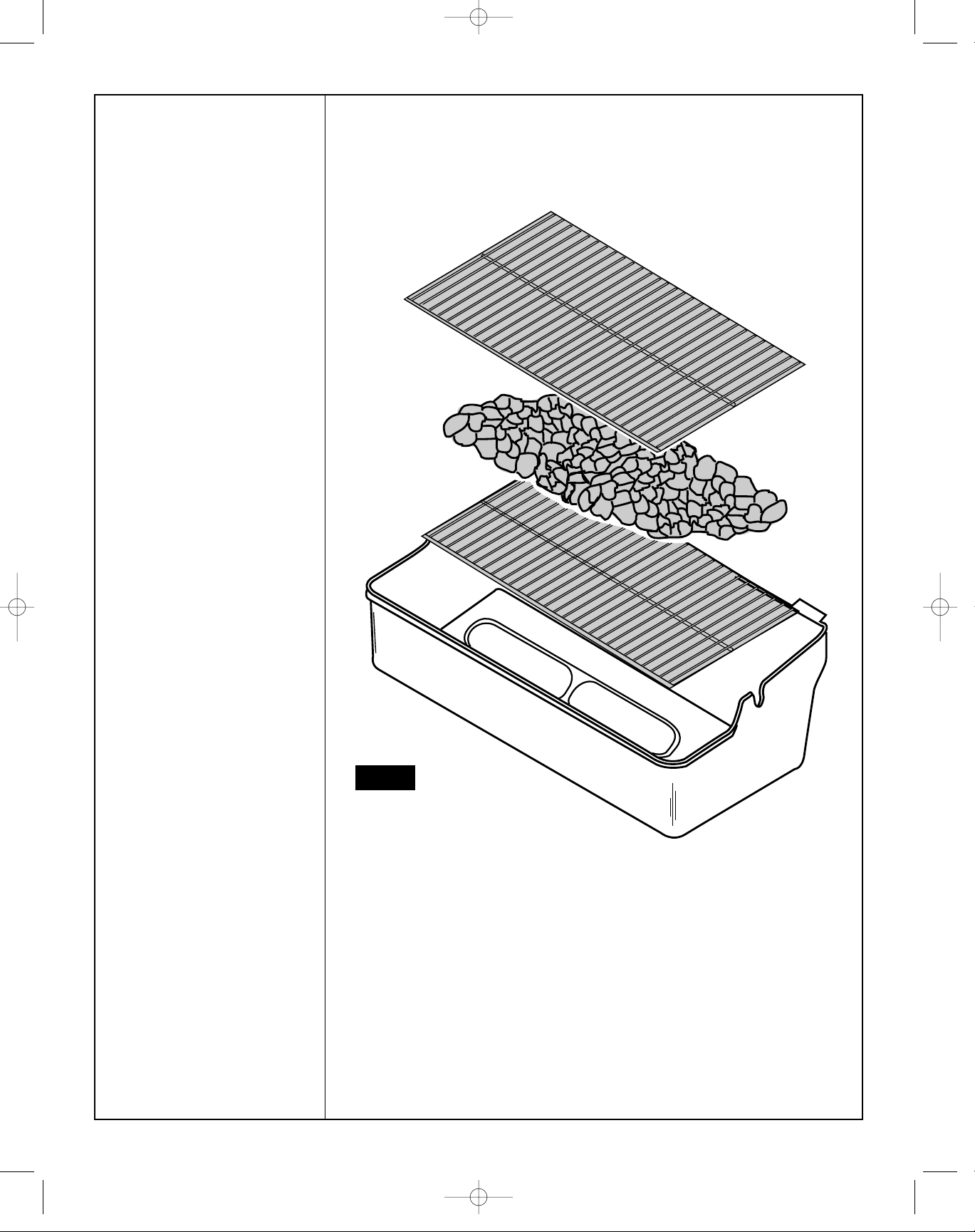
FIGURE 8.
Install lava grill, lava rock,
and cooking grill.
FIG. 8
LAVA GRILL
COOKING GRILL
LAVA ROCK
SP908-37 A24027-150.qxd 03/10/2003 4:45 PM Page 19
Page 10
20
CLIP
WING NUT
BOLT
HANDLE
COVER
GASKET
SPACER
FIG. 9
(BAG SP137-24)
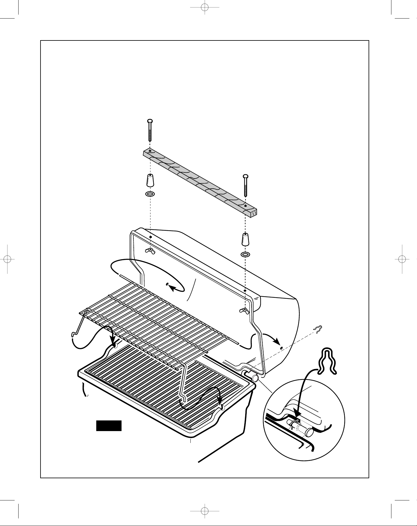
FIGURE 9.
• Position cover and secure from rear with spring clip in groove on right hinge pin.
• Install front handle as shown using #10 x 3" bolts, plastic spacer, heat gasket and
wing nuts. (BAG SP11A-24)
• Install warming rack.
WARMING RACK
SP908-37 A24027-150.qxd 03/10/2003 4:45 PM Page 20
Page 11
21
1" CROSSHEAD SCREWS
1" CROSSHEAD SCREWS (X8)
(BAG SP137-24)
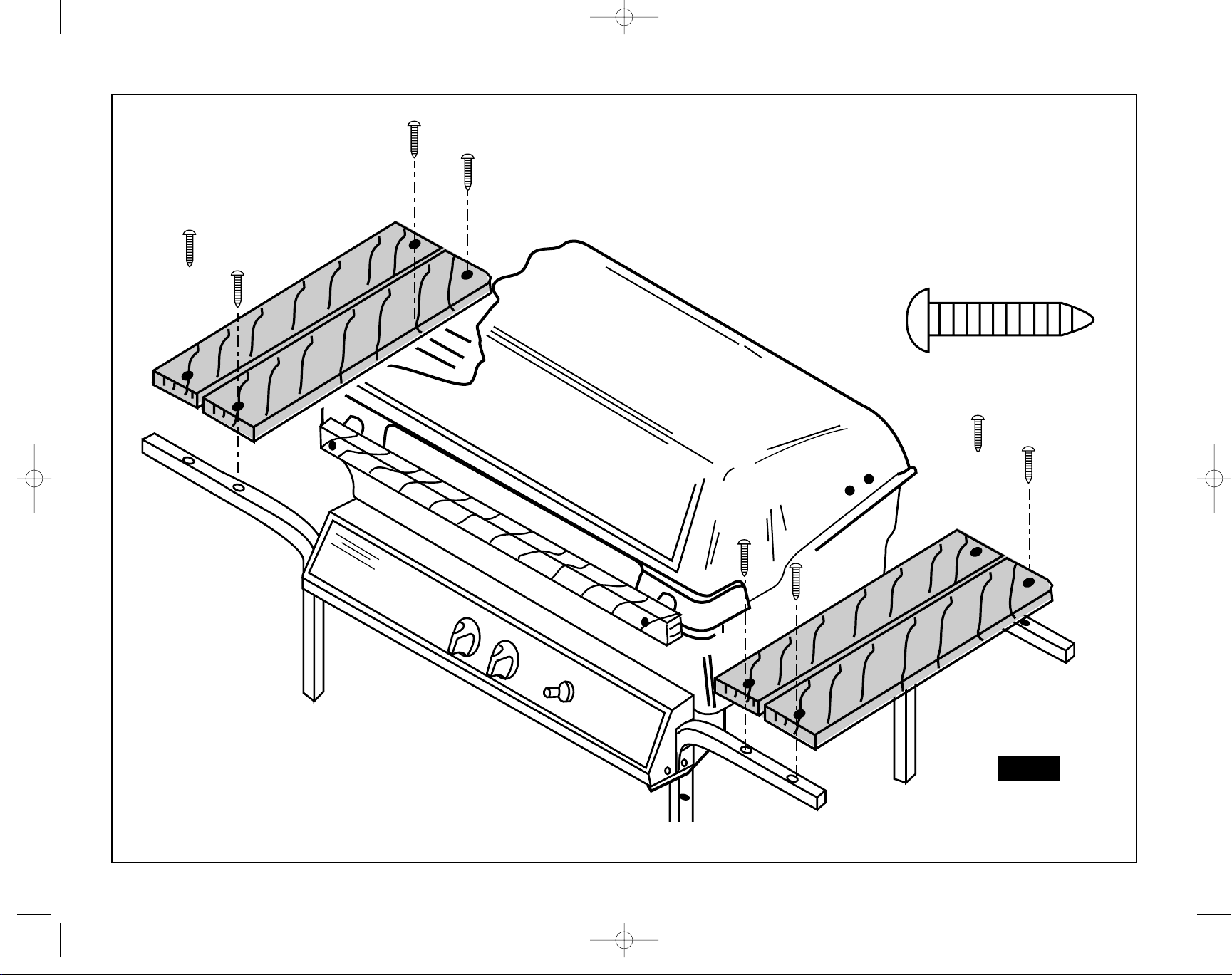
FIGURE 10.
Attach shelf wood as shown using 1" Crosshead Screws.
Long overhang goes toward front.
FIG. 10
SHELF WOOD
SP908-37 A24027-150.qxd 03/10/2003 4:45 PM Page 21
Page 12
22
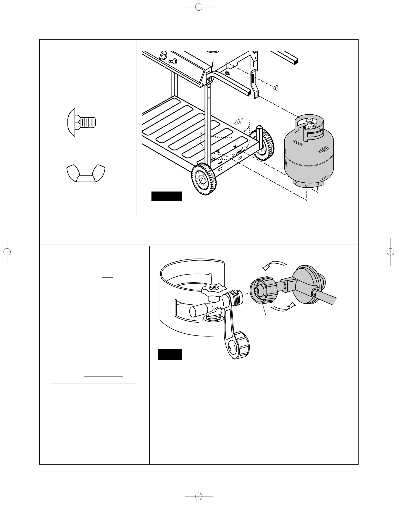
FIGURE 11.
Loosely attach tank bracket
using carriage bolt and wing
nut. Position tank on pan
tank locator. Raise tank
bracket and position over
tank ring, tighten wing nut.
CARRIAGE
BOLT
WING
NUT
TANK
Fig. 11
1/4" X 1/2" CARRIAGE BOLT
1/4"-20 WING NUT
FIGURE 12.
Before attaching hose/regulator to
tank, be sure cylinder valve and
appliance valves are OFF. The
Q.C.C.1 cylinder valve has an internal
back check module which will not
allow gas to flow until a connection
has been made. The valve is turned
off by rotating the handwheel
(Fig. 2B, Use and Care) Clockwise (left
to right) until it stops. When attaching
regulator to tank, make sure that the
small probe (Fig. 12) in the nipple is
centered in the mating Q.C.C.1
cylinder valve, turn the right hand
threaded Q.C.C.1 nut onto the valve in
a clockwise motion until there is a
positive stop. DO NOT USE A
WRENCH, HAND TIGHTEN ONLY.
Fig. 12
IMPORTANT: Ensure hose assembly
does not contact the casting, or any other
parts which will get hot.
Q.C.C.I. NUT
TANK
WARNING:
Before proceeding with the following steps, ensure you have read: • L.P. Gas Cylinder • Hose and Regulator
Sections of the USE AND CARE INSTRUCTIONS located at the front of this manual. The L.P. gas cylinder, if supplied with your grill, has been
shipped empty for safety reasons. The cylinder must be purged of air, and filled, prior to use. Follow all directions under "L.P. Gas Cylinder - Filling"
section of the Use and Care Instructions.
HOSE/REGULATOR
TANK NOT
INCLUDED
(BAG SP137-24)
SP908-37 A24027-150.qxd 03/10/2003 4:45 PM Page 22
Page 13
23
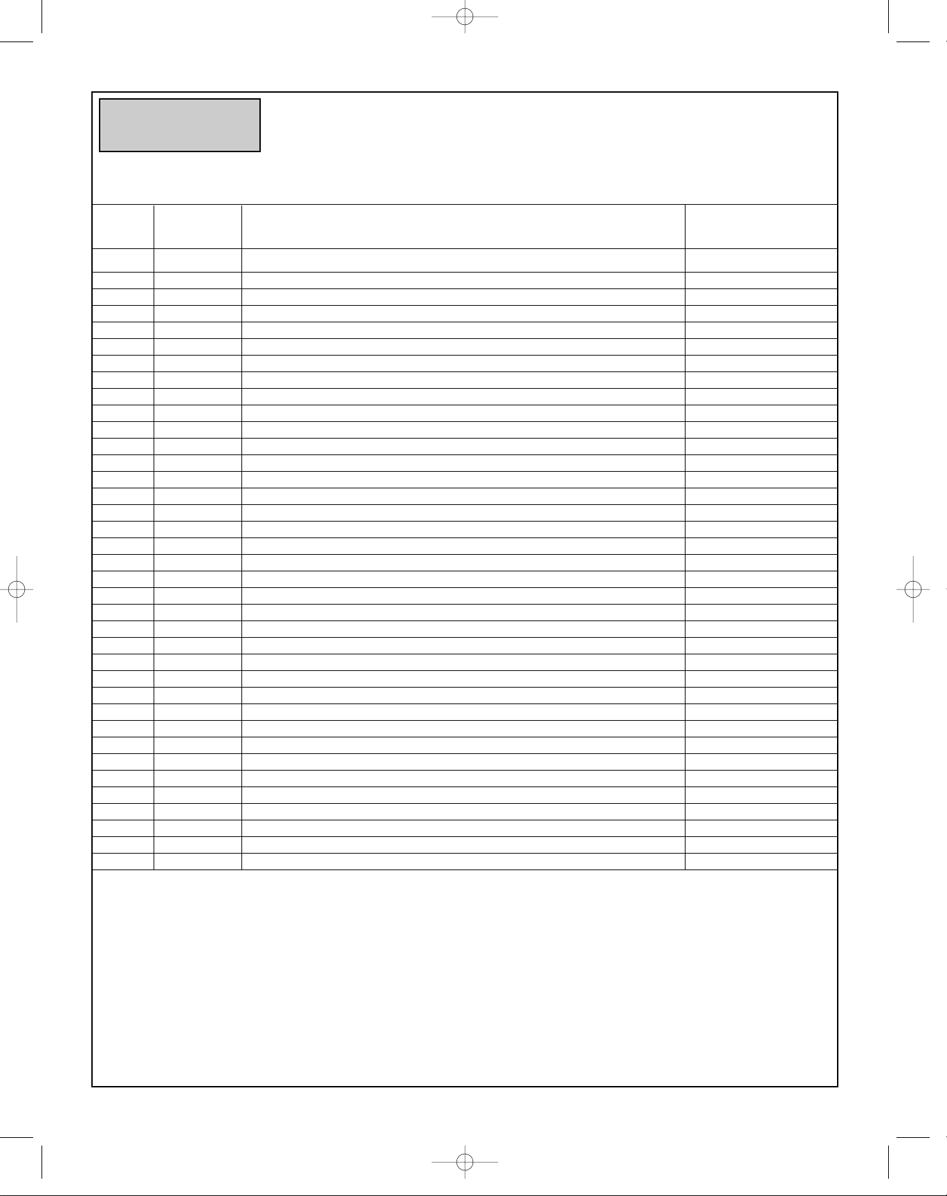
1 SM7-1B COVER CASTING 1
2 SP11A-24 COVER HANDLE BAG PACK (SPACER, BOLT, NUT) 1
3 SP8-19 COVER HANDLE WOOD 1
4 SP4-15 COVER SPRING CLIP 1
5 SP130A-3 WARMING RACK 1
6 SP19-3 COOKING GRILL 1
7 SP3-28 LAVA ROCK 1
8 SP17-3 LAVA GRILL 1
9 SM45A-12 BURNER ALUMINIZED 1
10 IGNITOR ELECTRODE AND WIRE 1
11 SM30-2B BASE CASTING 1
12 SP25-16 WING NUT 1/4-20 (BAG PACK SP137-24) 2
13 SP59-18 WING BRACKET (BAG PACK SP137-24) 2
14 SP6-15 GREASE CUP CLIP 1
15 SM146-4 VALVE ASSEMBLY (VHR) 1
16 SM14-31B CONSOLE 1
17 CONSOLE LABEL 1
18 SP4-7 CONSOLE KNOB 2
19 SP11-20 PUSH BUTTON IGNITOR KIT 1
20 SP14-21 #6-32 X 3/8" SCREW 2
21 SM82-6B CASTING BRACKET 2
22 SM35-8B LEG 4
23 SM17A-9B BOTTOM PAN 1
24 RATING PLATE/SERIAL # 1
25 SP78-23ND SHELF WOOD PACK OF 4 1
26 SP16-21 1” CROSSHEAD SCREW (BAG PACK SP137-24) 8
27 SP7-33B LEG EXTENSION PLUG 2
28 SP7-22 WHEEL 2
29 SP17-18 WHEEL BOLT 2
30 SP2-17 WASHER (BAG PACK SP137-24) 4
31 SP11-16 1/4" NUT (BAG PACK SP137-24) 11
32 SP1-33 LEG CAP (BAG PACK SP137-24) 4
33 SP7-18 1/4-20 X 1 1/2" BOLT HEX HD. (BAG PACK SP137-24) 9
34 SM35-6B BACK SUPPORT 1
35 SP36-6B TANK SUPPORT BRACKET 1
36 SP2-18 1/4-20 X 1/2" CARRIAGE BOLT (BAG PACK SP137-24) 1
37 SP2-16 1/4-20 WING NUT (BAG PACK SP137-24) 1
ITEM NO. PART NO. DESCRIPTION QTY.
A24027
Refer to the checklist in the “Prior To Use” section of the USE AND CARE
INSTRUCTIONS for the Leak Check and other safety checks which MUST BE
PERFORMED before lighting your grill.
Failure to follow those instructions may result in a hazardous fire or explosion causing
serious bodily injury and/or property damage.
WARNING
Fiesta Gas Barbeque Grill: Model A24027
How to Order Spare Parts: When ordering, always give the
following information:
1. The Part Number 2. The Model Description
3. The Part Colour 4. The Part Description
5. The Serial Number 6. Wood identify R-Redwood G-Grey N-Natural
NOTE: THE USE OF NON-FIESTA REPLACEMENT PARTS
AUTOMATICALLY VOIDS THE FIESTA BARBEQUE WARRANTY.
SP908-37 A24027-150.qxd 03/10/2003 4:45 PM Page 23
 Loading...