

Page 1
4025-7797-02
Printer Management Utility
Scanner Mode
for Fiery X3e 31C-M
Page 2

Foreword
Welcome
This manual describes the application and the operations of Printer
Management Utility, which is built into the Fiery X3e 31C-M (printer
controller), and the scanner mode.
Trademark Acknowledgements
Apple and Macintosh are registered trademarks of Apple Computer, Inc.
Ethernet is a registered trademark of Xerox Corporation.
Microsoft, Windows, and Windows NT are either registered trademarks or
trademarks of Microsoft Corporation in the United States and/or other
countries.
Netscape Communications, Netscape Communications’ logo, Netscape
Navigator, Netscape Communicator, and the Netscape are trademarks of
Netscape Communications Corporation in the U.S. and other countries.
PCL is a registered trademark of Hewlett-Packard Company Limited.
PostScript is a registered trademark of Adobe Systems, Inc.
EFI, Fiery and the Fiery logo are registered trademarks of Electronics For
Imaging, Inc. in the U.S. Patent and Trademark Office and/or certain other
foreign jurisdict io ns .
The Electronics For Imaging logo, Fiery Scan, Fiery WebScan and Fiery
WebTools are trademarks of Electronics For Imaging, Inc.
All other product names are trademarks or registered trademarks of their
respective holders.
The contents of this manual are subject to change without prior notice
as a result of improvements to the product.
i
Page 3

Contents
CONTENTS
Chapter 1 Using Printer Management Utility
1.1 System Requirements ................................. 1-2
1.2 Access .......................................................... 1-3
1.2.1 Operation ............................... ........................... 1-3
1.3 Screen Configuration .................................. 1-4
1.3.1 Logging in Using the Administrator Mode.....1-6
1.4 User Mode .................................................... 1-7
1.4.1 System Tab .......................................................1-7
1.4.2 File Tab............................................................1-16
1.4.3 Print Tab ..........................................................1-18
1.4.4 Scan Tab..........................................................1-27
1.5 Administration Mode ................................. 1-32
1.5.1 System Tab .....................................................1-32
1.5.2 File Tab............................................................1-38
1.5.3 Print Tab ..........................................................1-41
1.5.4 Scan Tab..........................................................1-42
1.5.5 Network Tab ....................................................1-44
Chapter 2 Using the Scanner Mode
2.1 Overview ...................................................... 2-2
2.1.1 Scan to E-mail...................................................2-3
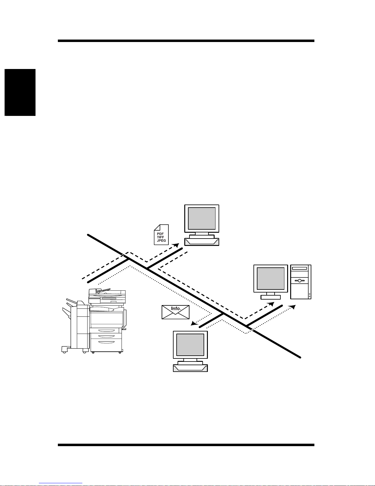
2.1.2 Scan to FTP Server ..........................................2-4
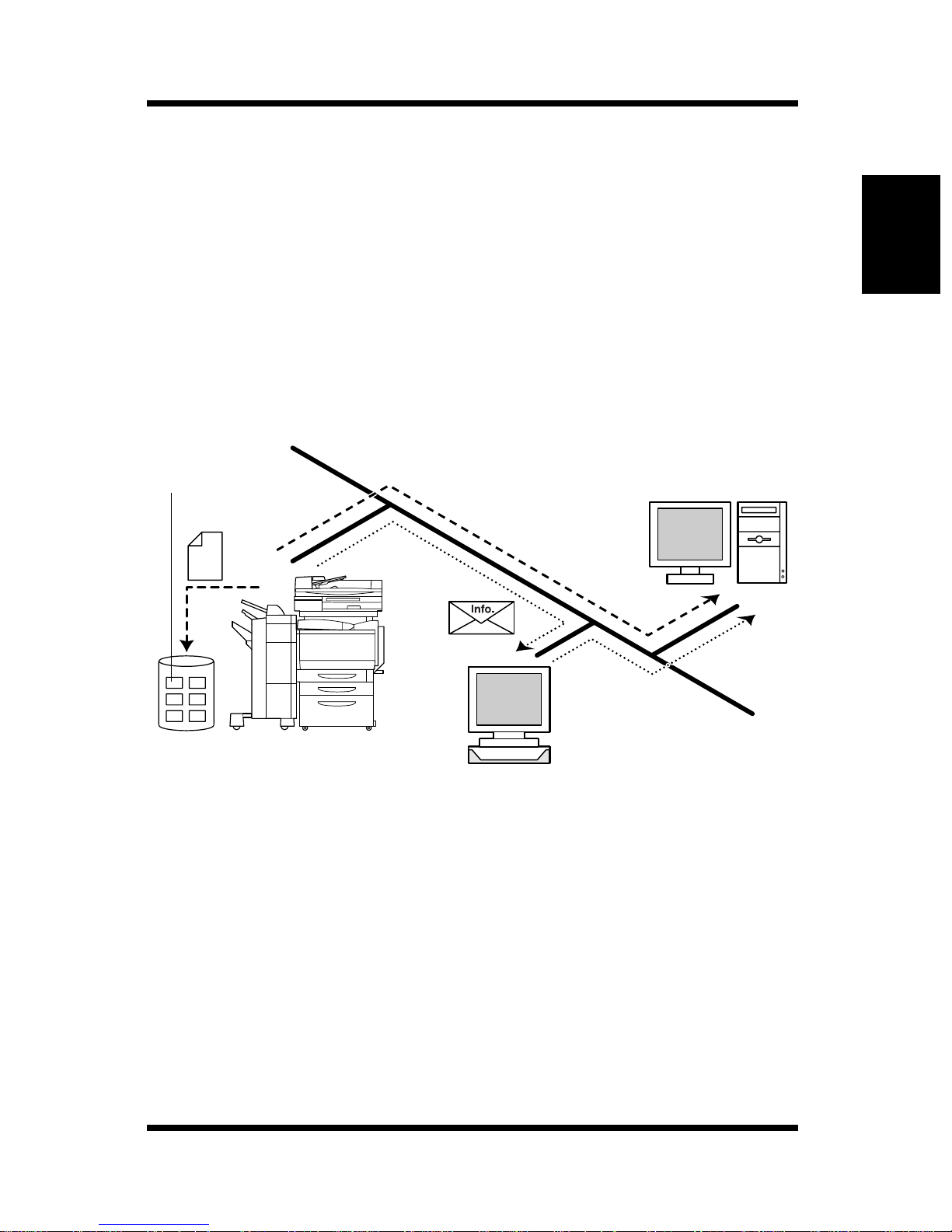
2.1.3 Scan to Mailbox................................................2-5
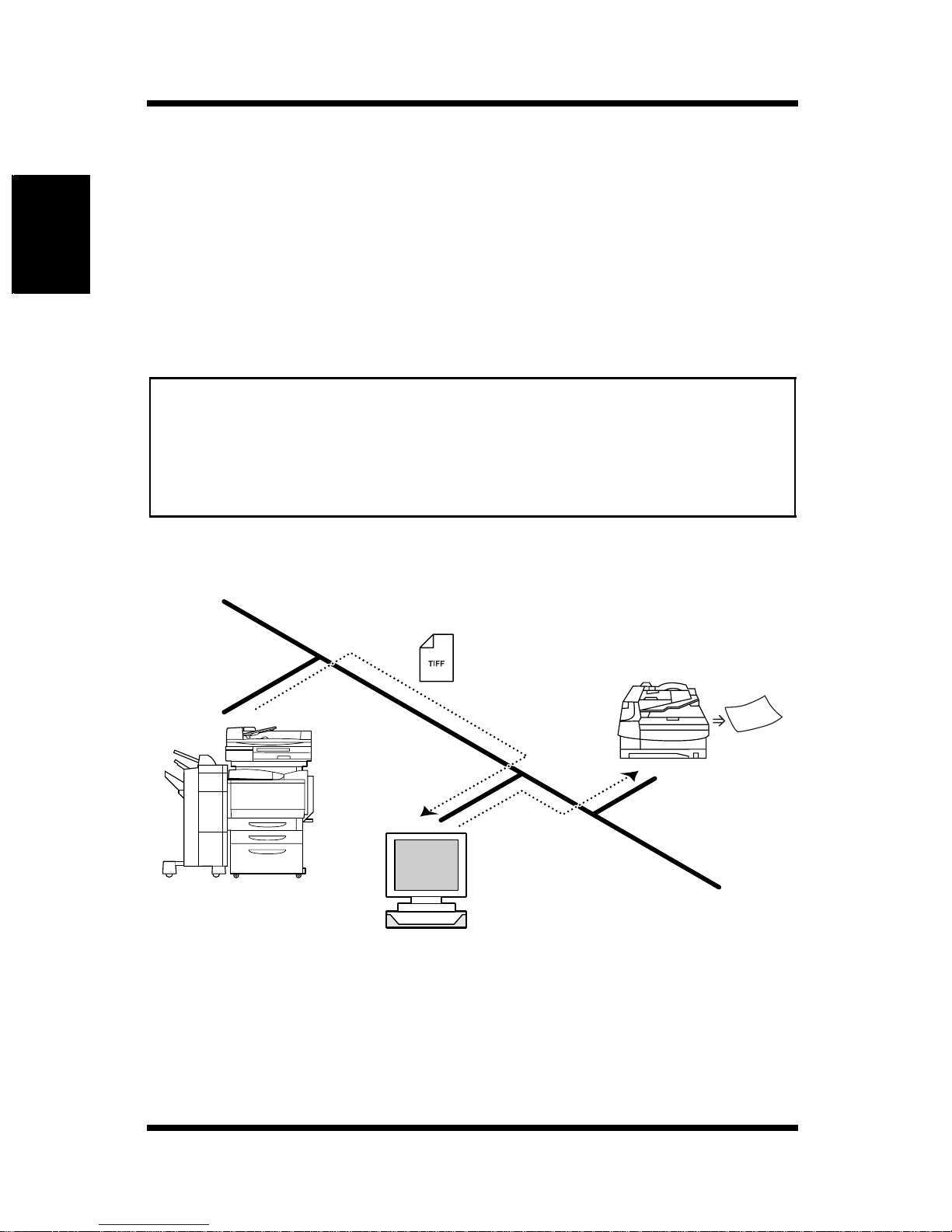
2.1.4 Internet FAX ......................................................2-6
2.1.5 Environment Required for Sending Image
Data....................................................................2-8
ii
Page 4

Contents
2.2 Controller Setup Items ................................ 2-9
2.2.1 Network Protocol Settings...............................2-9
2.2.2 Scan Settings....................................................2-9
2.3 Setup Items for Scanning ......................... 2-11
2.3.1 Entering the Setup Screen ...................... ......2-11
2.3.2 Destination Tab...............................................2-12
2.3.3 Scan Mode Tab ...............................................2-13
2.3.4 Document Set Tab..........................................2-14
2.3.5 Checking the Settings on the Destination
Device..............................................................2-15
2.3.6 Registering the Scan Mode Default
Settings...........................................................2-15
2.4 E-Mail Notification ..................................... 2-16
2.4.1 Notified Information .......................................2-16
2.5 URL Notification ........................... .... ..... .... 2-17
2.6 Entering the Controller Setup Screen ..... 2-18
2.7 Setting the Error Notification
Destination ................................................. 2-18
2.8 Setting the Sender (From) Address ......... 2-19
2.9 Scan to E-Mail Function ............................ 2-20
2.9.1 Setting the Controller.....................................2-21
2.9.2 Retrieving Mails........................................ ......2- 2 2
2.10 Scan to Mailbox Function ......................... 2-23
2.10.1 Setting the Controller.....................................2-24
2.10.2 Creating a Mailbox ...................... ....... ...... ......2-24
2.10.3 Downloading the Image Data to the
Computer ........................................................2-25
iii
Page 5

Contents
2.11 Scan to FTP Server Function ................... 2-26
2.11.1 Enabling the FTP Transfer Function.............2-27
2.11.2 Proxy Settings ................................................2-27
2.11.3 Retrieving the Image Data .............................2-28
2.12 Internet FAX Transmission Function ....... 2-29
2.12.1 Setting the Controller.....................................2-29
2.13 Internet FAX Reception Function ............. 2-30
2.13.1 Setting the Controller.....................................2-30
2.14 Registering the One-Touch Key and
Temporary Registration Key ..................... 2-31
2.14.1 One-Touch Key Registration .........................2-31
2.14.2 Temporary Registration Key Registration....2-38
2.15 Image Data .................................................2-43
2.15.1 File Format......................................................2-43
2.15.2 File Name ........................................................2-44
2.16 Hold Period of the Image Data ................. 2-46
iv
Page 6

Chapter 1
Using Printer Management Utility
Using Printer Management Utility Chapter 1
Page 7

1.1 System Requirements
Printer Management Utility for Fiery X3e 31C-M is a device control utility
program prov ided b y the HTTP serv er built into the Fiery X3e 31C -M (print er
controller). This utility can be used with a Web b rowser as an interface for
remotely controlling Fiery X3e 31C-M.
1.1 System Requirements
The following items are required to use this utility.
Computer
•Software
Operating System Web Browser
Using Printer Management Utility Chapter 1
Windows 98/NT 4.0 Internet Explorer 4 or higher,
Netscape Navigator 4 or higher
Windows Me Internet Explorer 5.5 or higher,
Netscape Navigator 4 or higher
Windows 2000 Internet Explorer 5 or higher,
Netscape Navigator 4 or higher
Windows XP Internet Explorer 6 or higher,
Netscape Navigator 4 or higher
MacOS 9.x Internet Ex plorer 4.5 or higher
Netscape Navigator 4 or higher
MacOS X Internet Ex plorer 5.1 or higher
Netscape Navigator 4 or higher
•Ethernet
• TCP/IP protocol
Digital Copier
Fiery X3e 31C-M printer controller
1-2
Page 8

1.2 Access
1.2 Access
Printer Management Utility can be accessed directly from a Web browser.
1. Start the Web browser.
2. In the Address bar, enter the IP address of the pr inter controller as sho wn
below. Then, press [Enter].
http://<IP address of the printer controller>/
(Example) When the IP address of the printer control ler is 192.168 .0.10:
http://192.168.0.10/
3. The Printer Management Utility screen appears.
1.2.1 Operation
Printer Management Utility operation is identical to that for Internet Web
Using Printer Management Utility Chapter 1
pages. You can click a link on the Web page to jump to the link destination or
click the [Back] or [Forward] button to display the previous or next page.
1-3
Page 9
Using Printer Management Utility Chapter 1
1.3 Screen Configuration
1.3 Screen Configuration
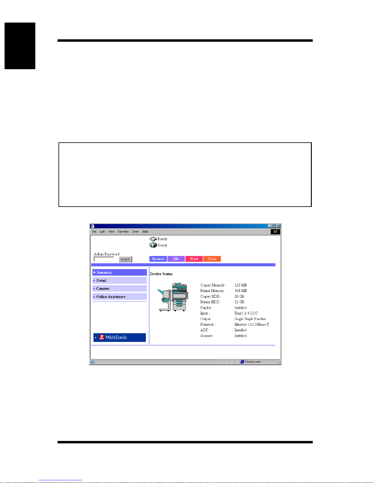
The screen shown below is called the User Mode screen; all users can view
this screen. By entering an appropriate password in the “Admin Password”
box on the User Mode screen, you can enter the Administrator Mode screen.
(See p. 1-6.)
The configuration of the Printer Management Utility screen is shown below.
Note
• Screen images shown in this manual may differ slightly from actual
ones. In addition, specifications are subject to change without prior
notice.
• If you wish to change th e display language of Pri nter Management
Utility, log i nt o th e Adm ini str ato r Mo de , an d ch ang e th e se ttin g usin g the
“Preference” menu.
➀➀➀➀
➁➁➁➁➂
➂
➂➂
➃➃➃➃
➄➄➄➄
➅➅➅➅
Status Display
➀
The current status of the Digital Copier and the printer controller is
indicated by icons and text. The message “Ready” appears when the
Digital Copier and the printer controller are operating normally.
1-4
Page 10

1.3 Screen Configuration
➁ Admin Password
Logs in using the Administrator Mode. (For details on the login
procedure in the Administrator Mode, see “Logging in Using the
Administrator Mode” on page 1 -6.)
➂ Tabs
Selects the category of items to be displayed.
•System
• File
•Print
• Scan
• Network (Administrator Mode only)
For details on each tab, see the following sections.
➃ Menus
Using Printer Management Utility Chapter 1
Selects the information or setup item to be displayed. The menus that
appear vary depending on the tab selection.
For details on each menu, see the following sections.
➄ Information and Setting Details
Displays the details of the selected menu.
➅ WebTools
Moves to the Fiery WebTo ols screen.
1-5
Page 11
Using Printer Management Utility Chapter 1
1.3 Screen Configuration
1.3.1 Logging in Using the Administrator
Mode
By logging into Printer Management Utility in the Adminis tra tor Mo de, you
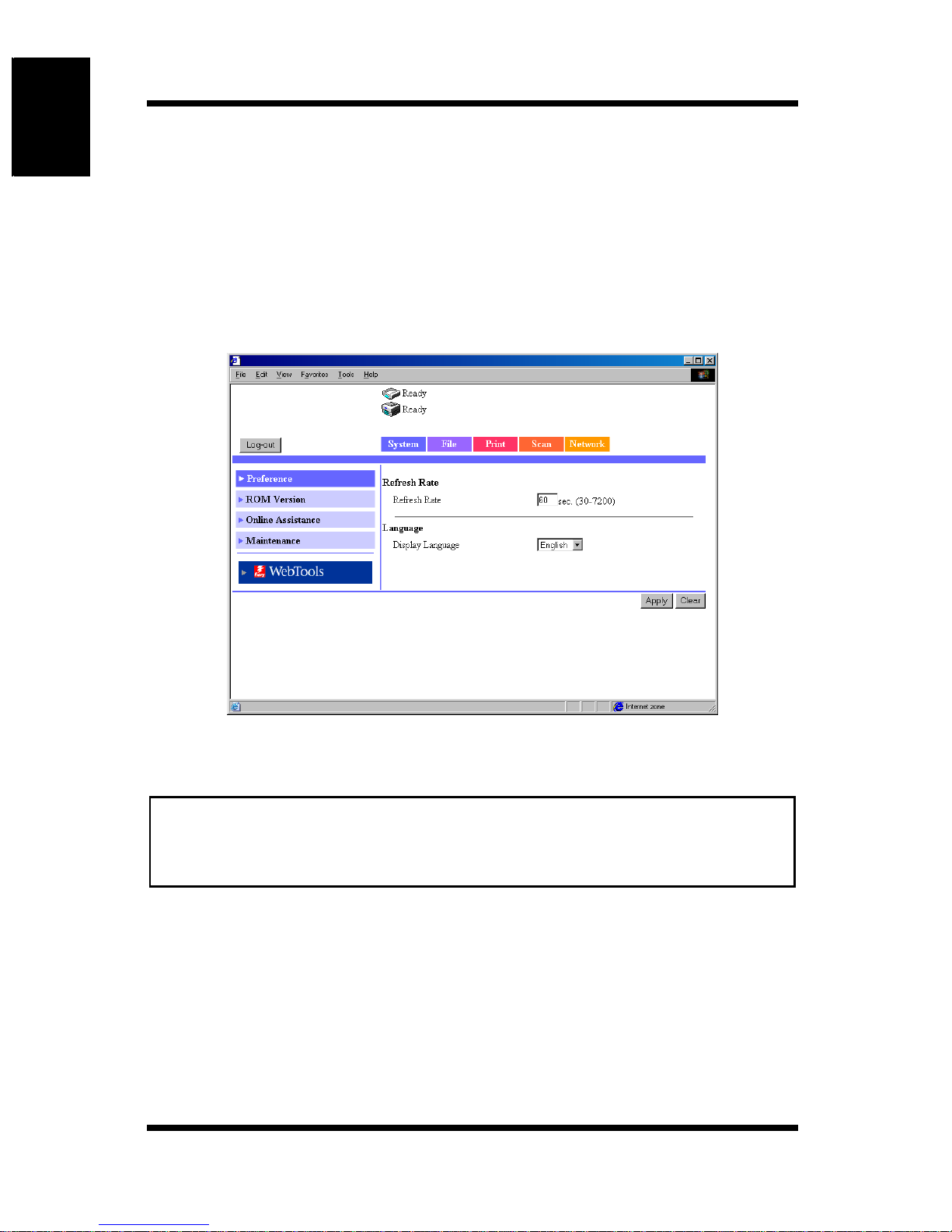
can configure or confirm the printer controller system.
1. Enter the administrator password into the “Admin Password” box at the
upper left corner of the screen.
2. Click [Log-in] to log in using the Administrator Mode.
3. To log out, click [Log-out].
Note
• Fo r th e pa ssword, use the same pas sword as the administ r at or
password for the Digital Copier. For details, consult your copier
administrator.
1-6
Page 12
1.4 User Mode
1.4 User Mode
1.4.1 System Tab
On the [System] tab, information concerning the system configuration of the
Digital Copier and settings are displayed.
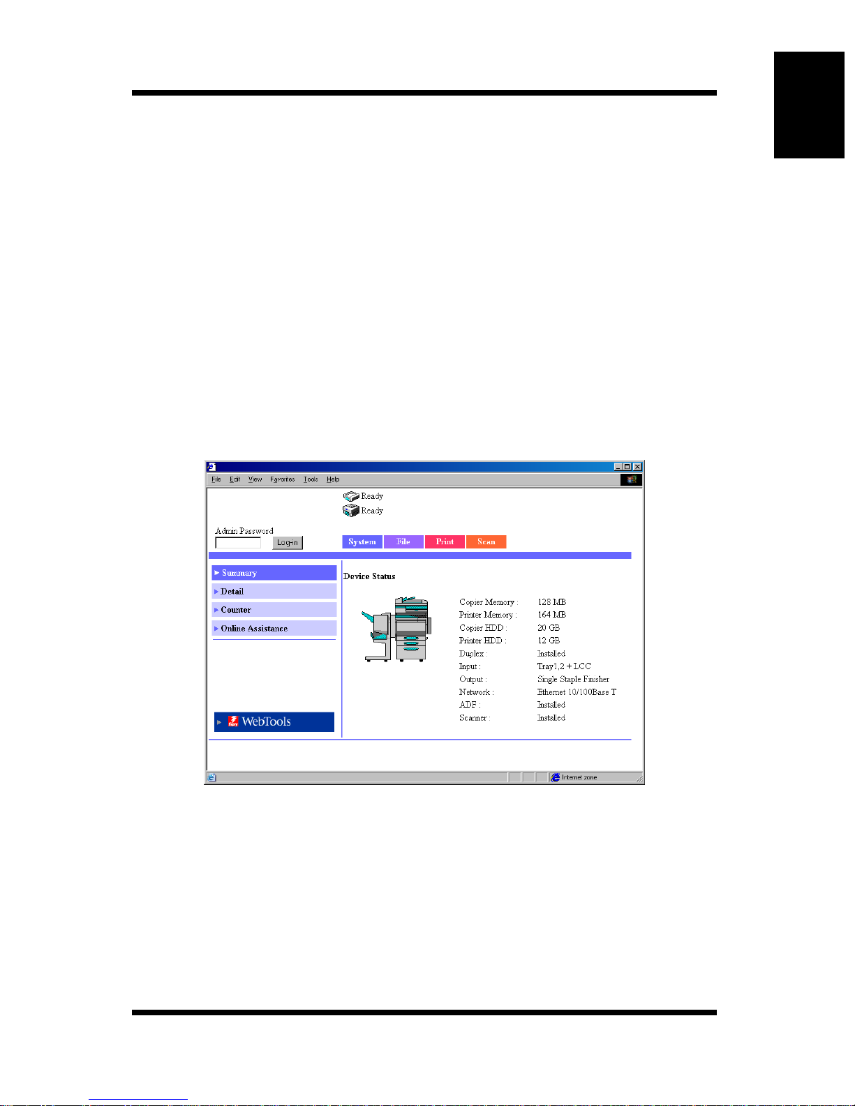
Summary
This screen is the initial screen that appears when you access http://<IP address
of the remote controller>/ with your Web browser. You can also display t he
Summary screen by clicking the [Summary] menu o n th e [System] ta b. The
Summary screen shows the current Digital Copier system configuration and
status.
Using Printer Management Utility Chapter 1
Device Status: Shows the configuration of options installed on the
Installation Status of Options:
Digital Copier using graphics.
Shows the overview of the system configuration of the
Digital Copier.
1-7
Page 13
Using Printer Management Utility Chapter 1
1.4 User Mode
Detail
This screen appears when you click the [Detail] menu on the [System] tab.
Clicking a sub-menu under the [Detail] menu displays infor mat ion abou t the
applicable unit.
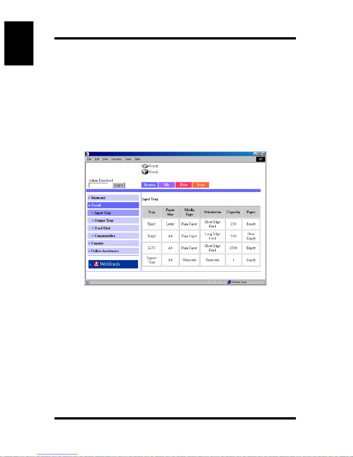
Input Tray
This screen appears when you click the [Input Tray] sub-menu under the
[Detail] menu. It shows the configuration of all the paper feed trays installed
on the Digital Copier.
Tray: Tray name
Paper Size: Size of paper loaded in the tray
1-8
Tray1, Tray2, Tray3, Tray4, LCC, Bypass Tray
(Standard paper size for Europe)
A3, A4, A5, A6, B4, B5, B6, FLS1 (foolscap), FLS2
(folio), FLS3 (G -Le gal), FLS4, 11 × 17, 1 1 × 14, Legal,
Letter, Executive, 5.5 × 8.5, A3Wide, A3Wide+,
Envelope C10, Envelope C5, Envelope DL, Envelope
Monarch
Page 14

(Standard paper size for U.S.A.)
A3, A4, A5, A6, FLS1 (foolscap), FLS2 (folio), FLS3
(G-Legal), FLS4, 11 × 17, 11 × 14, Legal, Letter,
Executive, 5.5 × 8.5, 12.25 × 18, 12 × 18, 4 × 6,
Envelope C10, Envelope C5, Envelope DL, Envelope
Monarch
(Non-standard paper size)
(CD) × (FD) mm, (CD) × (FD) inch
Media Type: Type of media loaded in the tray
Plain Paper, Thick 1, Thick 2, Thick 3, Envelope, OHP,
2nd side Plain Paper, Thick 1 2nd-Side, Thick 2 2ndSide, Thick 3 2nd-Side
In addition, if the sheet properties are specified, the
paper quality type is shown.
Not 2nd side Plain, Recycled Plain, Exclusive
1.4 User Mode
Using Printer Management Utility Chapter 1
Orientation: Orientation of paper loaded in the tray
Long Edge Feed, Short Edge Feed
Capacity: Maximum number of sheets that can be loaded in the
tray
P aper: Amount of paper remaining in the tray
1-9
Page 15
Using Printer Management Utility Chapter 1
1.4 User Mode
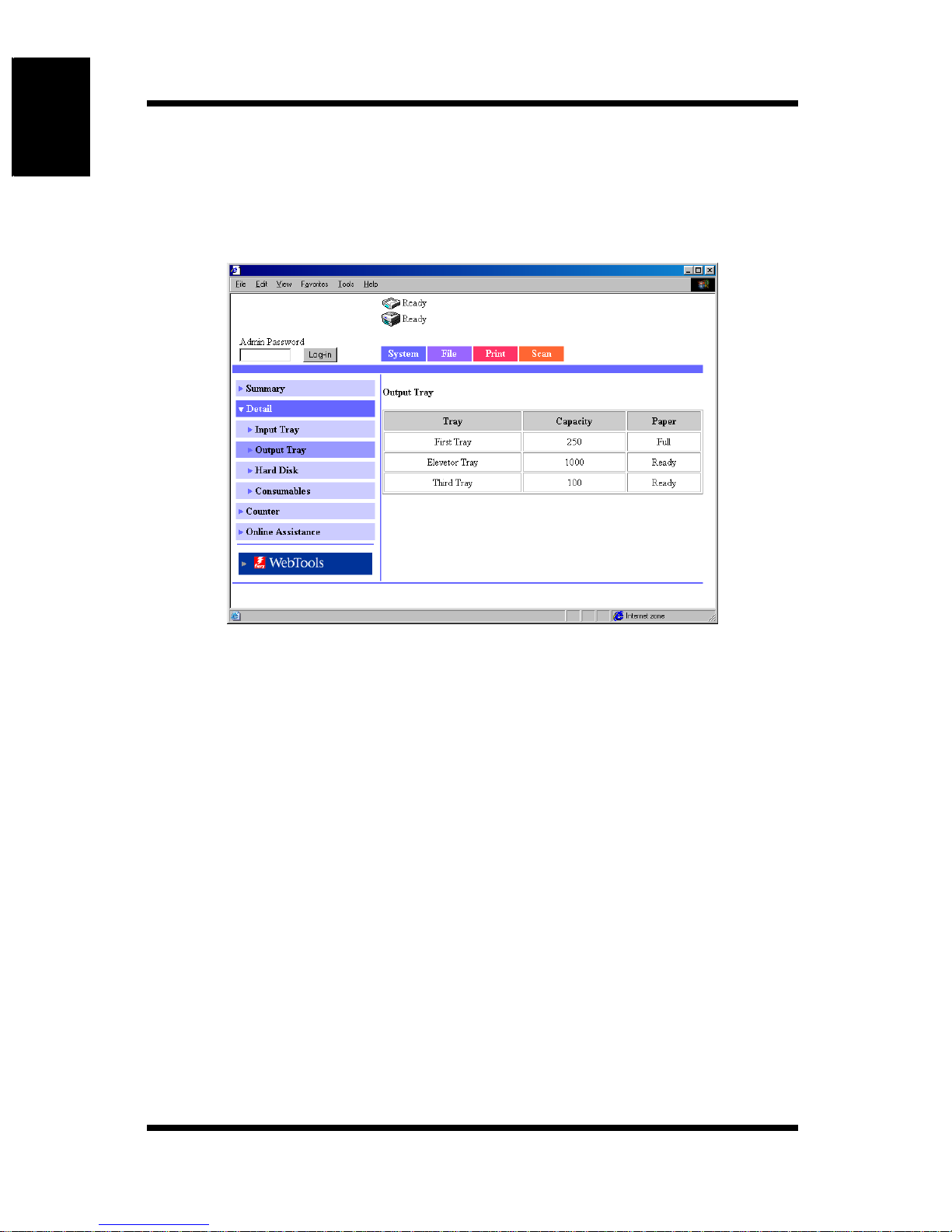
Output Tray
This screen appears when you click the [Output Tray] sub-menu under the
[Detail] menu. It shows the configuration of all the output trays installed on
the Digital Copier.
Tray: Option tray name
(When Staple Finisher is install e d)
First Tray, Elevator Tray, Third Tray
(When Saddle Finisher is installed)
Elevator T r ay, Saddle Tray
Capacity: Maximum number of A4/Letter -size s heets the tray can
hold
P aper: Tray status
1-10
Page 16
1.4 User Mode
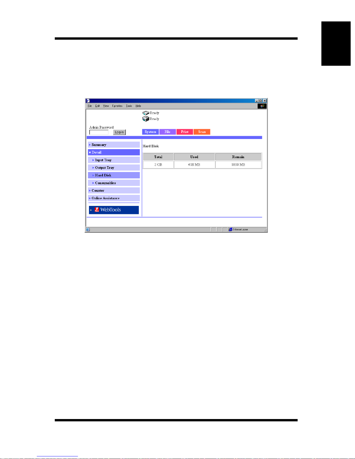
Hard Disk
This screen appears when you click the [Hard Disk] sub-menu under the
[Detail] menu. It shows the status of the hard disk installed on the Digital
Copier.
Using Printer Management Utility Chapter 1
Total: Size of the installed hard disk
Used: Amount of hard disk space used by the system
Remain: Amount of free hard disk space
1-11
Page 17
Using Printer Management Utility Chapter 1
1.4 User Mode
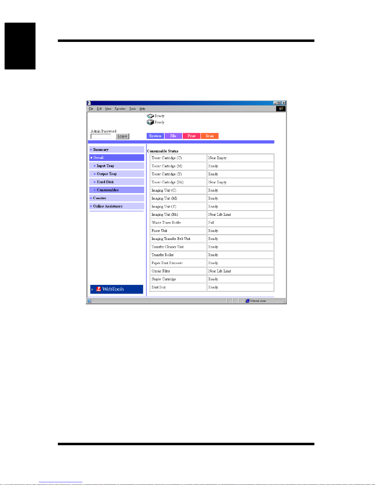
Consumables
This screen appears when you click the [Consumables] sub-menu under the
[Detail] menu. It shows the current status of consumables of the Digital
Copier and the option units.
Toner Cartridge (C, M, Y, Bk):
Imaging Unit (C, M, Y, Bk):
Waste Toner Bottle:
Fuser Unit: Fuser unit information
1-12
Toner cartridge information for each color
Ready, Near Empty, Empty
Imaging unit information for each color
Ready, Near Life Limit, Life Limit
Was te tone r bottle information
Ready, Near Full, Full
Ready, Near Life Limit, Life Limit
Page 18

Imaging Transfer Belt Unit:
Imaging transfer belt unit information
Ready, Near Life Limit, Life Limit
Transfer Cleaner Unit:
Transfer cleaner unit information
Ready, Near Life Limit, Life Limit
Transfer Roller:
Transfer roller unit information
Ready, Near Life Limit, Life Limit
Paper Dust Remover:
Paper dust remover information
Ready, Near Life Limit, Life Limit
Ozone Filter: Ozone filter information
Ready, Near Life Limit, Life Limit
1.4 User Mode
Using Printer Management Utility Chapter 1
Staple Cartridge:
Staple unit information
Ready, Empty
Dust Box: Dust box (box for punch scraps) information
Ready, Full
1-13
Page 19
Using Printer Management Utility Chapter 1
1.4 User Mode
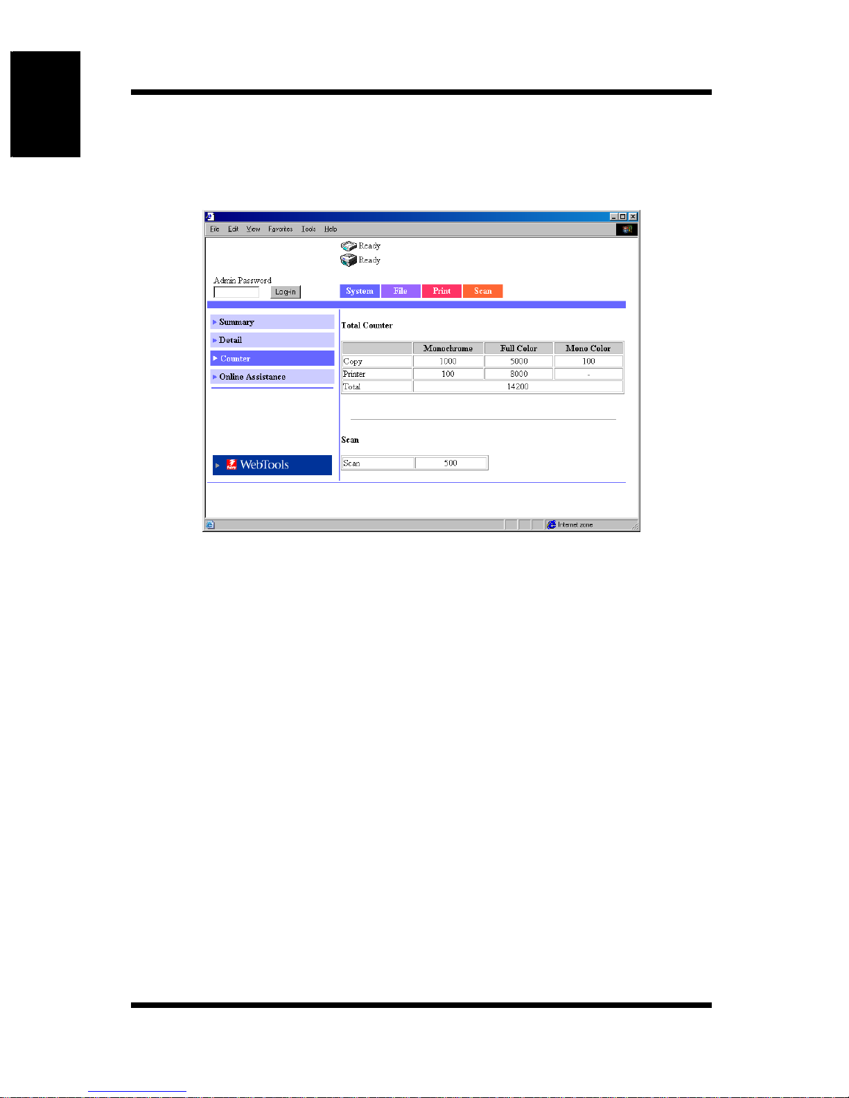
Counter
This screen appears when you click the [Coun ter] menu on the [System] tab. It
shows various counter values that the Digital Copier manages.
1-14
Page 20
1.4 User Mode
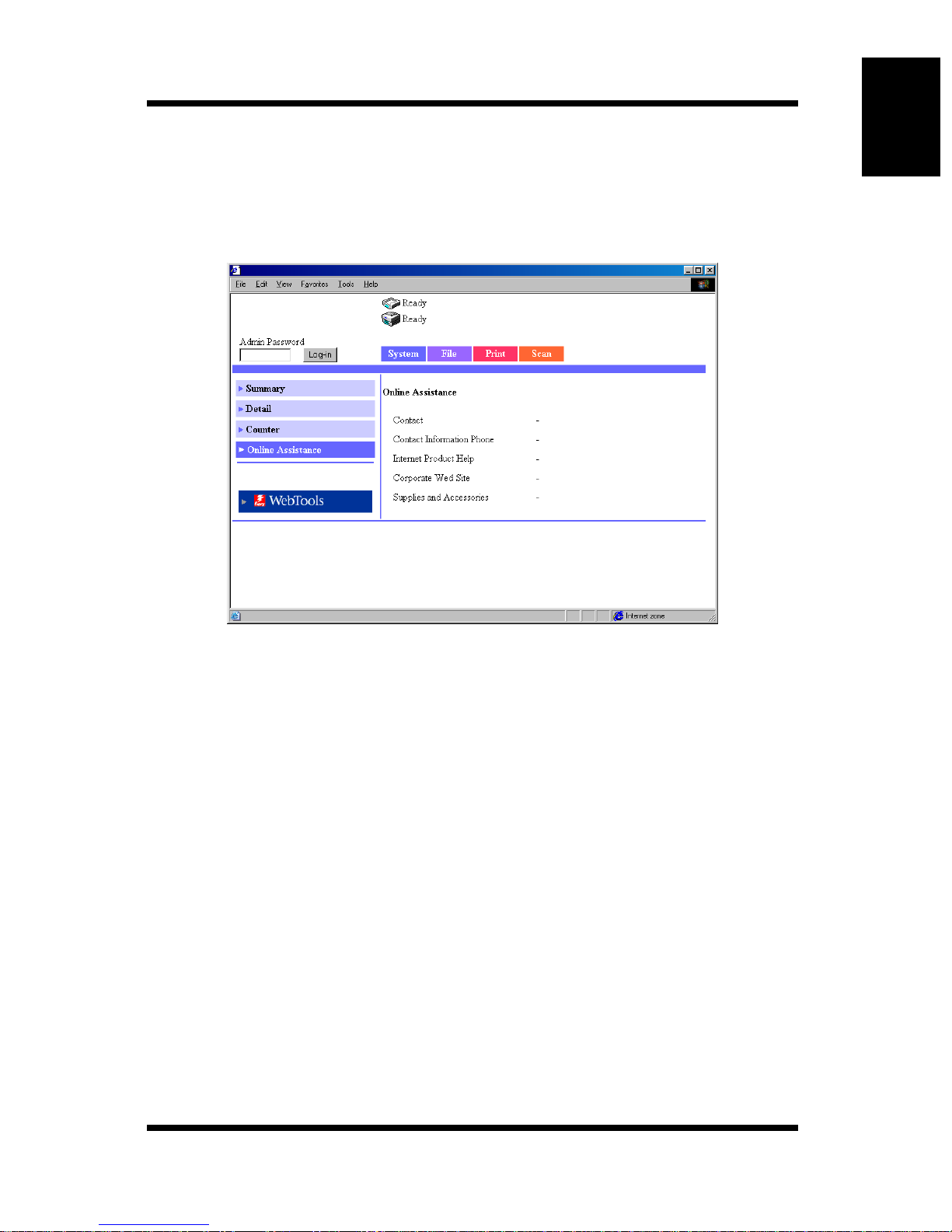
Online Assistance
This screen appears when you click the [Online Assistance] menu on the
[System] tab. It shows information concerning product support. The
information can be edited in the Administrator Mode. (See p. 1-35.)
Using Printer Management Utility Chapter 1
Contact: Support contact for the product (Blank by default)
Contact Information Phone:
Phone number of the support contact for the product
(Blank by default)
Internet Product Help:
The URL of the product information Web site.
Click the URL to jump to the specified Web site.
Corporate Web Site:
The URL of the manufacturer Web site.
Click the URL to jump to the specified Web site.
Supplies and Accessories:
Information about the contact for ordering consumables
(Blank by default)
1-15
Page 21
Using Printer Management Utility Chapter 1
1.4 User Mode
1.4.2 File Tab
The [File] tab is used to manage the mailboxes in the hard disk.
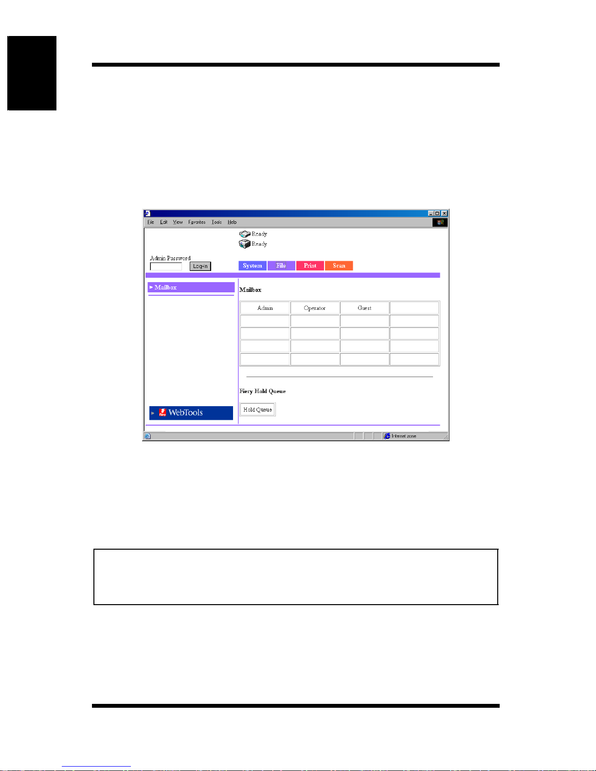
Mailbox
This screen appears when you click the [Mailbox] menu on the [File] tab. It
shows a list of mailboxes in the hard disk.
Mailbox: Click the index to show a list of files in the mailbox.
Hold Queue button:
Shows the Fiery Hold Queue index. Click the button to
show a list of files in the Hold Queue.
Note
• Mailboxes are created in the Administrator Mode. A password is
assigned when a mailbox is created. For details on the password, check
with your administrator.
1-16
Page 22
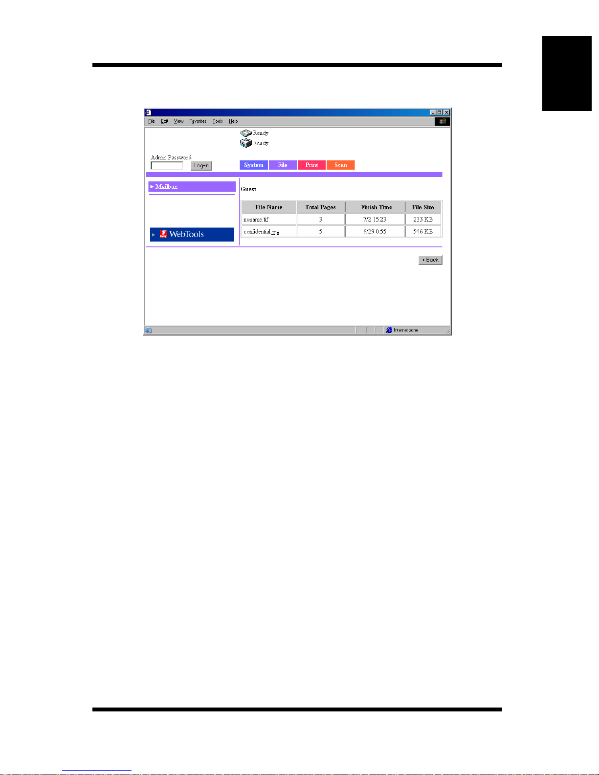
Information on the File List Screen
1.4 User Mode
Using Printer Management Utility Chapter 1
File Name: Name of the file stored in the mailbox.
Total Pages: Total number of pages of the file
Finish Time: Date/Time when the file was stored in the mailbox.
File Size: File size (KB)
[< Back] button: Shows the previous page
1-17
Page 23
Using Printer Management Utility Chapter 1
1.4 User Mode
1.4.3 Print Tab
The [Print] tab is used to configure the printer controller.
Default Setting
This screen appears when you click the [Default Setting] menu on the [Print]
tab. Clicking a s ub-menu under the [Defaul t Setting] m enu displays various
setup screens for the printer.
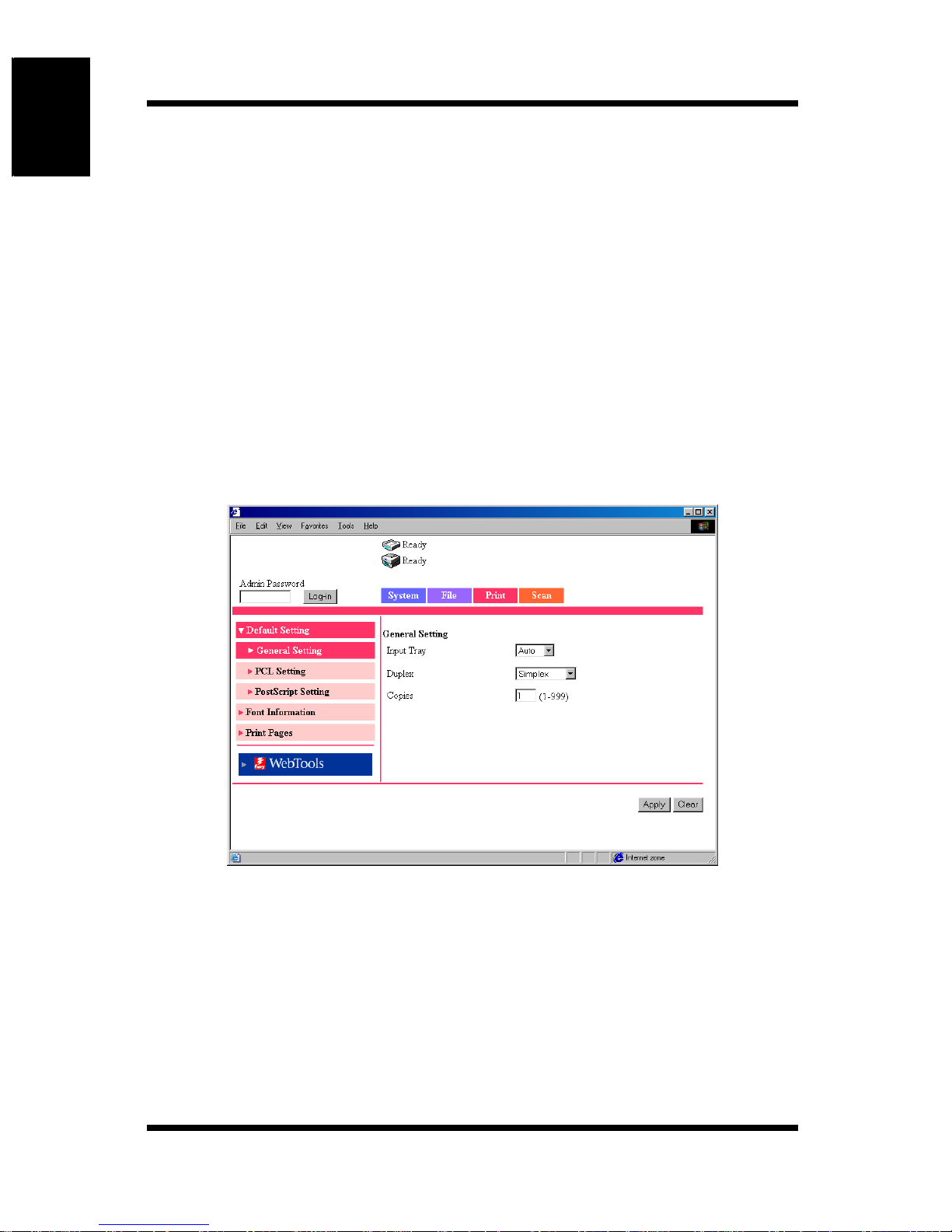
General Setting
This screen appears when you click the [General Setting] sub-menu under the
[Default Setting] menu. The screen is used to specify the default settings of
the paper feed tray, duplex printing, and the number of copies.
Input Tray: From the drop-down list, select the default paper feed
Setting s Auto, Tray1, T ray2, T ray3, Tray4, or LCC
1-18
tray. If the device receives a print job that does not
specify the paper feed tray , the def ault paper feed tray is
used.
Page 24

1.4 User Mode
Duplex: From the drop-down list, select whether to perform
duplex printing by default. If you select duplex
printing, select whether to use long edge binding or
short edge binding. If the device receives a print job
that does not specify the duplex setting, the default
duplex setting is used.
Settings Simplex, Left Binding, or Top Binding
Copies: Enter the default number of copies. If the device
receives a print job that does not specify the number of
copies, the default number of copies is used.
Settings 1 to 999
[Apply] button: Click the button to apply the new settings.
[Clear] button: Click the button to clear the settings that were entered
or selected.
Using Printer Management Utility Chapter 1
1-19
Page 25
Using Printer Management Utility Chapter 1
1.4 User Mode
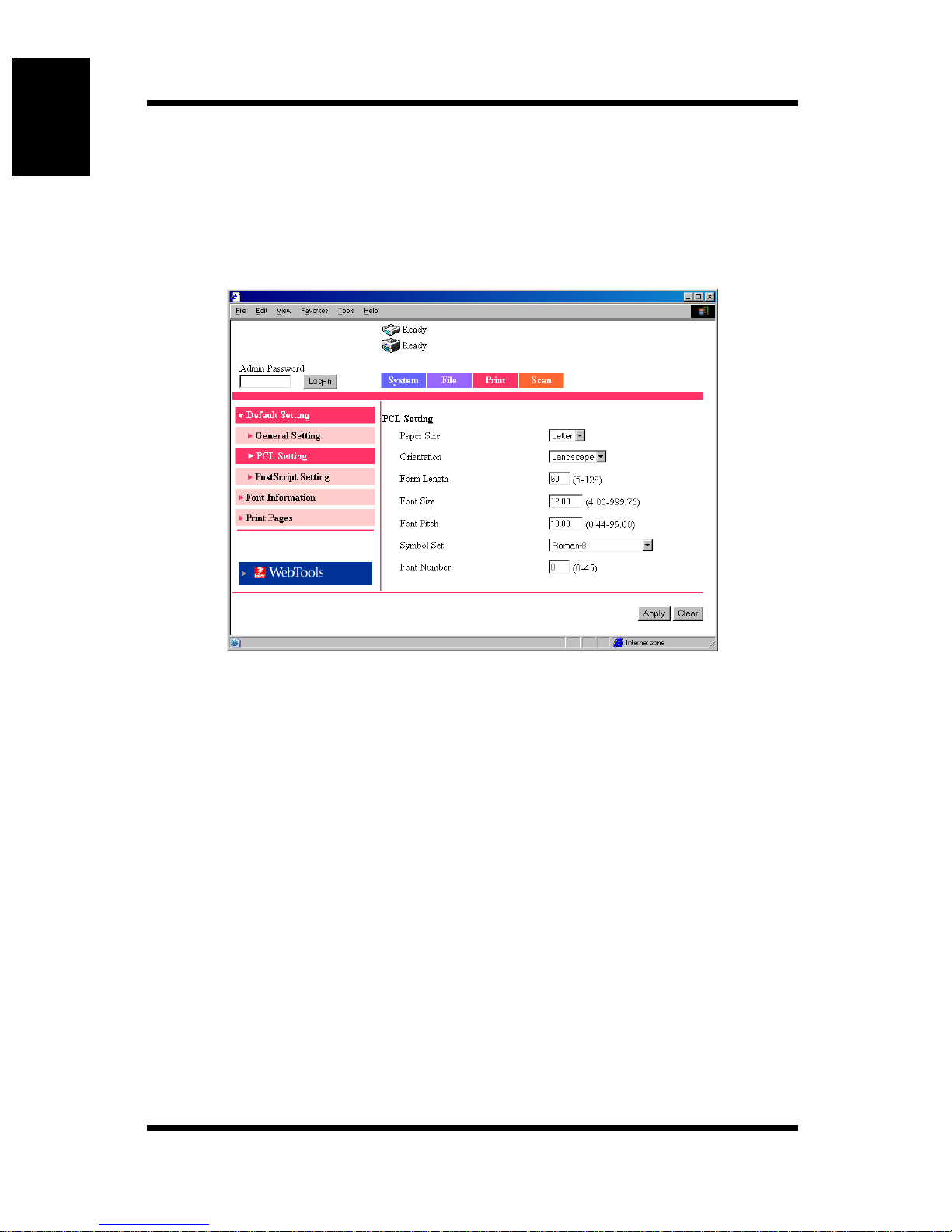
PCL Setting
This screen appears when you click the [PCL Setting] sub-menu under the
[Default Setting] menu. The screen is used to set default values for various
PCL settings. If the page description language that the printer control ler
received is PCL, the settings of the job have precedence.
Paper Size: From the drop-down list, select the default paper size.
Settings Letter, A4
Orientation: From the drop-down list, select the default orientation
of the paper.
Settings Portrait or Landscape
Form Length: Enter the number of lines per page.
Settings 5 to 128
Font Size: Enter the default proportional font size (points).
Settings 4.00 to 999.75 (0.25 steps)
Font Pitch: Enter the number of characters per inch in the
horizontal direction when printing fixed pitch font.
Settings 0.44 to 99.00 (0.01 steps)
1-20
Page 26

1.4 User Mode
Symbol Set: Select the symbol set used by the font. If a symbol set
that cannot be used currently is selected, the default
symbol set is used in its place.
Font Number: Enter the font number.
[Apply] button: Click the button to apply the new settings.
[Clear] button: Click the button to clear the settings that were entered
or selected.
Using Printer Management Utility Chapter 1
1-21
Page 27
Using Printer Management Utility Chapter 1
1.4 User Mode
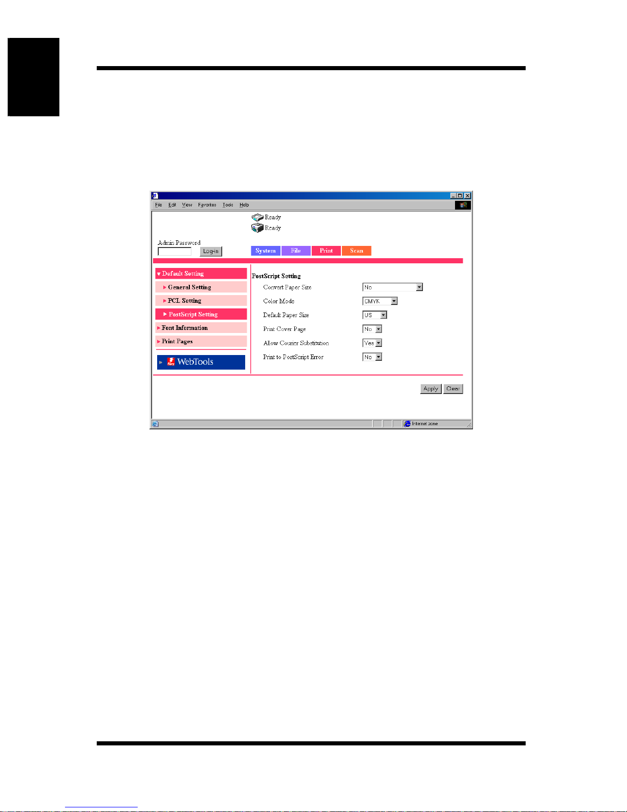
PostScript Setting
This screen appears when you click the [PostScript] Setting sub-menu under
the [Default Setting] menu. The screen is used to set default values for various
PostScript settings. If the page description language that the printer controller
received is PostScript, the settings of the job have precedence.
Convert Paper Size:
Select the setting for automatically converting between
paper sizes using the inch system and those using the
metric system.
Settings No, Letter/11 × 17 to A4/A3, or
A4/A3 to Letter/11 × 17
Color Mode: Select the default color mode.
Settings CMYK or Grayscale
Default Paper Size:
Select the default paper size system.
Settings US or Metric
Print Cover Page:
Select whether to print a cover page by default.
Settings No or Yes
1-22
Page 28

Allow Courier Substitution:
Select whether to automatically substitute Co urier font
by default when the controller receives unsupported
font or unknown font.
Settings No or Yes
(If you select “No”, un supported fonts are not p rinted.)
Print to PostScript Error:
Select whether to print error information by default
when a PostScript error occurs.
Settings No or Yes
1.4 User Mode
Using Printer Management Utility Chapter 1
1-23
Page 29
Using Printer Management Utility Chapter 1
1.4 User Mode
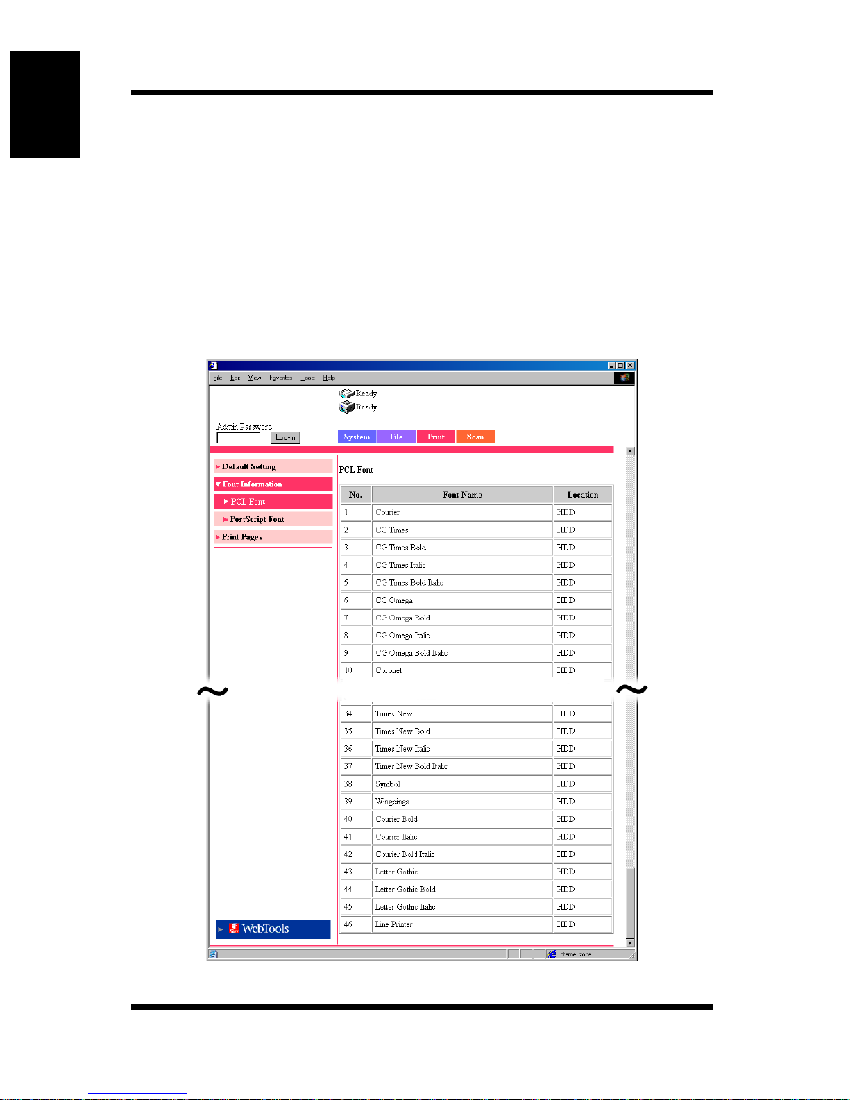
Font Information
This screen appears when you click the [Font Information] menu on the
[Print] tab. It shows a list of PCL fonts and PostScript fonts th at are built into
the printer controller.
PCL Font
This screen appear s wh en yo u cl i ck t he [PC L Font] sub-menu und er t he [Font
Information] menu. It shows a list of PCL fonts that are built into the printer
controller.
1-24
Page 30
1.4 User Mode
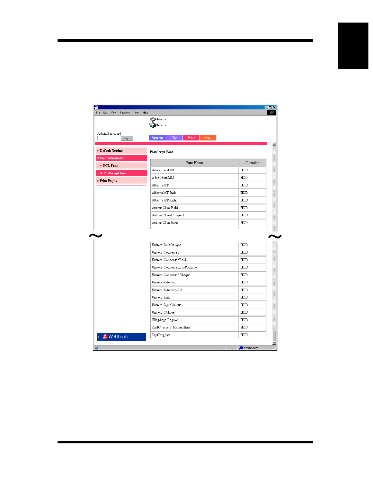
PostScript Font
This screen appears when you click the [PostScript Font] sub-menu under the
[Font Information] menu. It shows a list of PostScript fonts that are built into
the printer controller.
Using Printer Management Utility Chapter 1
1-25
Page 31
Using Printer Management Utility Chapter 1
1.4 User Mode
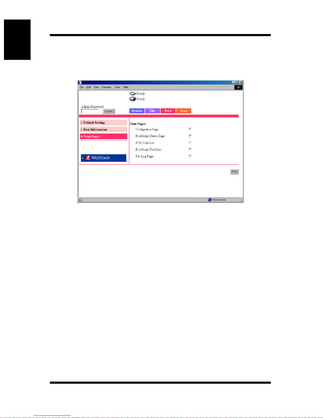
Print Pages
This screen appears when you click the [Print Pages] menu on the [Print] tab.
The screen is used to select the test page to be printed and execute the printing.
Configuration Page:
Select the check box when printing the configuration
page of the printer controller.
PostScript Demo Page:
Select the check box when printing a PostScript demo
page.
PCL Font List: Select the check box when printing the PCL font list.
PostScript Font List:
Select the check box when printing a PostScript font
list.
Job Log Page: Select the check box when printing the job log list.
[Print] button: Click the button to execute the test print.
1-26
Page 32
1.4 User Mode
1.4.4 Scan Tab
The [Scan] tab is used to configure the scanner mode. (For details on the
scanner mode, see chapter 2, “Using the Scanner Mode”.)
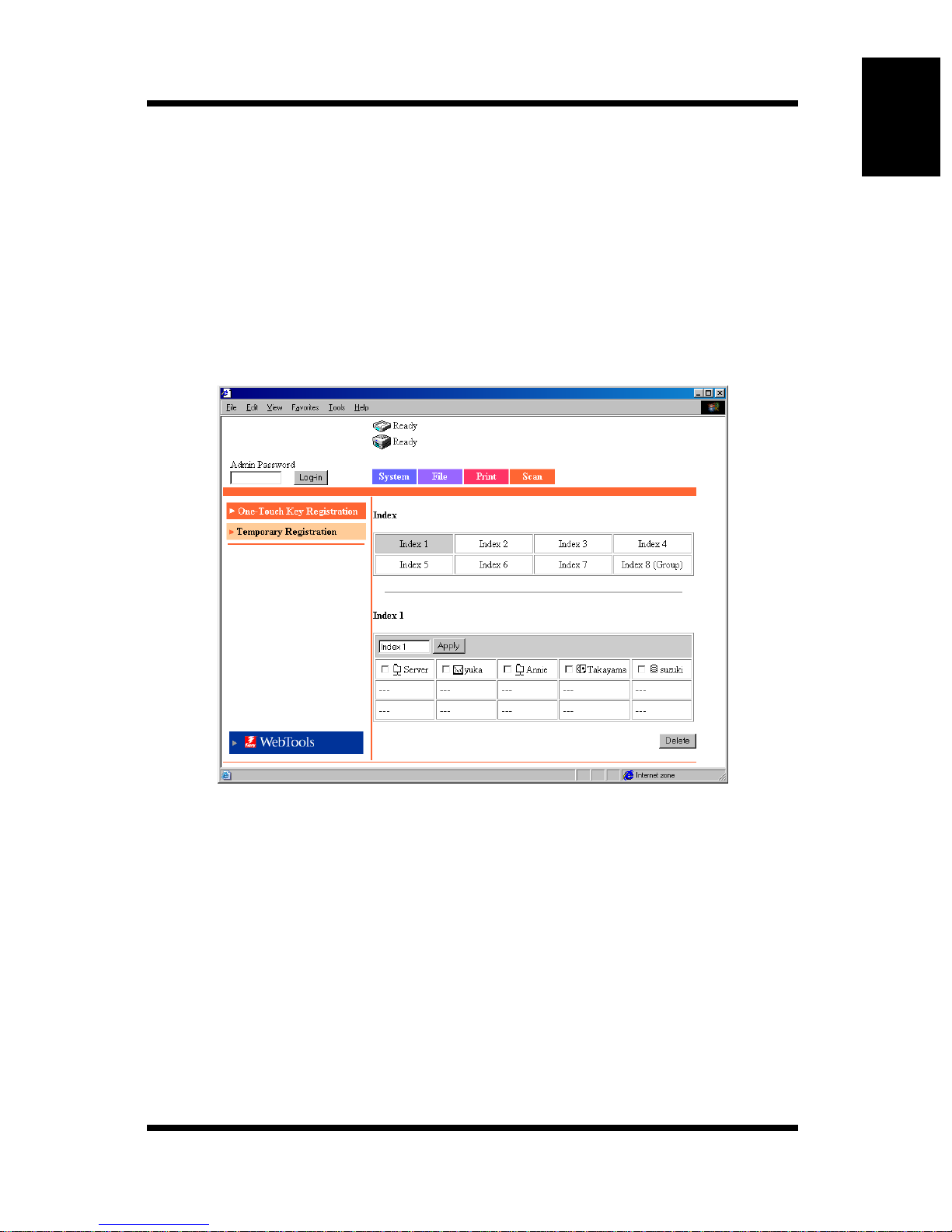
One-Touch Key Registration
This screen appears when you click the [One-Touch Key Registration] menu
on the [Scan] tab. You can use this screen to register the transmission
destination of the scanned data beforehand.
Using Printer Management Utility Chapter 1
Index: Click a preset index name. The destination names that
Index Name: Preset index names are shown in the one-touch list at
are registered in the selected index are displayed at the
lower section of the screen (one-touch list).
the lower section of the screen. You can change the
index name here.
(Enter up to 10 characters.)
1-27
Page 33
1.4 User Mode
Transmission Method:
The transmission method for the registered destination
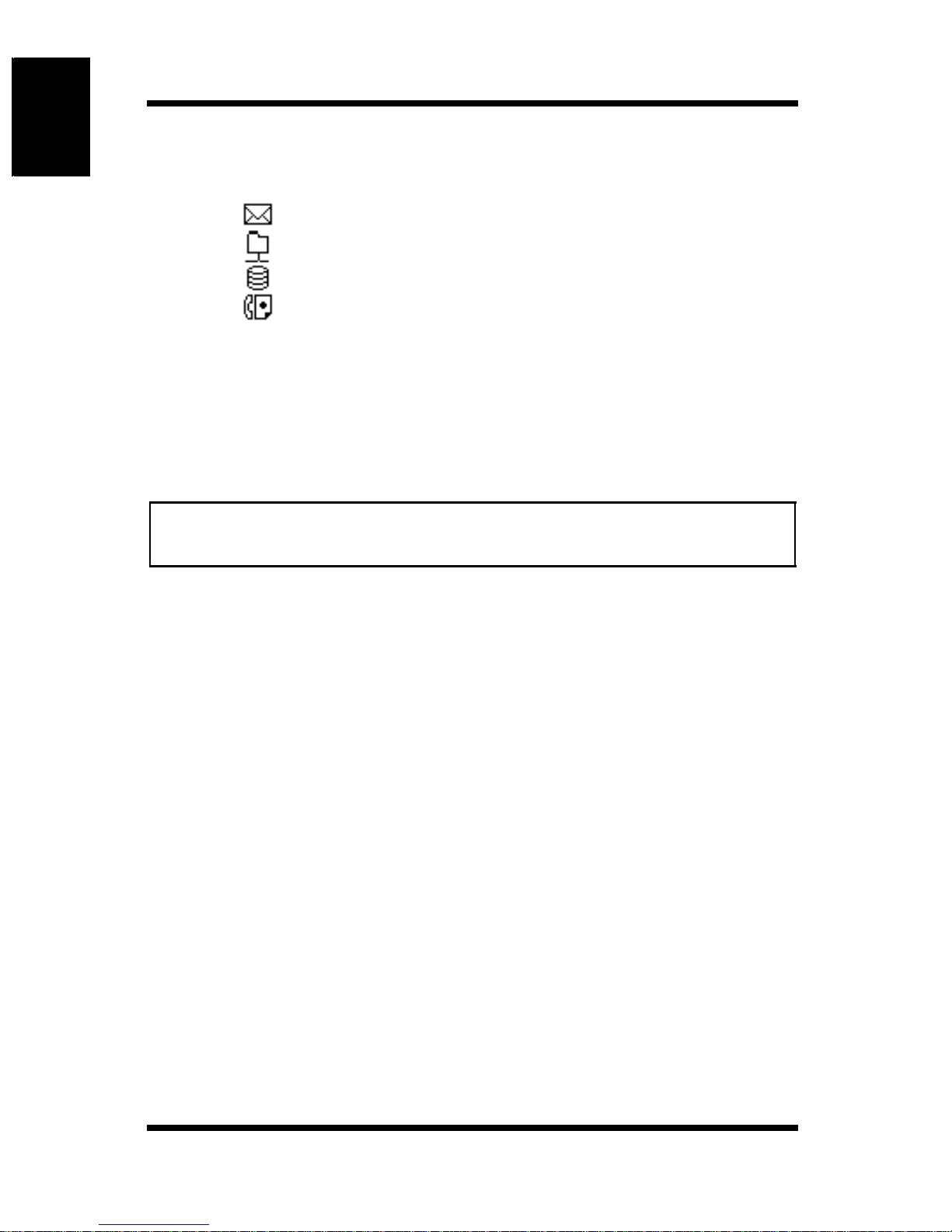
names is shown using icons.
: Scan to E-mail icon
: Scan to FTP Server icon
: Scan to Mailbox icon
: Internet FAX icon
[Apply] button: Click the button to register the index name that you
entered.
[Delete] button: Select the check boxes at the left of the destination
names and click this button to clear the selected
destination names from th e index.
Using Printer Management Utility Chapter 1
Note
• The group registration of destination names for Scan to E-mail and
Internet FAX is valid only on [Index 8].
1-28
Page 34
1.4 User Mode
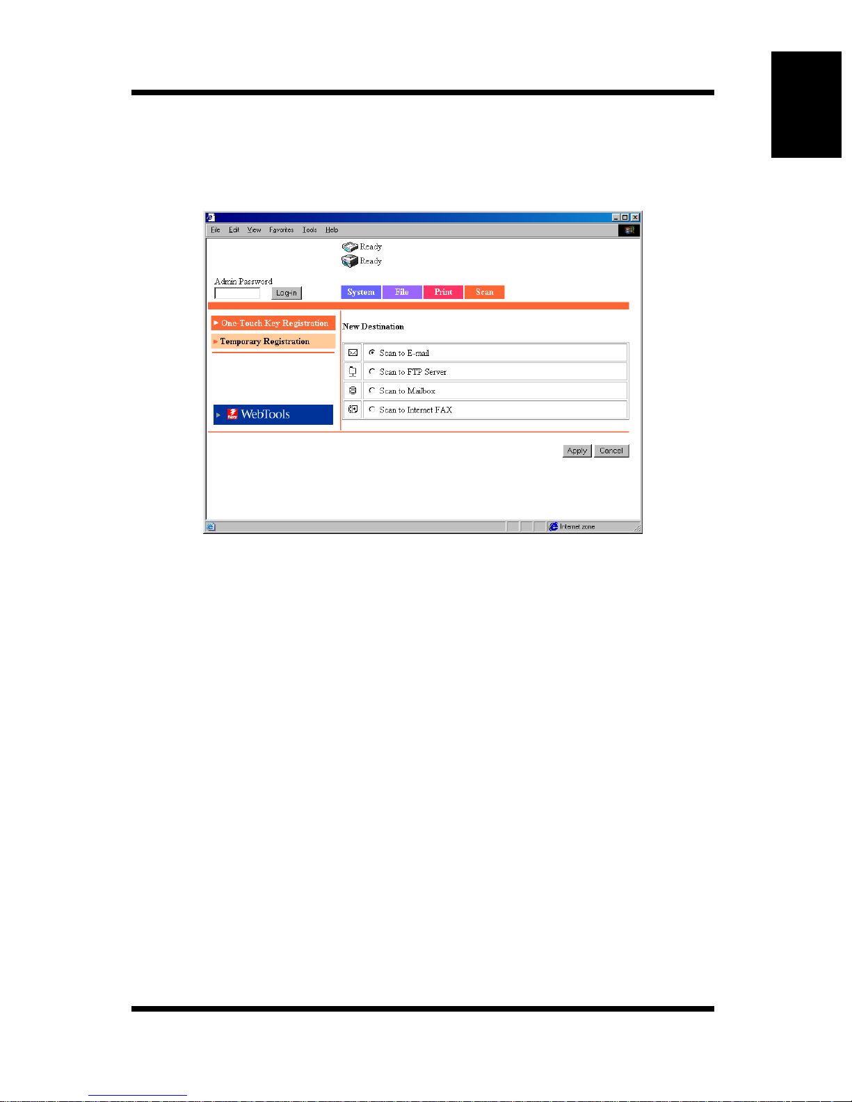
Registering a New Destination
Click an unregistered box (---) in the one-touch list at the lower section of the
screen to display a registration screen for a new destination.
Using Printer Management Utility Chapter 1
Click the transmission method for the recipient.
• Scan to E-mail (
• Scan to FTP Server (
• Scan to Mailbox (
• Scan to Internet FAX (
Click the [Cancel] button to return to the previous screen.
☞
p. 2-33, p. 2-37)
☞
p. 2-34)
☞
p. 2-35)
☞
p. 2-36, p. 2-37)
Changing the Setting of a Registered Destination
Click the destination name you wish to change from the one-touch list at the
lower section of the screen to display a screen used to register or change the
recipient information.
1-29
Page 35
Using Printer Management Utility Chapter 1
1.4 User Mode
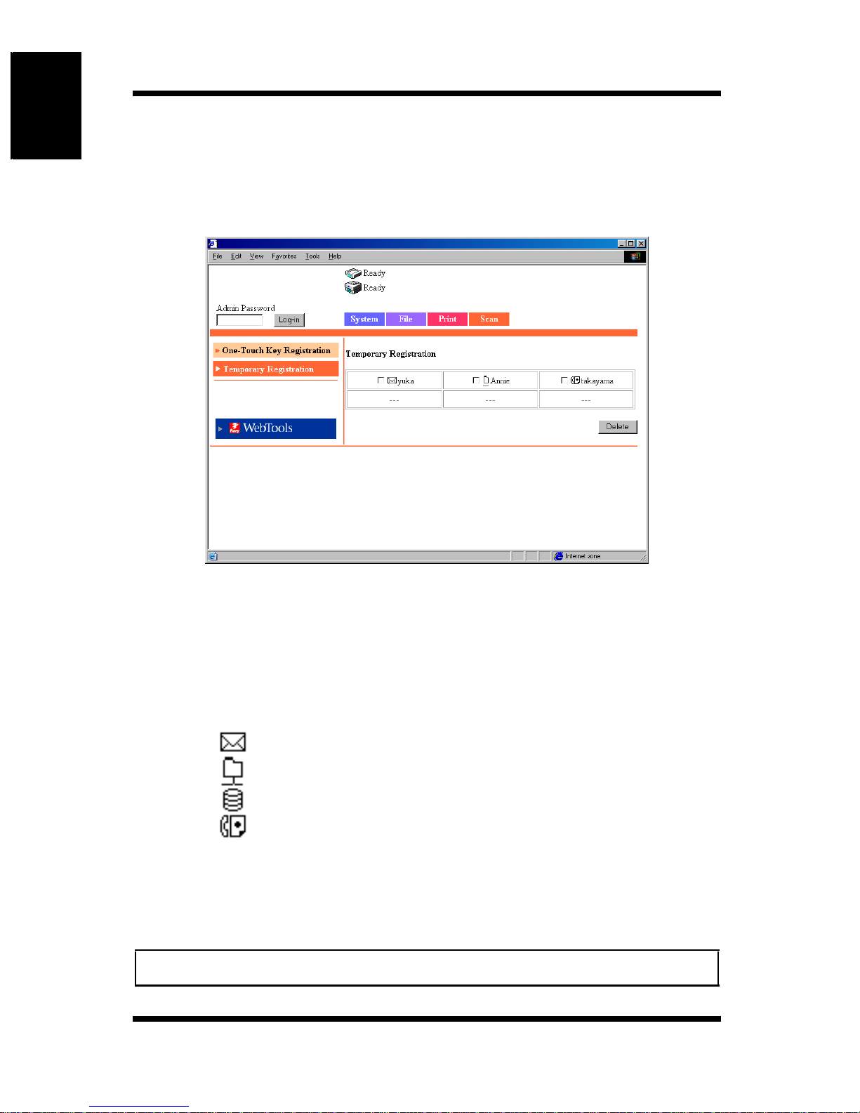
Temporary Registration
This screen appears when you click the [Temporary Registration] men u on the
[Scan] tab. You can use this screen to register the transmission destination and
settings for the scan data used only for a single job.
Temporary Registration Name:
Click a preset name to display a setup confirmation
screen.
Transmission Method:
The transmission method of the registered destination
names is shown using icons.
: Scan to E-mail icon
: Scan to FTP Server icon
: Scan to Mailbox icon
: Internet FAX icon
[Delete] button: Select the check boxes at the left of the names and click
this button to clear the selected temporary registration
names.
Note
• The temporary registration is cleared when the job is executed.
1-30
Page 36
1.4 User Mode
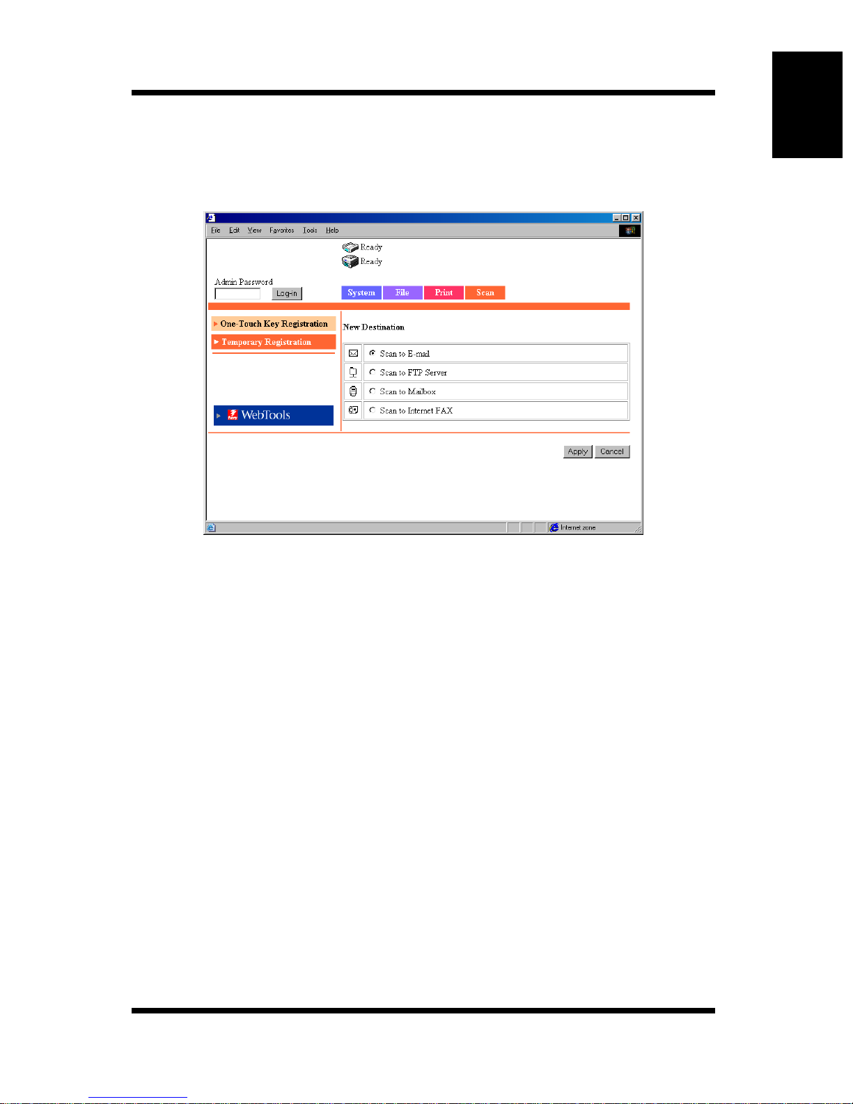
Registering a New Setting
Clicking an unregistered box (---) on the Temporary Registration screen
display a new registration screen.
Using Printer Management Utility Chapter 1
Click the transmission method.
• Scan to E-mail (
• Scan to FTP Server (
• Scan to Mailbox (
• Scan to Internet FAX (
Click the [Cancel] button to return to the previous screen.
☞
☞
p. 2-39)
☞
p. 2-41)
p. 2-41)
☞
p. 2-42)
Confirming the Setting of a Registered Destination Name
Click a name from the Temporary Registration screen to display a setup
confirmation screen.
[< Back] button: Click the button to change the settings to the entered or
selected values and return to the previous screen.
1-31
Page 37
Using Printer Management Utility Chapter 1
1.5 Administration Mode
1.5 Administration Mode
By logging into Printer Management Utility in the Adminis tra tor Mo de, you
can configure or confirm the printer controller system.
For details on the login pro cedure in the Adminis trator Mode, see “Loggi ng in
Using the Administrator Mode” on page 1-6.
1.5.1 System Tab
On the [System] tab, information concerning the system configuration of the
Digital Copier and settings are displayed.
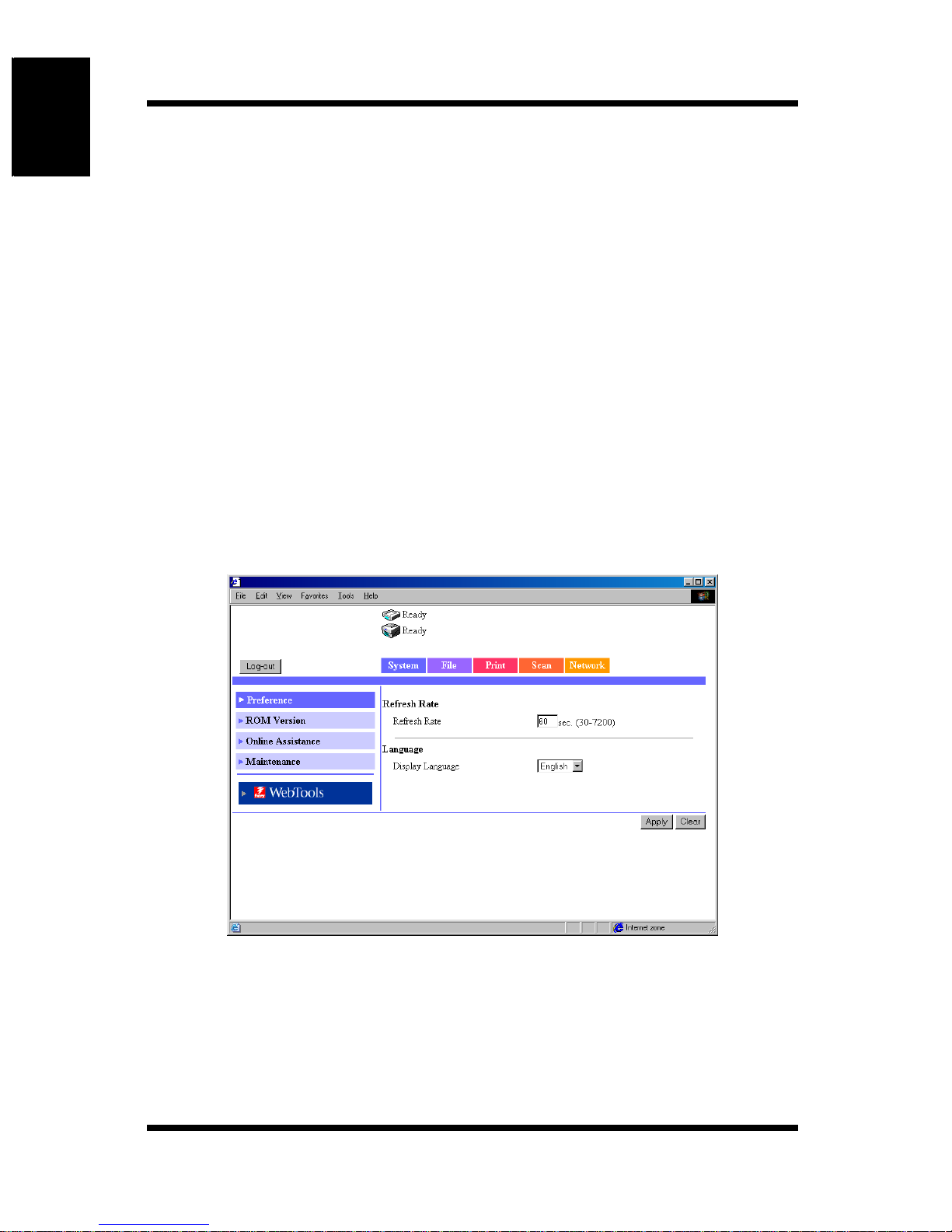
Preference
This screen appears when you click the [Preference] menu on the [System]
tab. The screen is used to specify settings concerning the screen display.
Refresh Rate: Sets the refresh rate of Printer Management Utility.
Settings 30 to 7200 sec.
Display Language:
1-32
Sets the display language of Printer Management
Utility.
Page 38

1.5 Administration Mode
[Apply] button: Click the button to apply the new settings.
[Clear] button: Click the button to clear the settings that were entered
or selected.
Using Printer Management Utility Chapter 1
1-33
Page 39
Using Printer Management Utility Chapter 1
1.5 Administration Mode
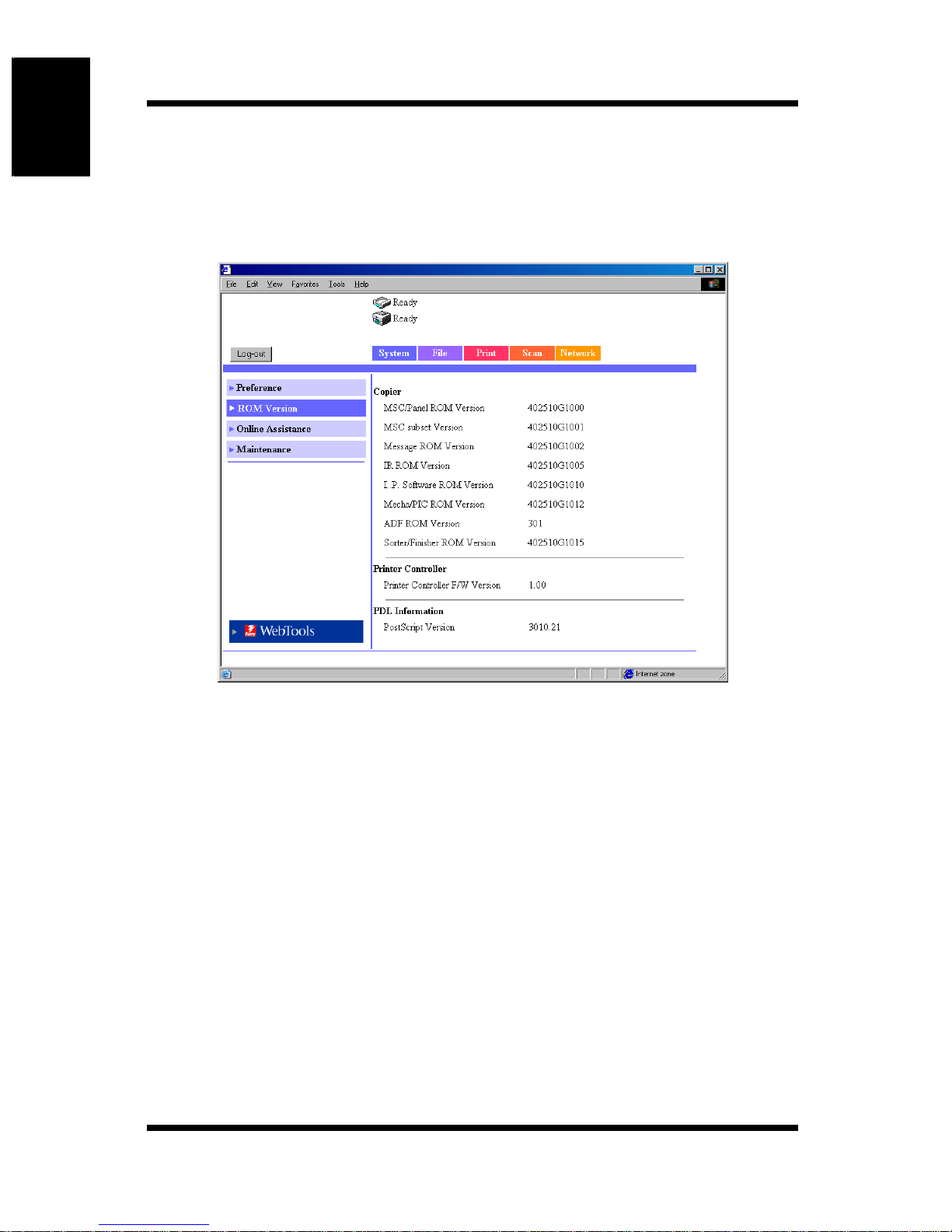
ROM Vers ion
This screen appears when you click the [R OM Version] menu on the [System]
tab. It shows the ROM version of the copier, the firmware version of the
controller, and other information.
Copier
MSC/Panel ROM Version
MSC subset Ve rsi on
Message ROM Version
IR ROM Version
I..P. Software ROM Version
Mecha/PIC ROM Version
ADF ROM Vers ion
Sorter/Finisher ROM Version
Printer Controller
Printer Controller F/W Version
PDL Information
PostScript Version
1-34
Page 40
1.5 Administration Mode
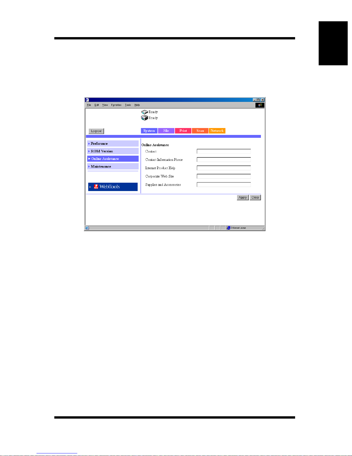
Online Assistance
This screen appears when you click the [Online Assistance] menu on the
[System] tab. You can use the screen to enter information concerning product
support.
Using Printer Management Utility Chapter 1
Contact: Enter the support contact for the product.
Contact Information Phone:
Enter the phone number of the support contact for the
product.
Internet Product Help:
The URL of the product information We b site. ( Can be
changed.)
Corporate Web Site:
The URL of the manufacturer Web site. (Can be
changed.)
Supplies and Accessories:
Enter the contact for ordering consumables.
[Apply] button: Click the button to apply the new settings.
[Clear] button: Click the button to clear the settings that were entered
or selected.
1-35
Page 41
Using Printer Management Utility Chapter 1
1.5 Administration Mode
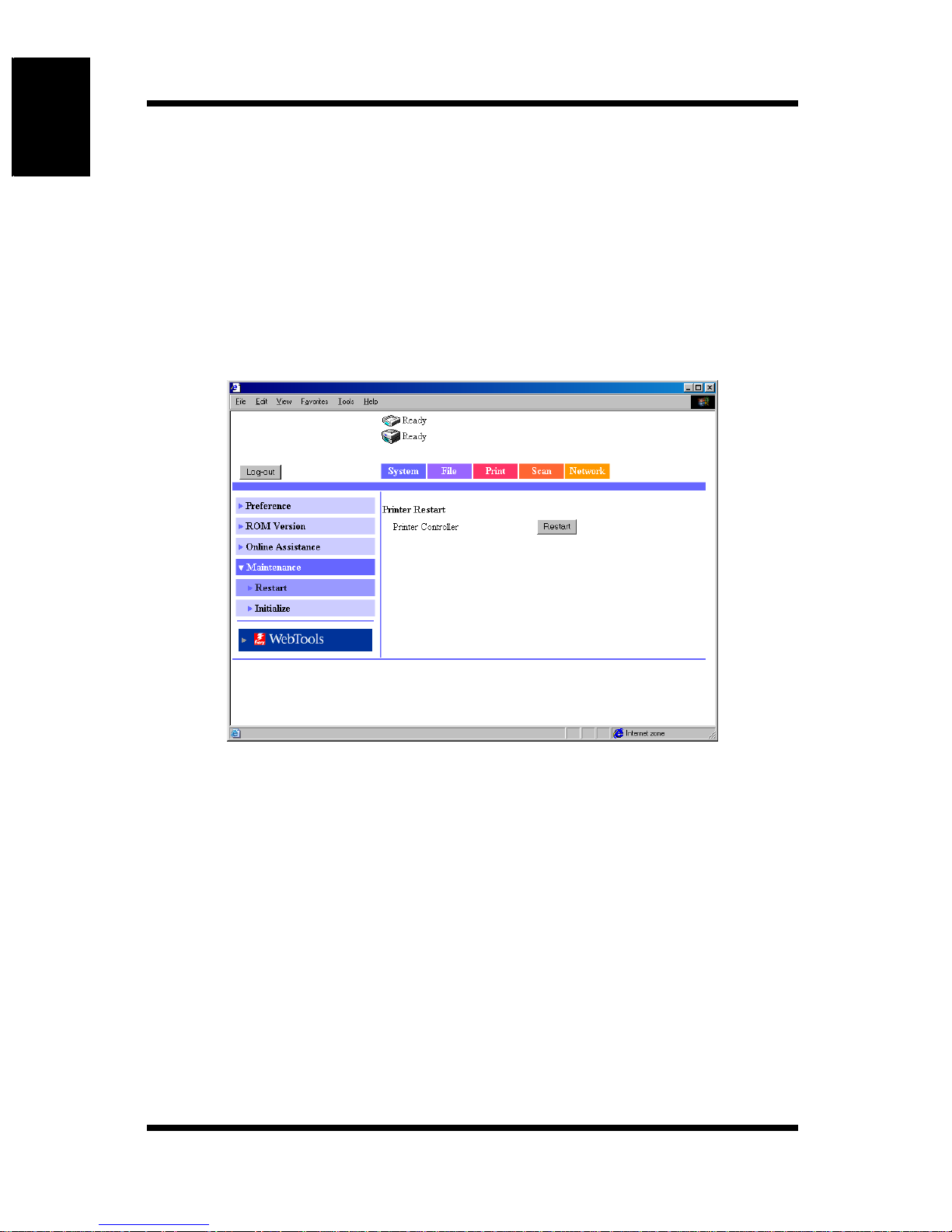
Maintenance
This screen appears when you click the [Maintenance] menu on the [System]
tab. You can use the screen to restart the prin ter con troller o r initialize the
settings (reset to factory default settings).
Restart
This screen appears when you click the [Restart] sub-menu under the
[Maintenance] menu. You can use the screen to restart the printer controller.
Printer Contro ller /[Res tart] button:
1-36
Restarts the printer controller. Click the [Restart] button
to show a screen u sed to conf irm whether to ex ecute the
restart operation. Click the [Yes] button on the
confirmation screen to restart the printer controller.
Page 42
1.5 Administration Mode
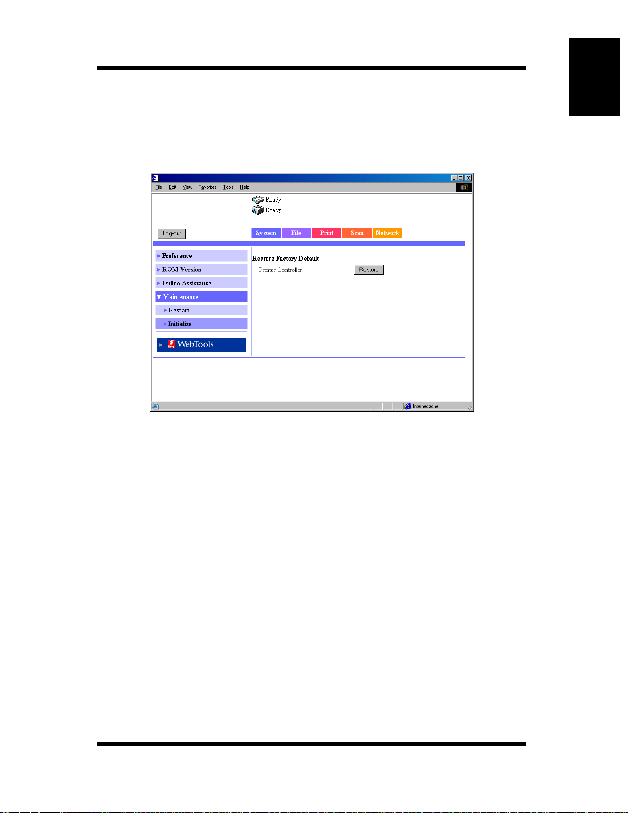
Initialize
This screen appears when you click the [Initialize] sub-menu under the
[Maintenance] menu. You can use the screen to initialize the printer controller
settings (reset to factory default settings).
Using Printer Management Utility Chapter 1
Printer Controller/[Restore] button:
Resets the printer controller settings to factory default.
Click the [Restore] button to show a screen used to
confirm whether to execute the initialization. Click the
[Yes] button on the confirmation screen to reset the
printer controller settings to factory default.
1-37
Page 43
Using Printer Management Utility Chapter 1
1.5 Administration Mode
1.5.2 File Tab
The [File] tab is used to manage the mailboxes in the hard disk.
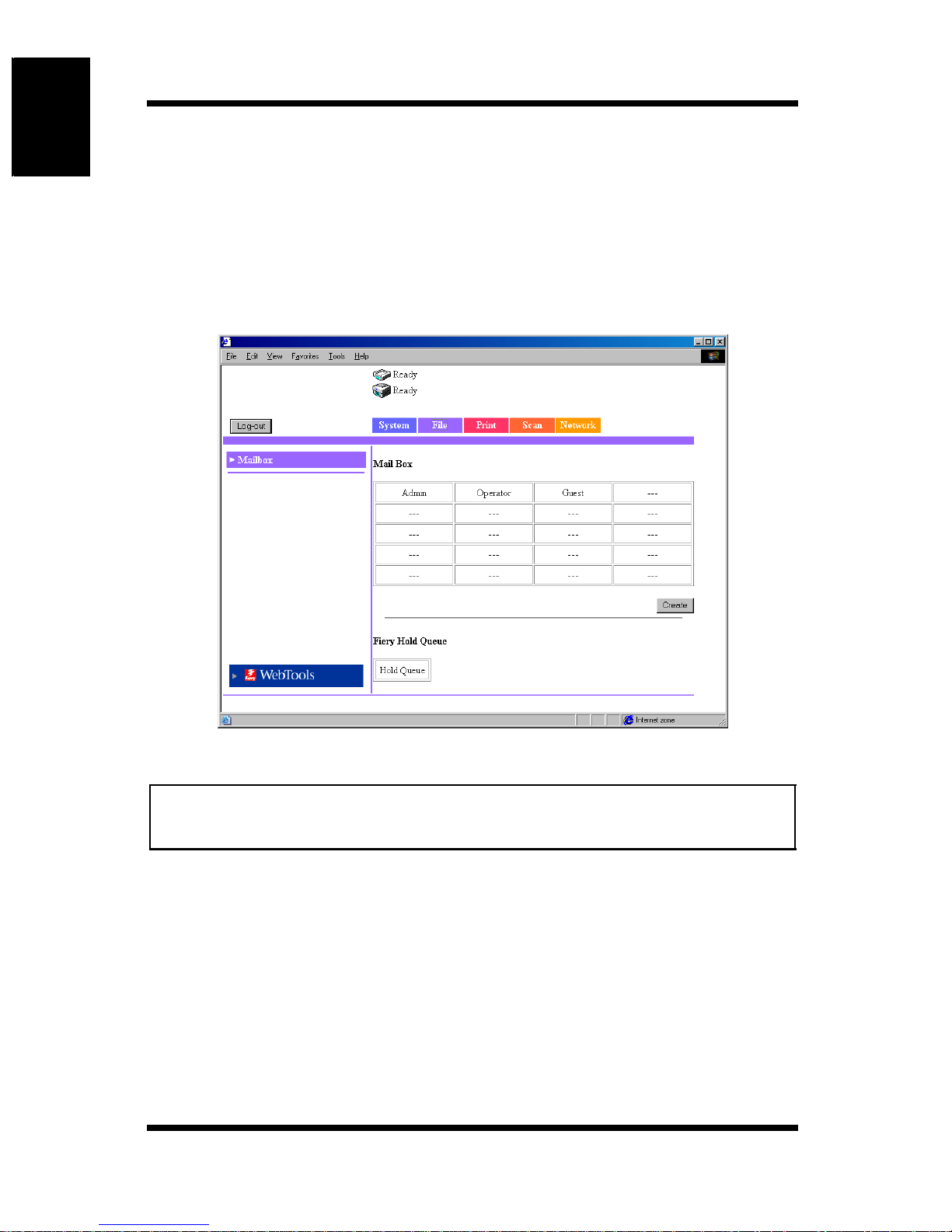
Mailbox
This screen appears when you click the [Mailbox] menu on the [File] tab. It
shows a list of mailboxes in the hard disk.
Note
• The operation is similar to that of the mailboxes of the User Mode. See
“Mailbox” on page 1-16.
[Create] button: Click the b utton to display a screen used to create a ne w
1-38
mailbox.
Page 44
1.5 Administration Mode
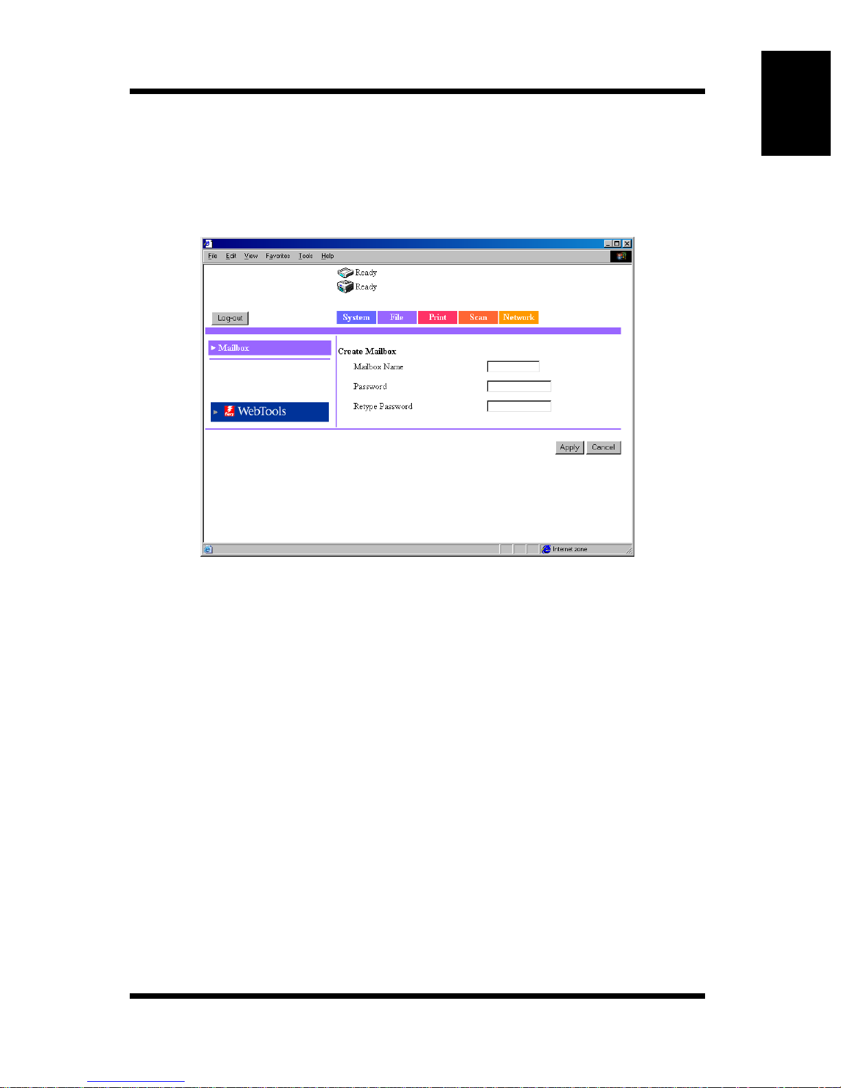
Creating a Mailbox
Click the [Create] button on the mailbox list screen to show a screen used to
create a mailbox.
Up to 20 mailboxes can be created.
Using Printer Management Utility Chapter 1
Mailbox Name: Enter the mailbox name.
(Enter up to 12 characters.)
Password: Enter the password. You can also select not to use a
password.
(Enter up to 40 characters.)
Retype Password:
Reenter the string that you entered in the “Password”
box.
[Apply] button: Click the button to apply the new settings.
[Cancel] button:Click the button to clear the settings that were entered
or selected.
1-39
Page 45
Using Printer Management Utility Chapter 1
1.5 Administration Mode
Deleting a Mailbox
To delete a mailbox, select the mailbox you wish to delete from the mailbox
list and open the file list in the mailbox. (Enter the password as necessary.)
Click the [Delete Mailbox] button at the lower right corner of the file list
screen to delete the mailbox and return to the mailbox list screen.
Note
• When de leti ng a m ail box, also delete the on e-to uch k e y re gis tr ati on wi th
the destination set to that mailbox. (The one-touch key registration is not
automatically deleted.) (See p. 1-27.)
1-40
Page 46
1.5 Administration Mode
1.5.3 Print Tab
The [Print] tab is used to configure the printer controller.
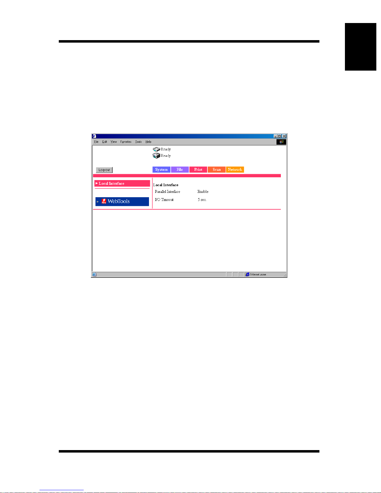
Local Interfac e
This screen appears when you click the [Local Interface] menu on the [Print]
tab. The screen is used to show or set information concerning the local port.
Using Printer Management Utility Chapter 1
P arallel Interface:
Bidirectional communications setting
I/O Timeout: Enter the wait time (second(s)) that is used to determine
the completion of the job after the data received
through the parallel port stops.
1-41
Page 47
Using Printer Management Utility Chapter 1
1.5 Administration Mode
1.5.4 Scan Tab
The [Scan] tab is used to enter and confirm settings concerning mail
transmission and delete all one-touch keys.
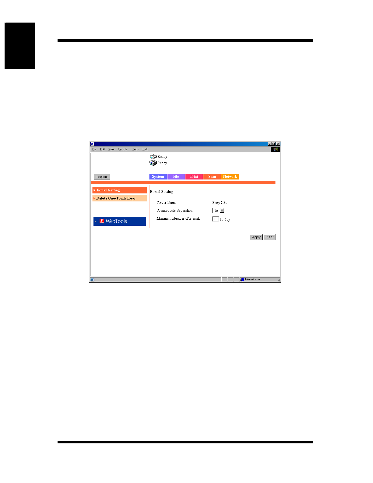
Scan Setting
This screen appears when you click the [Scan Setting] menu on the [Scan] tab.
The screen is used to enter and confirm settings concerning mail transmission.
Server Name: Device name
The “server name” is added to the front of the name of
the image file created by the scan function.
(See p. 2-44.)
Scanned File Separation:
Sets whether to divide the scan data by pages when the
data exceeds the maximum size.
Settings No or Yes
Maximum Number of E-mails:
Specify the maximum number of separations that is
allowed when the scan data is segmented for transmission.
(See p. 2-17.)
Settings 1 to 10
1-42
Page 48
1.5 Administration Mode
[Apply] button: Click the button to apply the new settings.
[Clear] button: Click the button to clear the settings that were entered
or selected.
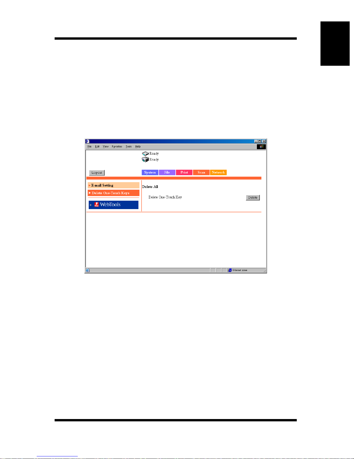
Delete One-Touch Keys
This screen appears when you click the [Delete One-Touch Ke ys] menu on the
[Scan] tab. The screen is used to delete settings registered to the one-touch
keys.
Using Printer Management Utility Chapter 1
Delete One-Touch Key/[Delete] button:
Click the button to delete all settings registered to the
one-touch keys.
1-43
Page 49
Using Printer Management Utility Chapter 1
1.5 Administration Mode
1.5.5 Netwo rk Tab
The [Network] tab shows settings concerning the Fiery X3e 31C-M network.
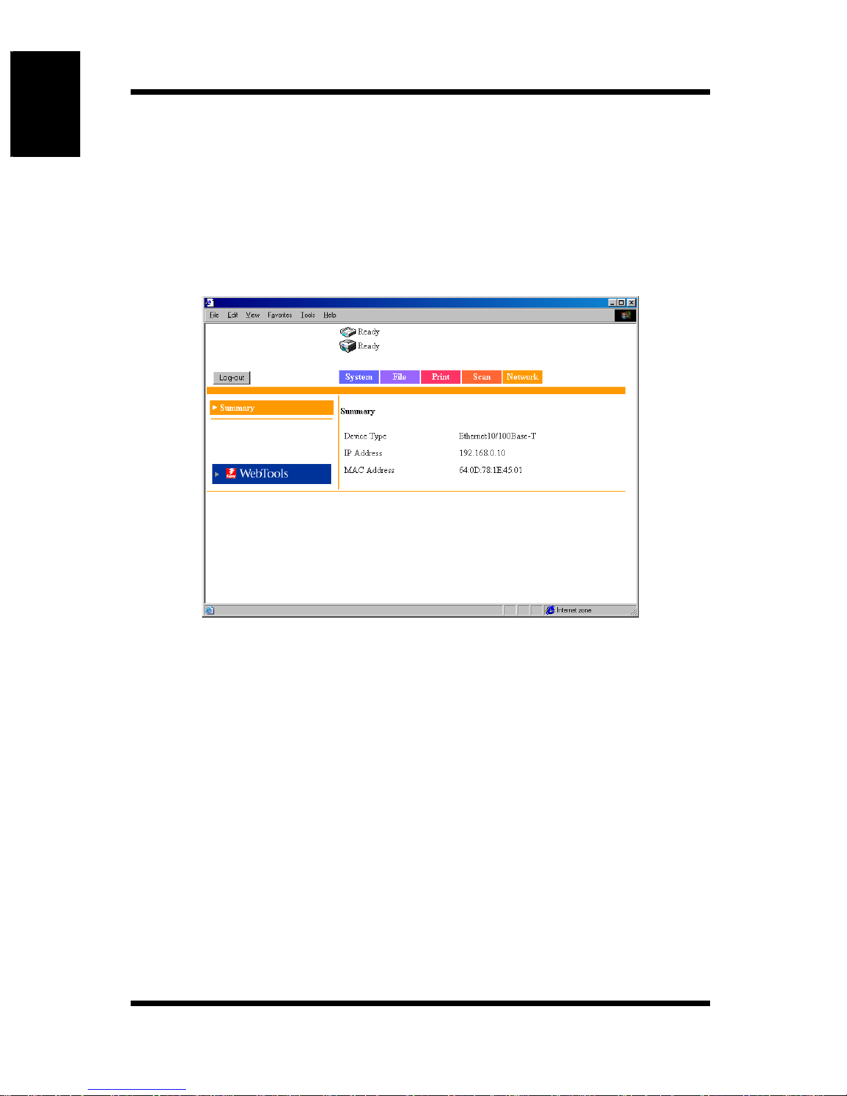
Summary
This screen appears when you click the [Summary] menu on the [Network]
tab. It shows a summary of the printer controller interface (TCP/IP settings).
Device Type: Interface type
IP Address: IP address of the printer controller
MAC Address: MAC address of the printer controller
1-44
Page 50

Chapter 2
Using the Scanner Mode
Using the Scanner Mode Chapter 2
Page 51
2.1 Overview
2.1 Overview
The following type s of scanner mod es are a v a ilable on the Digital Copier. Use
the appropriate type that matches your network environment and application.
• Scan to E-mail:
Using the Scanner Mode Chapter 2
Sends scanned data as an attachment to an e-mail (
• Scan to FTP Server:
Sends scanned data to an FTP server (
• Scan to Mailbox:
Sends scanned data to the controller HDD (
• Internet FAX:
Attaches the scanned data to an e-mail and sends it to a device that
supports Intern e t FAX (
* Scanned data: Image data scanne d usin g the Digita l Cop ie r.
☞p. 2-6)
☞p. 2-4)
☞p. 2-5)
☞p. 2-3)
Note
• This manual does not cover the operating procedures of Fiery Remote
Scan 5. For details, see the manual that came with the controller.
2-2
Page 52
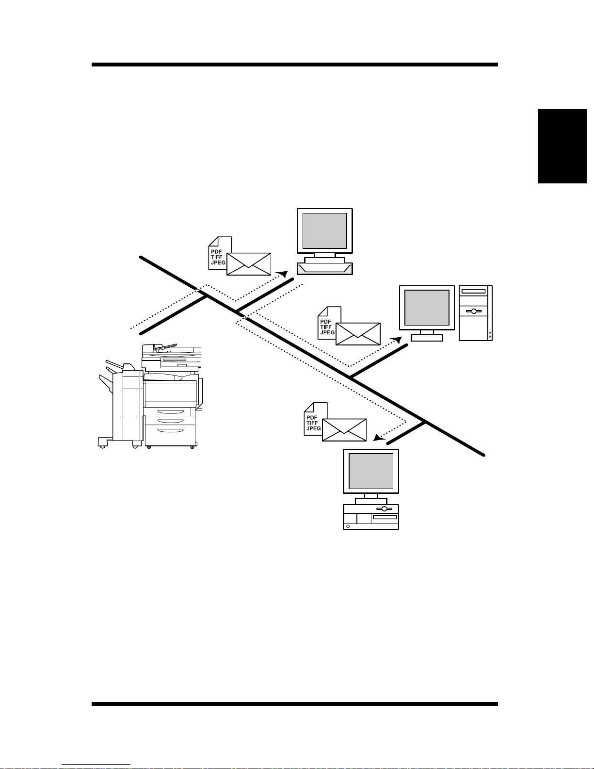
2.1.1 Scan to E-mail
• Sends the scanned image data as an attachment file to an e-mail.
• Suitable for sending low-resolution data.
• Requires a network environment with a mail server.
Mail server
2.1 Overview
Client PC
Client PC
Using the Scanner Mode Chapter 2
2-3
Page 53
2.1 Overview
2.1.2 Scan to FTP Server
• Sends the scanned image data to a specified folder on the FTP server.
• Suit able for sending high- resolution data.
• Requires a network environment with an FTP server.
• Allows you to select whether to send information indicating the storage
location of the image data by e-mail using the e-mail notification
function (see p. 2-16). (A mail server is required for using the e-mail
notificati on func tion.)
• Possible to access FTP servers on the Internet via a proxy server. (A
proxy server is required.)
FTP server
Using the Scanner Mode Chapter 2
Client PC
Mail server
2-4
Page 54
2.1 Overview
2.1.3 Scan to Mailbox
• Sends the scanned image data to a specified folder (Mailbox) on the
controller HDD.
• Suit able for sending high- resolution data.
• Allows you to select whether to send information indicating the storage
location of the image data by e-mail using the e-mail notification
function (see p. 2-16). (A mail server is required for using the e-mail
notificati on func tion.)
Mailbox
Controller
HDD
Computer
Using the Scanner Mode Chapter 2
Mail server
2-5
Page 55
2.1 Overview
2.1.4 Internet FAX
Transmission
• Attaches the scanned image data to an e-mail and sends it to a device
that supports Internet FAX.
• The image data is sent in the following format: TIFF, 200 × 200 dpi,
monochrome, A4/Letter size, with MH compression.
Note
• When sending document data using Internet FAX, you must check
whether the receiving side is capable of receiving Internet FAX in
advance.
• If a document larger than A4/Letter size is scanned, the doc ument is
automatically compressed and transmitted as A4/Letter size.
Using the Scanner Mode Chapter 2
Mail server
TIFF file
Monochrome
200 × 20 0 dpi
MH compression
Devi ce tha t supports
Internet FAX
Printout
2-6
Page 56
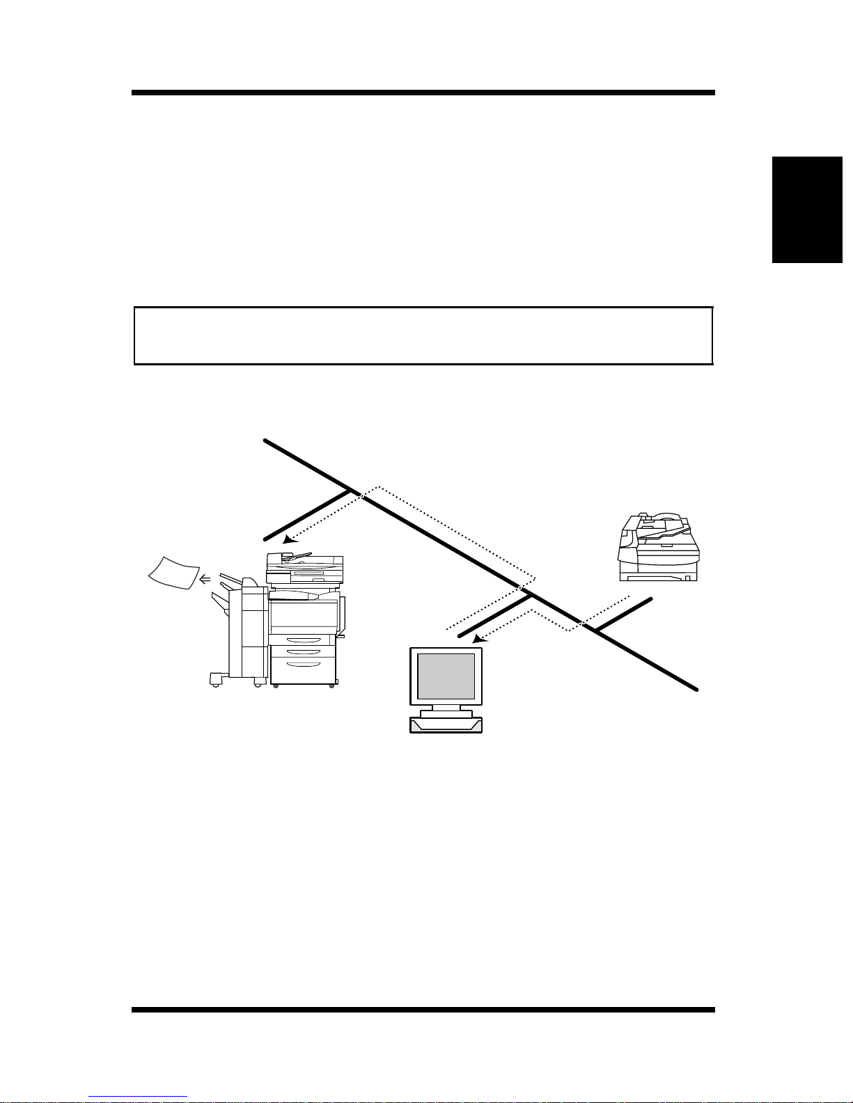
2.1 Overview
Reception
• Receives e-mails sent from a device that supports Internet FAX and
prints out the data.
• The following image data can be received.
TIFF format, 200 × 200 dpi/200 × 100 dpi, monochrome, A4/Letter
size, and MH/MR/MMR compression.
Note
• If a document larger than A4/Letter size is received, the document is
automatically compressed and printed as A4/Lett er size.
Device that
supports
Internet FAX
Using the Scanner Mode Chapter 2
Printout
Mail server
2-7
Page 57
2.1 Overview
2.1.5 Environment Required for Sending
Image Data
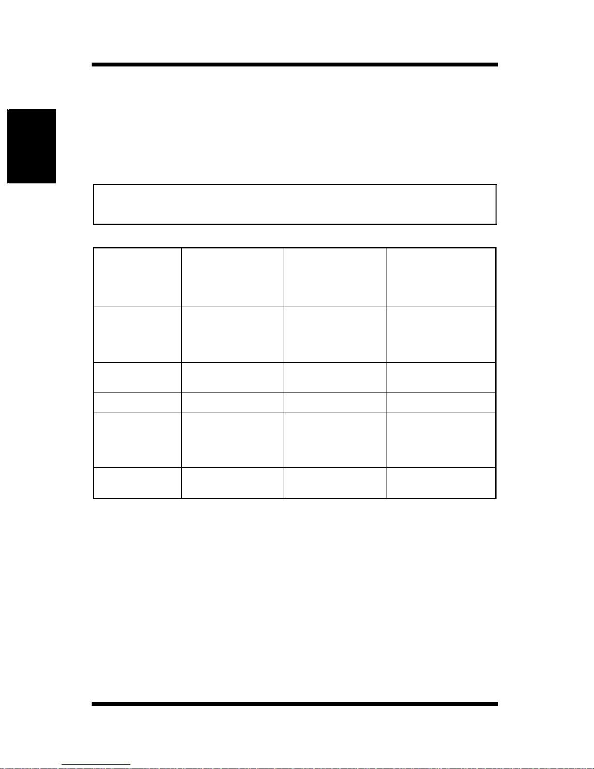
The following environment is required to send image data (send and receive
for Internet FAX) using the scan function.
Note
• All scan functions can only be used under a TCP/IP network
environment.
Using the Scanner Mode Chapter 2
Environment
Required to
Transfer Image
Data
Mail server Mail client
E-mail
FTP
Mailbox
Internet FAX
transmission
Internet FAX
reception
*1: Since the image data is transferred directly to the mailbox in the controller
HDD, servers such as the mail server are not neede d.
FTP server FTP client
None*
Mail server — An upper limit file
1
— Mail server
Environment
Required to
Receive Image
Data
computer
computer
Web browser
Other Limitatio ns
An upper limit file
size may be
specified on the
mail server.
size may be
specified on the
mail server.
2-8
Page 58

2.2 Controller Setup Items
2.2 Controller Setup Items
The following settings must be made on the controller side to use the scan
function.
2.2.1 Network Protoco l Settings
Network communications using the TCP/IP protocol must be possible. Use
the [Setup Mode] on the controller operation panel to enter the settings. For
details on the setup items and procedure, see the Controller User Manual.
2.2.2 Scan Settings
Use the “Administration Mode” of Printer Management Utility and the [Setup
Mode] on the controller operation panel to enter the settings. For details on
Printer Management Utility, see chapter 1, “Using Printer Management
Utility”.
Printer Management
Utility
Administration Mode: [Scan] tab
Server Name
Scanned File Separation
Maximum Number of
E-mails
{
: required, —: Not required
*: Check the settings.
Scan to
E-mail
{
*
{
{
Scan to
FTP
{
*
———
———
Scan to
Mailbox
{
*
Internet
FAX
{
Using the Scanner Mode Chapter 2
*
2-9
Page 59
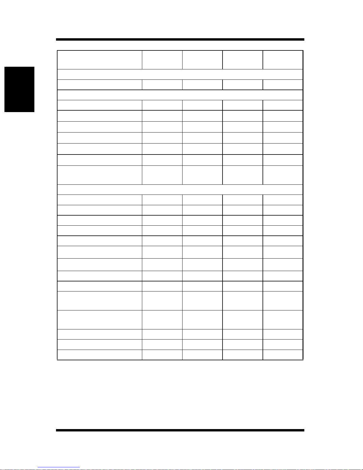
2.2 Controller Setup Items
Using the Scanner Mode Chapter 2
Controller
Operation Panel
Setup Mode: [Service Setup]
Enable Mailbox Password — —
Setup Mode: [Network Setup] — [Service Setup] — [FTP Setup]
Enable FTP Services —
Enable Proxy Setup
Proxy Server IP Address
Proxy Server Port Number
Proxy Server Timeout
Proxy Server User Name
Proxy Server User
Password
Setup Mode: [Network Setup] — [Service Setup] — [E-Mail Setup]
Enable E-mail Services
Enable Print Via E-mail — — —
Outgoi ng Server
Scan to
E-mail
—
—
—
—
—
—
{
{
Scan to
FTP
{
z
z
z
z
z
z
——
——
Scan to
Mailbox
{
——
——
——
——
——
——
——
Internet
FAX
—
{
{
{
Incoming Server — — —
Server Type — — —
Fiery Email User Name
Fiery Email Domain Name
Account Name — — —
Password — — —
Administrator Emai l User
Name
Administrator Email
Domain Name
Timeout (Sec)
Polling Interval — — —
Maximum Scan File Size
{: required, z: Required depending on the environment, —: Not required
*1: The sender (From) address is Fiery Email User Name@Fiery Email Domain
Name. (See p. 2-18. )
*2: Administrator Email User Name@Administrator Email Domain Name is the error
notification destination if the mail does not reach the recipient for some reason.
(See p. 2-18.) Howev er, if the mail is not transmitted, the error is not notified.
z
z
z
z
{
{
1
*
1
*
2
*
2
*
——
——
——
——
——
———
z
z
z
z
{
{
{
{
{
{
1
*
1
*
2
*
2
*
2-10
Page 60
2.3 Setup Items for Scanning
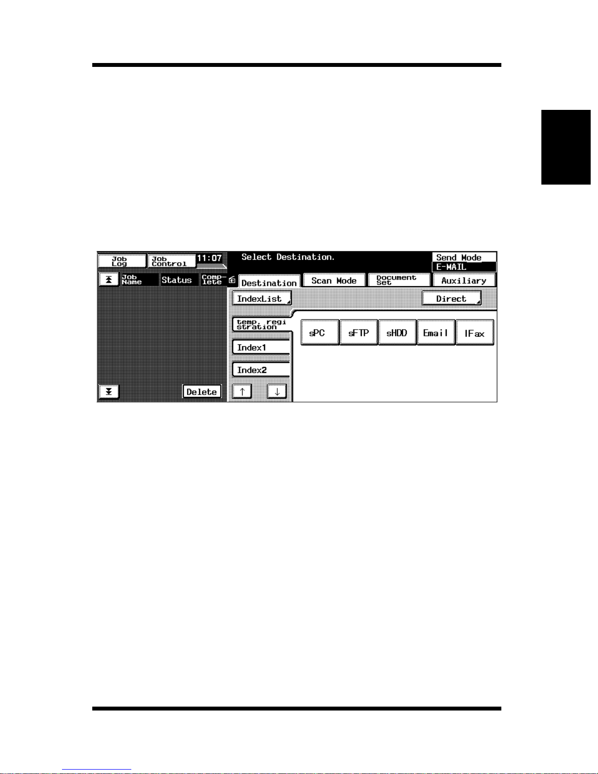
2.3 Setup Items for Scanning
When transferring image data using the scan f unction, th e follo wing items can
be entered on the copier operation panel.
2.3.1 Entering the Setup Screen
1. Press the [Scan] key.
2. Touch t he d esi red ta b fro m [Des ti nati on] , [S can Mo de], [ D ocumen t Set ] ,
and [Auxiliary].
Using the Scanner Mode Chapter 2
2-11
Page 61
2.3 Setup Items for Scanning
2.3.2 Destination Tab
You can specify the transmission destination of the image data.
[Temp. Registration]:
Key registered usin g [Temp Registrati on] on Printer
Management Utility. After the scanning is complete,
the key is automatically cleared.
[Index]: Touch Index to show the key registered using [One
Touch Key Registration] on Printer Management
Utility.
[Direct]: When transferring image data using e-mail or Internet
FAX, you can send the data by directly entering the
mail address. (One address only)
Note
Using the Scanner Mode Chapter 2
• Multiple tran smission destinations can be specified for mail
transmission and Internet FAX. You can specify up to 50 addresses
using up to 1800 characters.
In addition, addresses can be specified using the one-touch key and
address entry (one address entry only) simultaneously.
[Auxiliary]: When transferring image files using “Scan to FTP
Server” or “Scan to Mailbox”, you can select the e-mail
notification destination (see p. 2-16) from the registered
one-touch keys.
Note
• The [Notification Address] that is selected under the [Auxiliary] tab
has priority over [Notification Address] that is registered to the one touch key.
2-12
Page 62
2.3 Setup Items for Scanning
2.3.3 Scan Mode Tab
You can specify the transmission method of the document.
[Color/File]: Specifies the color mode, da ta format, and compression
method.
Setting s
Color mode : Full Color, Grayscale, or Monochrome
File Format : PDF, TIFF, or JPEG
Note
• If the transmission destination is set to a mailbox, the file format is
specified when the data is downloaded from the mailbox to the
computer. You do not have to set the format using [File Format] on
this screen.
Compression : High Quality, Standard, or High Compression
Note
• If [Color Mode] is set to [Monochrome], [Compression] does not
appear.
[Resolution]: Specifies the resolution.
Settings 200 dpi, 300 dpi, 400 dpi, 600 dpi
[Background Remove]:
Enter settings concerning background remove and
document brightness.
Background Remove Enter settings concerning background remove.
Settings
Auto or manual (-5 (maximum removal) to
+2 (minimum removal): 8 levels)
Brightness Specify the brightness of the document.
Settings
-3 (brightest) to +3 (darkest): 7 levels
Using the Scanner Mode Chapter 2
2-13
Page 63
2.3 Setup Items for Scanning
[Scan Size]: Specify the scan size of the document.
You can also specify an arbitrary size (in unit of
millimeter or 1/16 inch).
In addition, you can also specify the erase position and
erase width.
2.3.4 Document Set Tab
You can specify the document type.
[Doc. Mode]: Specify the document scan mode.
Settings 1 or 2
[Margin]: Specify the direction of the margin of the document for
duplex printing.
Settings left binding or top binding
Using the Scanner Mode Chapter 2
[Original Direction]:
Specify the image direction with the document set in
the tray.
Settings Not selected (auto detection),
Portrait document Wide/Tall,
Landscape Wide/Tall,
Note
• If an image data that results from scanning a document larger than
A4/Letter size is displayed on the computer, it is displayed as a
portrait image.
[Mixed Orig. Detection]:
To scan documents of different sizes, select the [Mixed
Orig. Detection] key.
[Separate Scan]:
If “Separate Scan” is selected, the following data is
handled as a single job: the data that is scanned until the
[Finish] key that appears on the control operation panel
after the scan operation complete is selected.
2-14
Page 64
2.3 Setup Items for Scanning
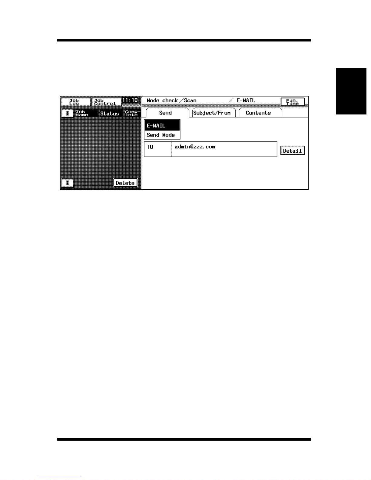
2.3.5 Checking the Settings on the
Destination Device
Press the [Mode Check] button to view the settings on the destination device.
2.3.6 Registering the Scan Mode Default
Settings
You can arbitrary specify the default settings of the Scan Mode.
1. Press the [Scan] key on the copier operation panel to enter the Scan
Mode.
2. Select the setting to make the default value in the Scan Mode.
3. Press the [Utility] key.
4. Touch the [Input] key.
5. Touch the [Reset Mode] key.
6. Touch [Scan] followed by [Set-up Mode].
7. Touch [OK].
You can set the default settings of the Scan Mode to factory default by
touching [Factory Def aul t].
Using the Scanner Mode Chapter 2
2-15
Page 65
Using the Scanner Mode Chapter 2
2.4 E-Mail Notification
2.4 E-Mail Notification
The e-mail notification function is used to notify using an e-mail the
information indicating the storage location of the image data that th e scan
function created. The image data is not attached to the mail. The side
receiving the mail can refer to the information written in the mail text to
access the storage location of the image data.
When transmitting image data by selecting a one-touch key (see p. 2-31) that
has server transmission or mailbox registered and a Notification Addres s is set
to the selected one-touch key, an e-mail notification is transmitted. You can
also specify Notification Address on the operation panel of the copier. (See p.
2-12.)
Note
• Mails that are transmitted by the e-mail not i fication function are
transmitted according to the mail transmission settings. You must set the
mail transmission settings to use the e-mail notification function.
2.4.1 N ot ifie d Information
The following information is notified by mail.
For server transmission
• IP address of the FTP server
• Directory in which the image data is saved
• File name of the image data
Note
• You may need to enter a user name and a password to acce ss the FTP
server.
• The user name and password are not notified by mail.
2-16
Page 66
2.5 URL Notification
For mailbox transmission
• http://IP address of the controller
• Mailbox name
• File name of the image data
Note
• You may need to enter a password to access the mailbox.
• The password is not notified by mail.
2.5 URL Notification
The URL notification function is used to notify using an e-mail the URL
indicating the storage location of the image data that the scan function created.
The image data is not attached to the URL notification mail. The side
receiving the URL notif ication m ail can double-click the URL written in the email text to access the storage location of the image data.
A URL notificati on mail is tr ansmitte d in the follow ing case s.
When the size of the mail e xceeds the upper limit specif ied by Max imum Scan
File Size (see p. 2-21) on the Scan to E-mail function
In this case, the image data is saved to the controller HDD, and a URL
indicating the storage location is transmitted by mail.
Note
• URL notification mails are transmitted according to the mail transmission
settings. You must set the mail transmission settings to use the URL
notificati on function.
• If Scanned File Separation (see p. 2-22) is set to Yes and the upper mail
limit specified by Maximum Scan File Size is exceeded, the image data
is first segmented into pages and transmitted. Therefore, the URL
notification mail is not transmitted.
Howev er, if the upper mail limit specified by Maximum Scan File Size is
exceeded even after separating the data up to the number specified by
Maximum Number of E-mails, the image data is saved to the controller
HDD, and a URL notification mail is transmitted. (The image data is
stored to the HDD without separation.)
Using the Scanner Mode Chapter 2
2-17
Page 67

2.6 Entering the Controller Setup Screen
2.6 Entering the Controller Setup Screen
You can enter the controller settings from Printer Management Utility (see
chapter 1, “Using Printer Management Utility”) or the controller operation panel
that is displayed on the copier operation panel. To configure the controller from
the controller operation panel, you must displ ay t he setup screen.
Displaying the Setup Screen
1. On the copier operation panel, to uch [U tility] — [Co ntro ller Deta ils].
2. On the controller operation panel, touch [MENU].
3. Use the up and down keys to show [Run Setup].
4. Touch the key to the right of [Run Setup] to show [Continue to Setup?].
5. Touch the key to the right of [OK] to show the setup screen.
Using the Scanner Mode Chapter 2
2.7 Setting the Error Notification
Destination
You can carry out the following steps to specify the des tination to notify errors
when mails transmitted using the Scan to E-mail, Internet FAX transmission,
e-mail notification function, or URL notification function do not reach the
destination address. However, if the mail is not transmitted, the error is not
notified.
1. Show the setup screen from the controller operation panel.
2. Select [Network Setup] — [Service Setup] — E-Mail Setup and enter the
following settings.
[Administrator Email User Name]:
Specify the E-mail user name of the controller
administrator.
[Administrator Email Domain Name]:
Specify the mail server domain name to which the
administrator belongs.
Note
• Administrator Email User Name@Administrator Email Domain Name is
the error notification destination.
2-18
Page 68
2.8 Setting the Sender (From) Address
2.8 Setting the Sender (From) Address
You can carry out the following steps to specify the mail address that appears
in the sender (From) line of the mail transmitted by Scan to E-mail, Internet
FAX transmission, e-mail notification function, and URL notification
function.
1. Show the setup screen from the controller operation panel.
2. Select [Network Setup] — [Service Setup] — [E-Mail Setup] and enter
the following settings.
[Fiery Email User Name]:
Specify the mail user name of the sender.
[Fiery Email Domain Name]:
Specify the mail server domain name to which the
sender belongs.
Note
• The sender (From) address is Fiery Email User Name@Fiery Email
Domain Name.
Using the Scanner Mode Chapter 2
2-19
Page 69
2.9 Scan to E-Mail Function
2.9 Scan to E-Mail Function
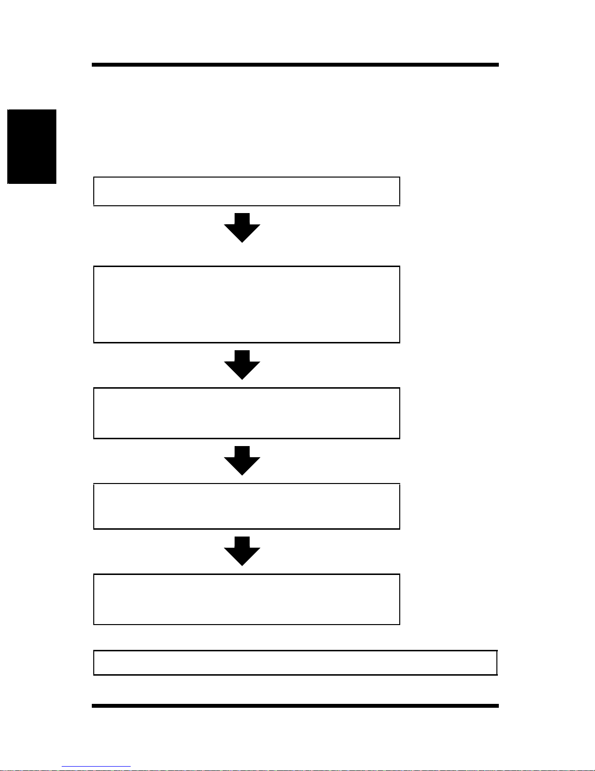
Below is the setup and operation flow of the mail function.
Location of
operation
Using the Scanner Mode Chapter 2
A Set the controller
B Register the one-touch key or
temporary registration key
(You can also enter the address directly from the
copier operation panel. See p. 2-12)
C E nter scan settings
Controller
operation panel
Printer
Management
Utility
(See p. 2-21.)
Printer
Management
Utility
(See p. 2-31.)
Copier
operation panel
(See p. 2-11.)
D Set the document and transfer the
image data to the mail server
ERetrieve mail
Note
• Image data is transmitted using port number “25”.
2-20
Copier
operation panel
Mail client
computer
(See p. 2-22.)
Page 70
2.9 Scan to E-Mail Function
2.9.1 Setting the Controller
To perform mail transmission, enter the settings for accessing the mail server
(SMTP server).
1. Show the setup screen from the controller operation panel.
2. Select [Network Setup] — [Service Setup] — [E-Mail Setup] and enter
the following settings.
[Enable E-mail Services]:
Select “Yes”.
[Outgoing Server]:
Enter the IP address of the mail server (SMTP).
[Time Out (sec)]:
Set the timeout value for accessing the mail server.
Unless there is a specific reason to do so, use the
default valu e.
(common setting for the SMTP server and POP3
server)
[Maximum Scan File Size]:
Set the maximum transmission mail size.
3. Start Printer Management Utility.
4. Enter the password and log into the Administrator Mode.
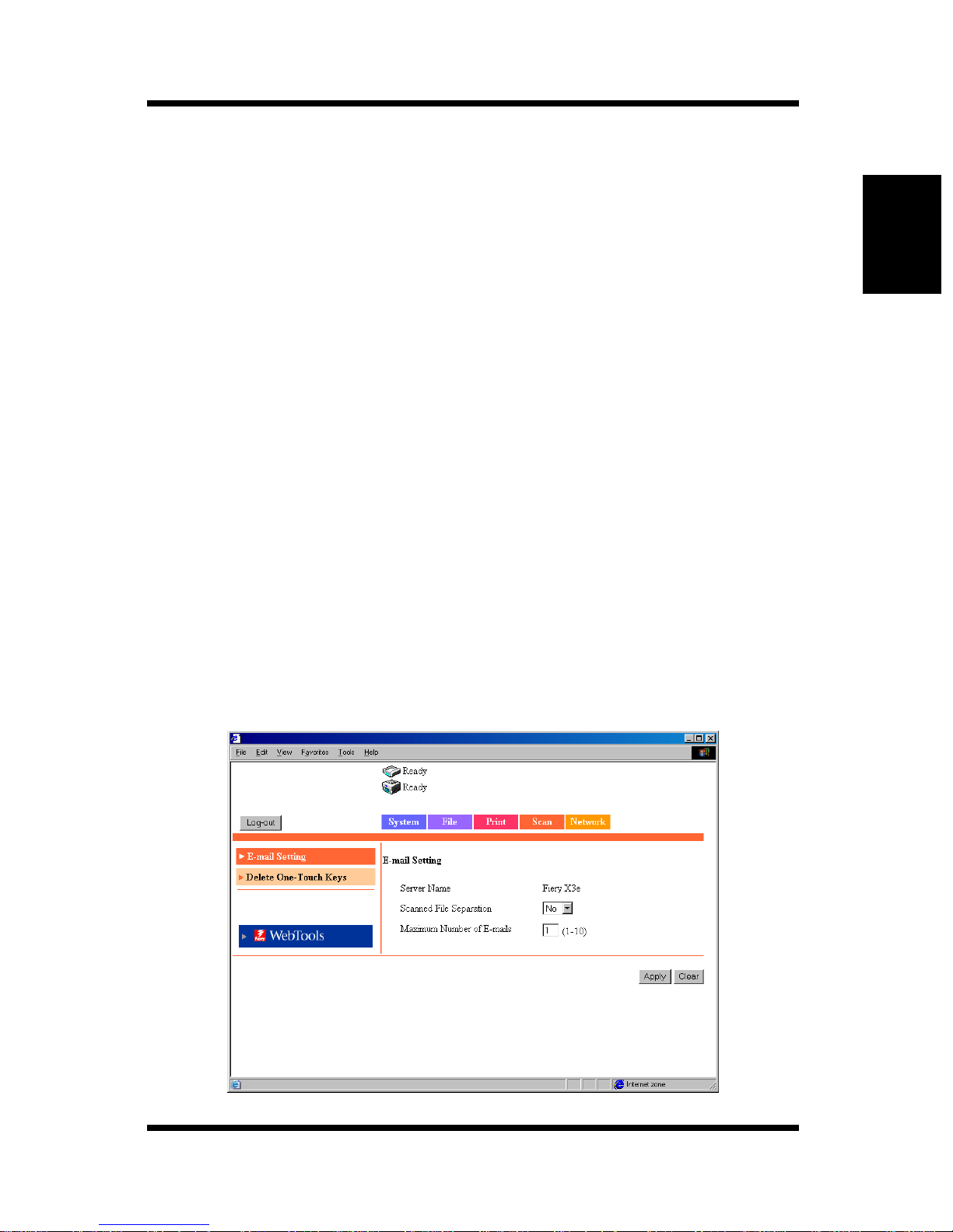
5. Select [Scan Setting] from the [Scan] tab.
Using the Scanner Mode Chapter 2
2-21
Page 71

Using the Scanner Mode Chapter 2
2.9 Scan to E-Mail Function
Server Name: The “server name” is added to the beginning of the
name of the image file created by the scan function.
(see p. 2-44)
Scanned File Separation:
If set to “Yes”, the image data is segmented into pages
and transmitted when the upper limit specified by
Maximum Scan File Size is exceeded.
For the correlation between Maximum Scan File Size (see p. 2-21),
Scanned file Separat i on, and URL noti fication function, see “U RL
Notification” on page 2-17.
Maximum Number of E-mails:
Specify the number of separations that is allowed when
the mail is segmented for transmission.
For the correlation between Maximum Scan File Size (see p. 2-21),
Scanned File Separ ation, URL no tifi cation fu nction, and Maximum
Number of E-mails, see “URL Notifi cati on” on page 2-17.
2.9.2 Retrieving Mails
To retrieve mails transferred to the mail server, you must access and retrieve
the mail using the mail client computer.
For details on the operation of your mail client software, see the manual or
help provided with the software program.
2-22
Page 72
2.10 Scan to Mailbox Function
2.10Scan to Mailbox Function
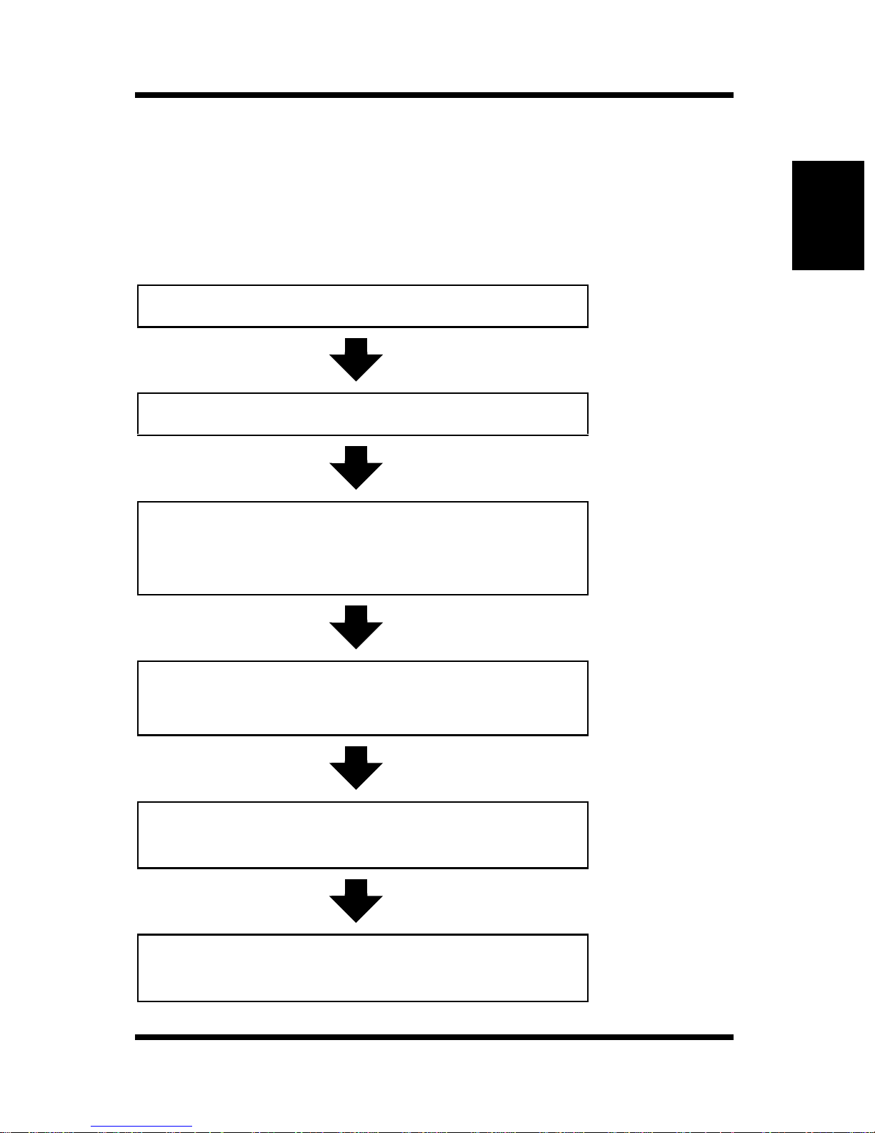
Below is the setup and operation flow of the Scan to Mailbox function.
(For details on the hold period of the image data in the mailbox, see p. 2-46.)
Location of
operation
A Set the controller
B Creat e a mail box
C Register the one-touch key or
temporary registration key
D E nter scan settings
Controller
Operation
Panel
(See p. 2-24.)
Printer
Management
Utility
(See p. 2-24.)
Using the Scanner Mode Chapter 2
Printer
Management
Utility
(See p. 2-31.)
Copier
operation panel
(See p. 2-11.)
E Set the document and transfer the im age
data to the mailbox in the controller HDD.
F Down load the image data to the
computer
Copier
operation panel
WebTools
(See p. 2-25)
2-23
Page 73
2.10 Scan to Mailbox Function
Note
• If you use Fiery Remote Scan 5, you can download the image data in
the mailbox to the compu ter or transfer the data via FTP, E-mail, and
other means. For details, see the Controller User Manual.
2.10.1 Setting the Controller
Enter the setting for allowing passwords to be assigned to mailboxes.
1. Show the setup screen from the controller operation panel.
2. Select [Server Setup] and enter the following settings.
[Enable Mailbox Password]:
Select “Yes” to allow passwords to be assigned.
2.10.2 Creating a Mailbox
Using the Scanner Mode Chapter 2
Create a mailbox, a storage location of the image data.
Note
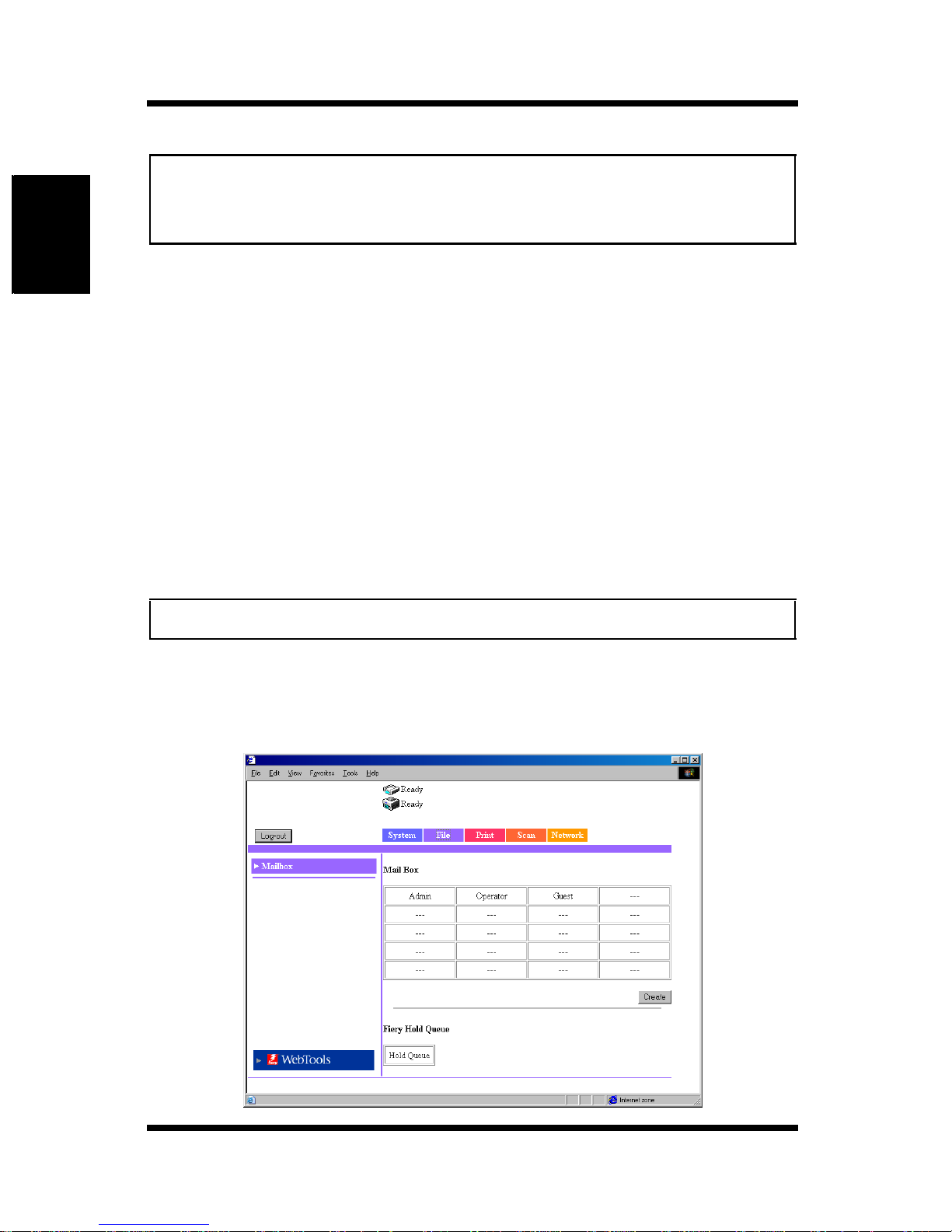
• “Admin”, “Operator”, and “Guest” are registered by default.
1. Start Printer Management Utility.
2. Enter the password and log into the Administrator Mode.
3. Select [Mailbox] from the [File] tab.
2-24
Page 74
2.10 Scan to Mailbox Function
4. Click [Create] to open the Create Mailbox screen.
Enter setti ng s f or “Mailbox Nam e”, “Passw o r d ”, and “R et y pe Passwor d ”
and click [Apply].
Note
• Up to 20 mailboxes can be created (including “Admin”, “Operator”, and
“Guest”).
2.10.3 Downloading the Image Data to the
Computer
Download the image data from the mailbox in the controller HDD to your
computer. Download the image data using WebTools.
1. Start Printer Management Utility.
2. Click [WebTool s].
3. Click [WebScan].
Using the Scanner Mode Chapter 2
4. Enter the mailbox name in [Mailbox] and click [Refresh].
5. Enter the password in the password input dialog box.
A list of stored image data is displayed.
6. Click the file to be downloaded.
7. Select [File Format].
8. Click [Save As] to download the file.
Note
• If the e-mail notification address is specified, the information indicating
the storage location of the image data is notified by mail.
2-25
Page 75
2.11 Scan to FTP Server Function
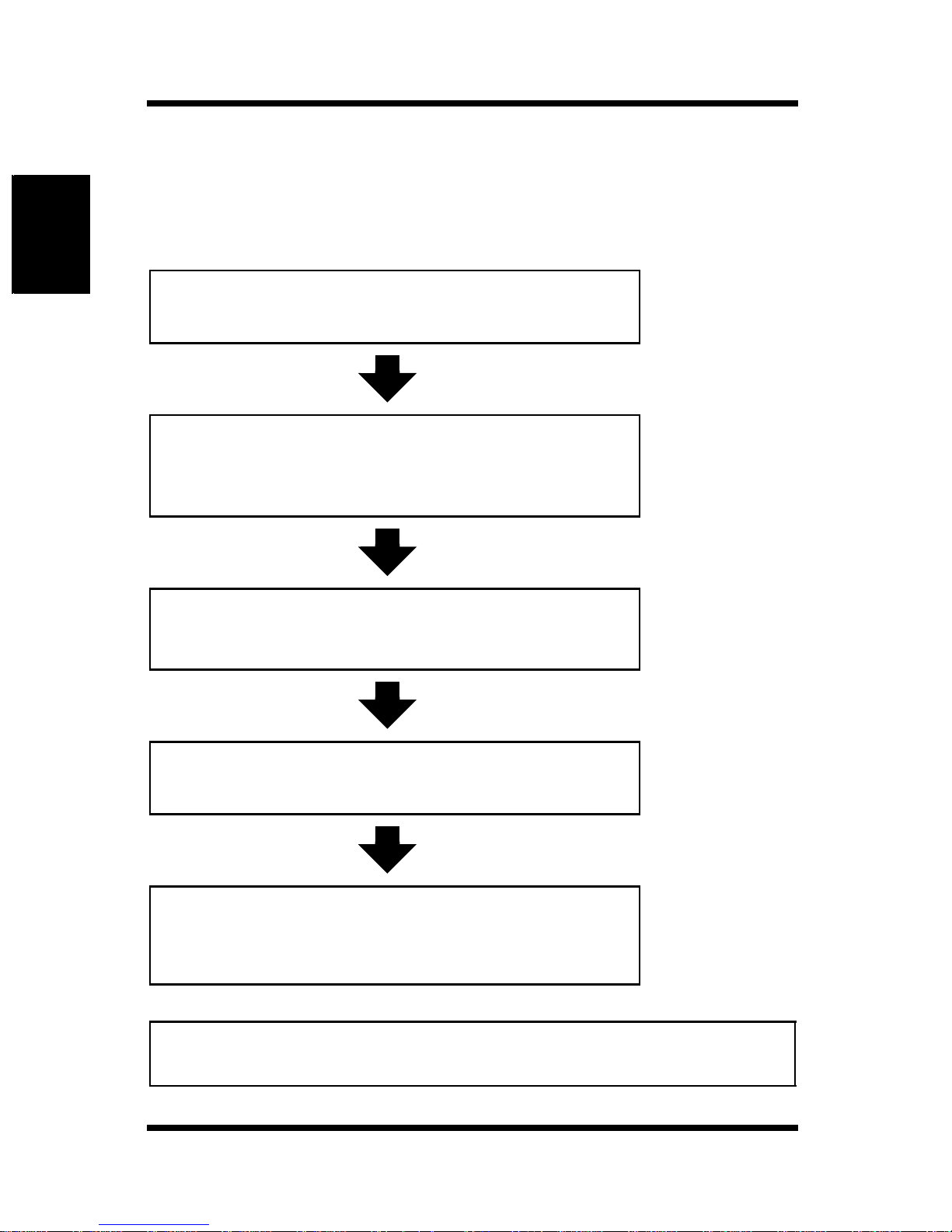
2.11Scan to FTP Server Function
Below is the setup and operation flow of the Scan to FTP Server function.
Location of
operation
Using the Scanner Mode Chapter 2
A Enable the FTP transfer function
(Enter proxy settings as necessary. See p. 2-27.)
B Register the one-touch key or
temporary registration key
C E nter scan settings
Controller
operation panel
(See p. 2-27.)
Printer
Management
Utility
(See p. 2-31.)
Copier
operation panel
(See p. 2-11.)
D Set the document and transfer the
image data to the FTP server
E Retrieve the image data
Copier
operation panel
FTP client
computer or Printer
Management Utility
(See p. 2-28.)
Note
• Image data is transferred using port number “21”. Passive mode is not
suported.
2-26
Page 76

2.11 Scan to FTP Server Function
2.11.1 Enabling the FTP Transfer Function
1. Show the setup screen from the controller operation panel.
2. Select [Network Setup] — [Service Setup] — [FTP Setup] and enter the
following settings.
[Enable FTP Services]:
Select “Yes”.
2.11.2 Proxy Settings
Enter proxy settings as necessary. (Consult your network administrator to see
if proxy settings are required and the setup details.)
1. Show the setup screen from the controller operation panel.
2. Select [Network Setup] — [Service Setup] — [FTP Setup] and enter the
following settings.
[Enable Proxy Setup]:
Select “Yes” to enable the proxy settings.
[Proxy Server IP Address]:
Enter the IP address of the proxy server.
[Proxy Server Port Number]:
Specify the port number of the proxy server.
[Proxy Server Timeout]:
Set the timeout value.
[Proxy Server User Name]:
Enter the user name of the proxy server.
[Proxy Server User Password]:
Enter the password of the proxy server.
Using the Scanner Mode Chapter 2
2-27
Page 77
2.11 Scan to FTP Server Function
2.11.3 Retrieving the Image Data
Retrieve the image data from the FTP server.
The method for retrieving the image data varies depending on the following
cases.
Access the FTP server from your FTP client computer and download the
image data. You may need to enter a user name and a password to access
the FTP server.
Note
• If the e-mail notification address is specified, the information indicating
the storage location of the image data is notified by mail. (S ee p. 2-16.)
Using the Scanner Mode Chapter 2
2-28
Page 78
2.12 Internet FAX Transmission Function
2.12Internet FAX Transmission Function
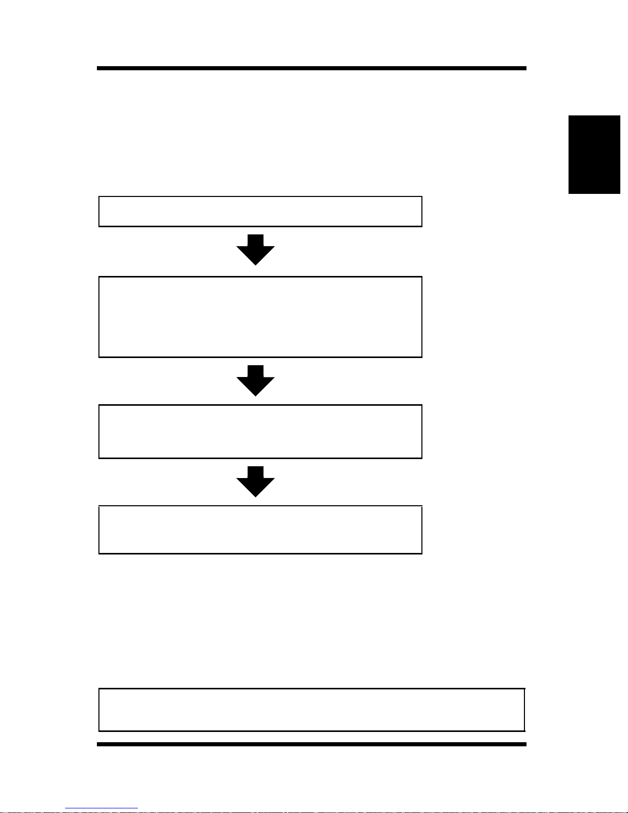
Below is the setup and operation flow of the Internet FAX transmission
function.
Location of
operation
A Set the controller
B Register the one-touch key or
temporary registration key
(You can also enter the address directly from the
copier operation panel. See p. 2-12.)
C E nter scan settings
Controller
operation panel
Printer
Management
Utility
Printer
Management
Utility
(See p. 2-31.)
Using the Scanner Mode Chapter 2
Copier
operation panel
(See p. 2-11.)
D Set the document and transfer the
image data to the mail server
2.12.1 Setting the Controller
Internet FAX Transmission Settings
The image data is transmitted using the same settings as for Scan to E-mail.
For details, see the settings of the “Scan to E-mail” controller (p. 2-21).
Note
• The “Scanned File Separation” and “Maximum Number of E-mails” settings
do not have to be entered, because they are invalid for Internet FAX.
Copier
operation panel
2-29
Page 79

2.13 Internet FAX Reception Function
2.13Internet FAX Reception Function
The settings of the Internet FAX reception function are described below.
2.13.1 Setting the Controller
To receive mails, enter settings for accessing the mail server (POP3/IMAP).
1. Show the setup screen from the controller operation panel.
2. Select [Network Setup] — [Service Setup] — [E-Mail Setup] and enter
the following settings.
[Enable E-mail Services]:
Select “Yes”.
[Enable Print Via E-mail]:
Select “Yes”.
Using the Scanner Mode Chapter 2
[Incoming Server]:
Enter the IP address of the mail server (POP3/IMAP).
[Server Type]: Select the mail server type (POP3/IMAP).
[Account Name]:
Enter the name used to log into the POP3/IMAP server.
[Password]: Enter the password used to log into the POP3/IMAP
server.
[Timeout (sec)]:
Set the timeout value for accessing the mail server.
(common setting for the SMTP server and POP3 server)
[P olling Interval (sec)]:
Set the interval for checking received mails.
Note
• If the e-mail contains a title (subject) and text when receiving Internet
FAX, the title and text are also printed.
2-30
Page 80
2.14 Registering the One-Touch Key and Temporary Registration Key
2.14Registering the One-Touch Key and
Temporary Registration Key
When using the scan function, it is convenient if the transmission destination
is registered to the copier operation panel in advance. The transmission
destination is registered using Printer Management Utility.
2.14.1 One-Touch Key Registration
If the one-touch key is registered in advance, you can immediately recall the
transmission destination. Since you do not have to enter the transmission
destination every time, it is convenient if you register destinations to which
you transmit image data frequently.
Setup procedure
1. Start Printer Management Utility.
2. Select [One Touch Key Registration] from the [Scan] tab.
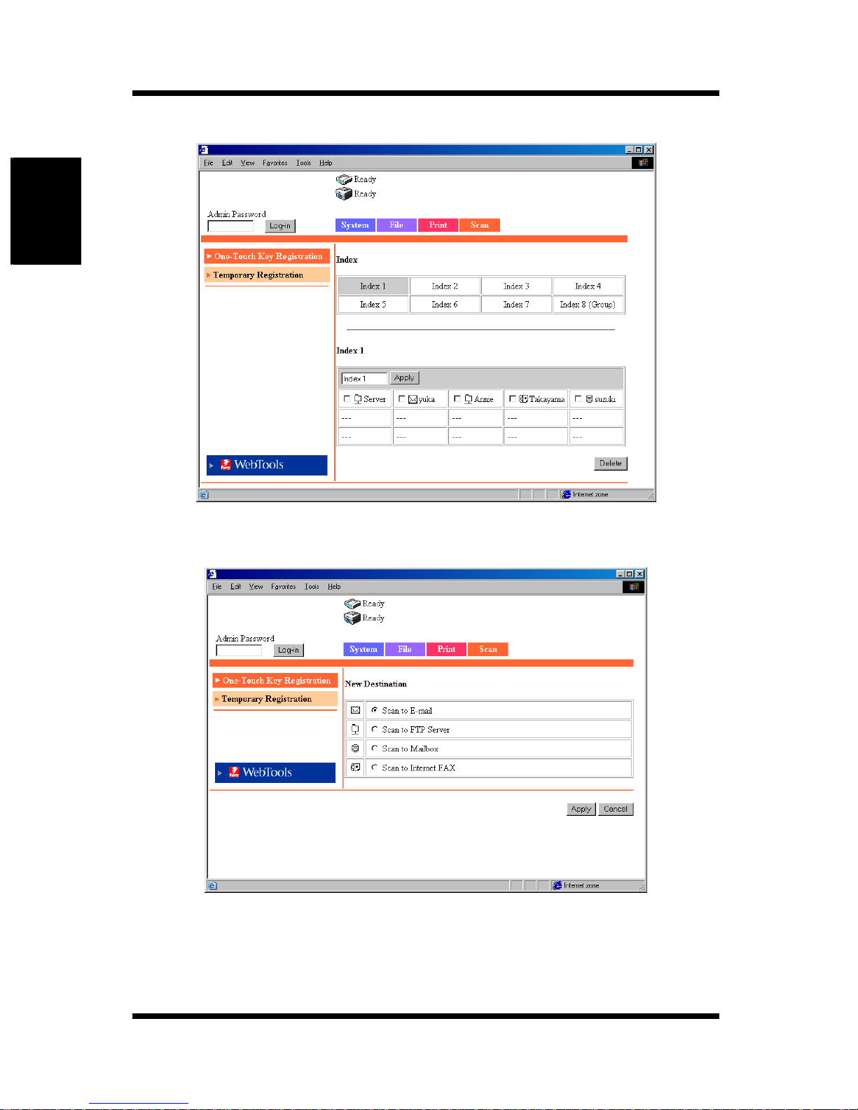
3. A list of one-touch registration appears. Select an index.
[Index 8] is dedicated to group registration. You can register groups for
the mail transmission function and the Inter net FAX transmission
function.
Note
• There are 8 index es total. The default names are [Index 1], [Index 2], and
so on. You can register up to 15 keys in each index from [Index 1] to
[Index 6] and [Index 8 (Group)]. Up to 10 keys can be registered in [Index
7].
Using the Scanner Mode Chapter 2
2-31
Page 81
2.14 Registering the One-Touch Key and Temporary Registration Key
Using the Scanner Mode Chapter 2
4. Click an unregistered box (---).
5. Select the transmission method.
2-32
Page 82
2.14 Registering the One-Touch Key and Temporary Registration Key
Note
• For a group registration, the number of characters for the transmission
destination address is up to 1800 (up to 50 addresses).
• For registration other than groups, the number of characters for the
trans mis s io n destinatio n address is up to 72 .
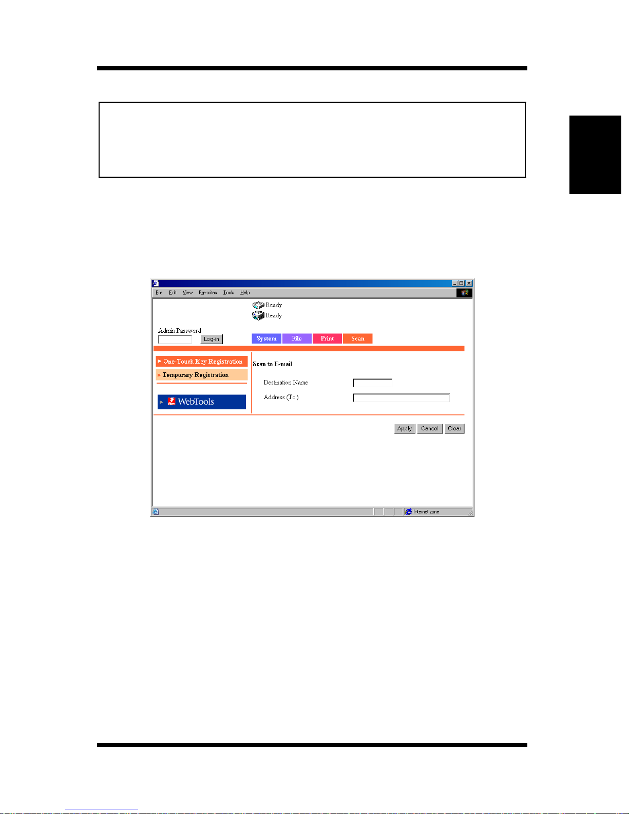
6. Click [Apply].
The setup items corresponding to the transmission method appear.
When Scan to E-mail is selected
Destination Name:
Enter the name of the one-touch key.
Setting Up to 12 characters
Address (To): En ter the transmission destination address.
Setting Up to 72 characters, one address
Using the Scanner Mode Chapter 2
2-33
Page 83
2.14 Registering the One-Touch Key and Temporary Registration Key
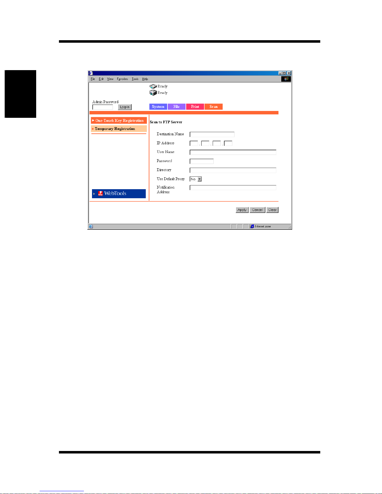
When Scan to FTP Server is selected
Using the Scanner Mode Chapter 2
Destination Name:
Enter the name of the one-touch key.
Setting Up to 12 characters
IP Address: Set the IP address of the FTP server.
User Name: Enter the name used to log into the FTP server.
Password: Enter the password used to log into the FTP server.
Directory: Specify the location (directory) for storing the image
data on the FTP server.
(To speci fy the default folder, leave this blank.)
Use Default Proxy:
Set whether to use the proxy server.
Notification Address (E-Mail Notification Address):
When using the e-mail notification function, enter the
destination mail address. (See p. 2-16.)
Setting Up to 72 characters, one address
2-34
Page 84
2.14 Registering the One-Touch Key and Temporary Registration Key
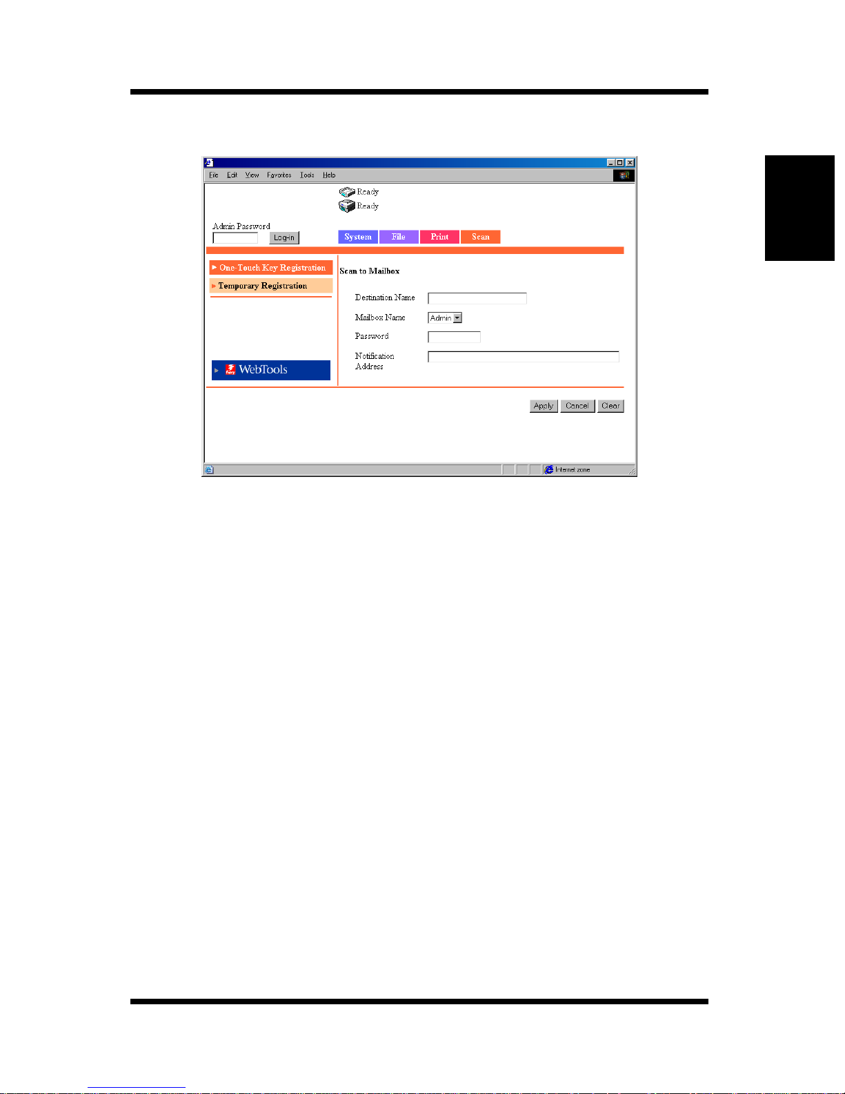
When Scan to Mailbox is selected
Destination Name:
Enter the name of the one-touch key.
Setting Up to 12 characters
Mailbox Name: Select the transmission de stination mailbox.
The list shows the mailboxes that have been registered
using [Mailbox] (p. 2-24).
Password: Enter the password used to access the mailbox.
Setting Up to 8 characters
Notification Address (E-Mail Notification Address):
Enter the e-mail notification destination mail address.
(See p. 2-16.)
Setting Up to 72 characters, one address
Using the Scanner Mode Chapter 2
2-35
Page 85
2.14 Registering the One-Touch Key and Temporary Registration Key
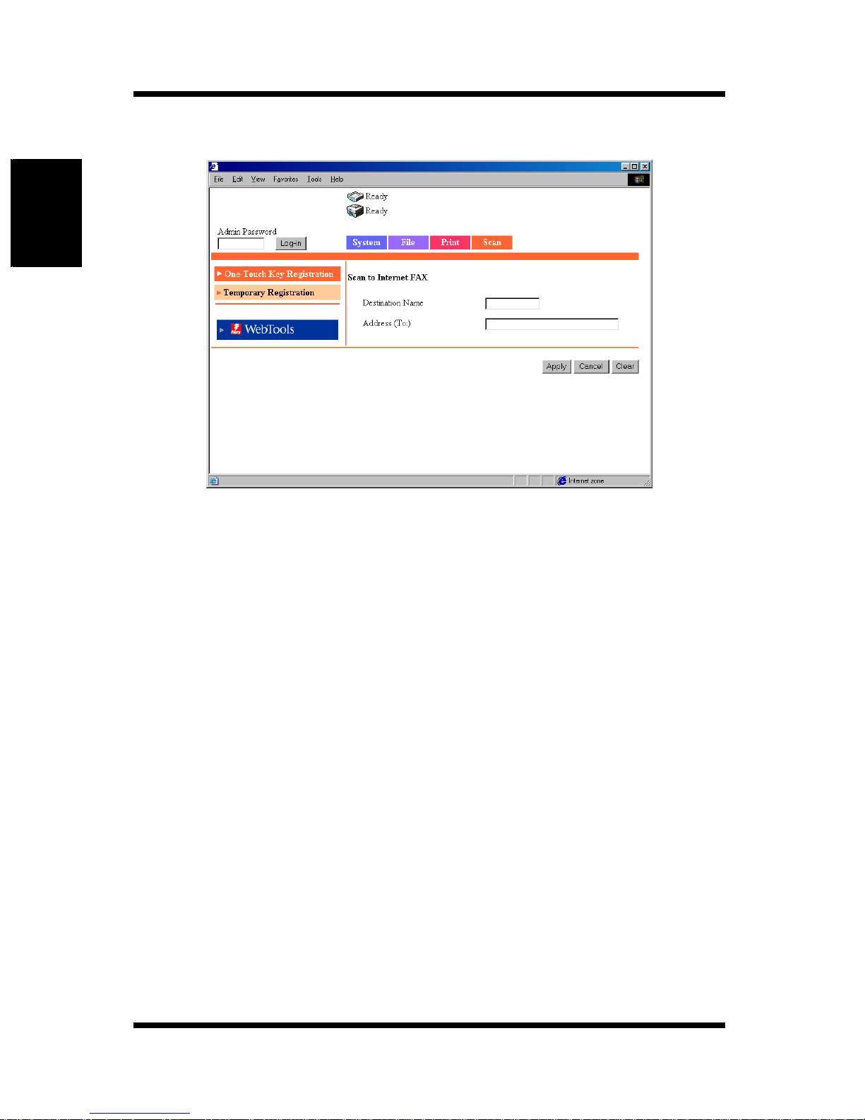
When Scan to Internet FAX is selected
Using the Scanner Mode Chapter 2
Destination Name:
Enter the name of the one-touch key.
Setting Up to 12 characters
Address (To): En ter the transmission destination address.
Setting Up to 72 characters, one address
2-36
Page 86
2.14 Registering the One-Touch Key and Temporary Registration Key
When Scan to E-mail is selected (Group Registration)
Note
• Group registration is possible only on the [Index 8] mailbox.
• Up to 15 groups can be registered.
Destination Name:
Enter the name of the one-touch key.
Setting Up to 12 characters
Address (To): En ter the transmission destination address.
Setting Up to 1800 characters and up to 50 addresses
When Scan to Internet F AX is selected (Gro up Registration)
Note
• Group registration is possible only on the [Index 8] mailbox.
• Up to 15 groups can be registered.
Destination Name:
Enter the name of the one-touch key.
Setting Up to 12 characters
Address (To): En ter the transmission destination address.
Setting Up to 1800 characters and up to 50 addresses
Using the Scanner Mode Chapter 2
2-37
Page 87
2.14 Registering the One-Touch Key and Temporary Registration Key
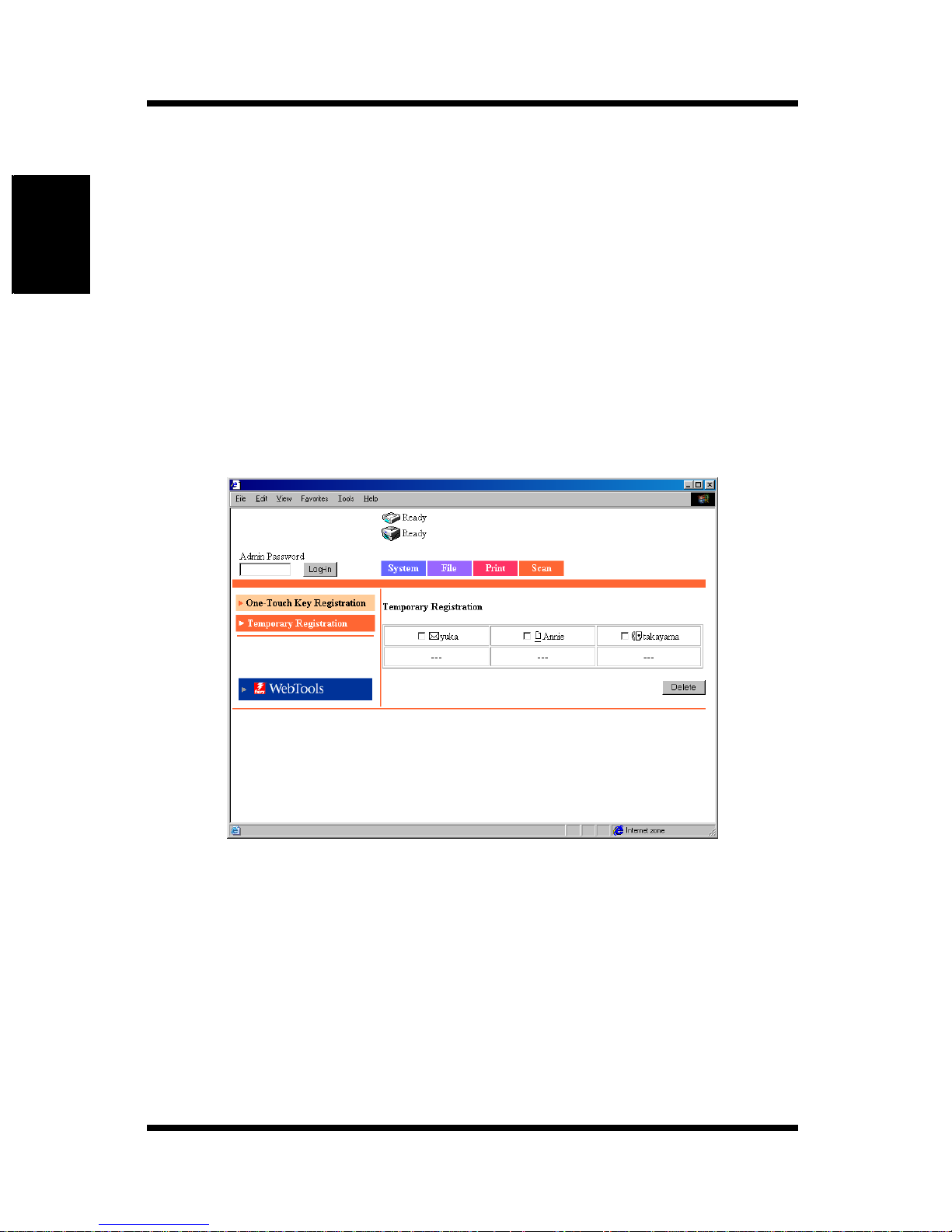
2.14.2 Temporary Registration Key
Registration
Temporary registration is entered using Printer Management Utility. The
difference from the one-touch registration is that the key is automatically
cleared after the transmission process is executed.
When registering a temporary registration key, you can enter the subject and
text of the mail and enter scan settings.
Setup procedure
1. Start Printer Management Utility.
2. Select [Temporary Registration] from the [Scan] tab.
Using the Scanner Mode Chapter 2
3. Click an unregistered box (---).
2-38
Page 88
2.14 Registering the One-Touch Key and Temporary Registration Key
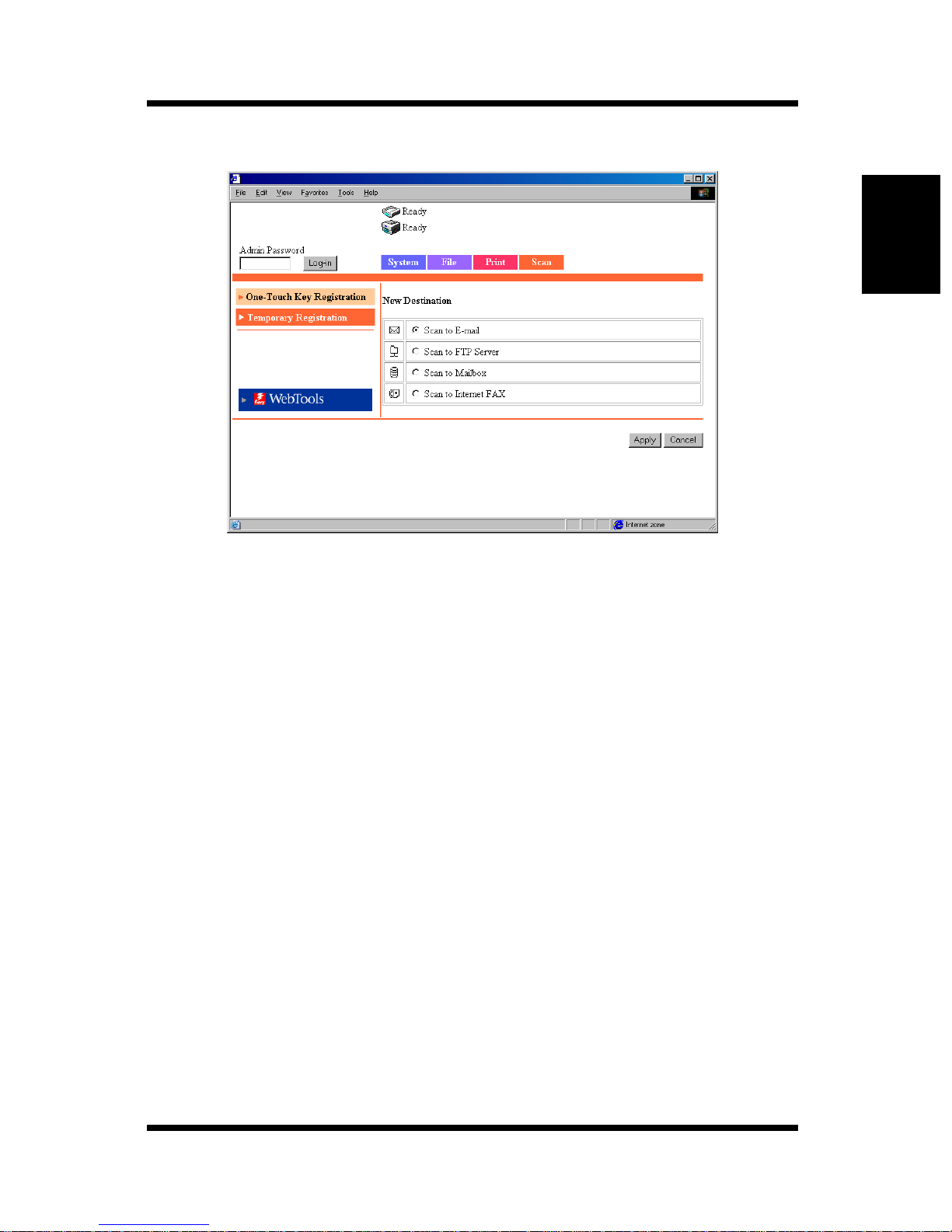
4. Select the transmission method.
5. Click [Apply]. The setup items corresponding to the transmission
method appear.
When Scan to E-mail is selected
Transmission Destinati on Set t in gs
Destination Name:
Enter the name of the temporary registration key.
Setting Up to 12 characters
Address (To): En ter the transmission destination address.
Setting Up to 1800 characters and up to 50 addresses
Subject: Enter the subject.
Setting Up to 64 characters
Text: Enter the mail text to be transmitted.
Setting Up to 256 characters
Enter the following settings as necessary.
Using the Scanner Mode Chapter 2
2-39
Page 89

Using the Scanner Mode Chapter 2
2.14 Registering the One-Touch Key and Temporary Registration Key
Scan Mode Settings
The scan mode settings below can also be entered from the copier operation
panel. (For the possible settings of each item, see Setup Items for Scanning
(p. 2-11).)
Original Mode: Specify the document scan mode.
Original Size: Specify the scan size of the document.
Resolution: Specify the resolution.
File Format (Data Format):
Specify the format of the image file.
Color Mode: Specify the color mode of the image file.
Background Remove:
Enter the background remove settings.
Orientation: Specify the image direction with the document set in
the ADF or Platen Grass.
Binding: Specify the direction of the margin of the document for
duplex printing.
Compression Level:
Specify the compression level of the image file.
Brightness: Specify the brightness of the document.
2-40
Page 90

2.14 Registering the One-Touch Key and Temporary Registration Key
When Scan to FTP Server is selected
Destination Name:
Enter the name of the temporary registration key.
Setting Up to 12 characters
IP Address: Set the IP address of the FTP server.
User Name: Enter the name used to log into the FTP server.
Password: Enter the password used to log into the FTP se rver.
Directory: Specify the location (directory) for storing the image
data on the FTP server.
(To speci fy the default folder, leave this blank.)
Use Default Proxy:
Set whether to use the proxy server.
Notification Address:
When using the e-mail notification function, enter the
destination mail address .
Using the Scanner Mode Chapter 2
Setting Up to 72 characters, one address
* Scan Mode Settings (same as for Scan to E-mail)
When Scan to Mailbox is selected
Destination Name:
Enter the name of the temporary registration key.
Setting Up to 12 characters
Mailbox Name :
Select the transmission destinatio n mailbox.
The list shows the mailboxes that have been registered
using [Mailbox] (p. 2-24).
Notification Address:
Enter the notification destination mail address.
Setting Up to 72 characters, one address
* Scan Mode Settings (same as for Scan to E-mail)
2-41
Page 91

2.14 Registering the One-Touch Key and Temporary Registration Key
When Scan to Internet FAX is selected
Destination Name:
Enter the name of the temporary registration key.
Setting Up to 12 characters
Address (To): En ter the transmission destination address.
Setting Up to 1800 characters and up to 50 addresses
Subject: Enter the subject.
Setting Up to 64 characters
Text: Enter the mail text to be transmitted.
Setting Up to 256 characters
The Scan Mode setup items are th e same as those for mail transmission ex cept
the following items.
Resolution: 200 × 200 dpi (fixed)
Using the Scanner Mode Chapter 2
File Format: TIFF (fixed)
Color Mode: Black & White
Orientation: No setup item
Compression: No setup item
2-42
Page 92
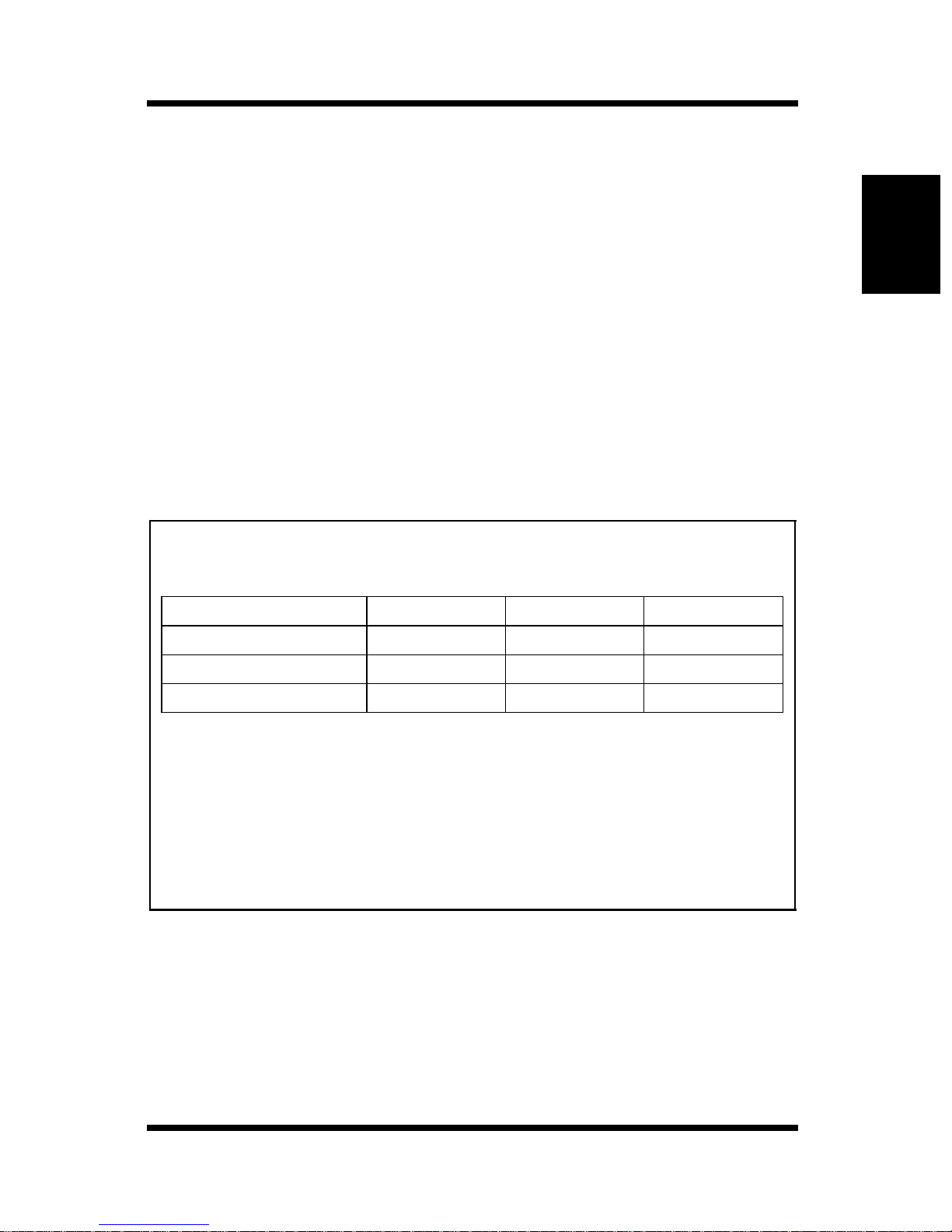
2.15 Image Data
2.15Image Data
The image data created by the scan function are described below.
2.15.1 File Format
You can select the file format of the image data from TIFF, PDF, and JPEG.
The following extension is added to the file name depending on the file
format.
TIFF Î .tif
PDF Î .pdf
JPEG Î .jpg
Note
• Some file formats cannot be specified depending on the selected color
mode.
PDF TIFF JPEG
Full color
Grayscale
Monochrome
• When transmitting image data using Internet FAX, only the TIFF format
can be selected.
• If yo u sc a n m u l ti pl e pa ge s of th e document when JPEG format is
selected, the data is divided into files by pages and attached to the mail.
Example: If 10 pages of the document are scanned, 10 JPEG files are
created and attached to the mail. (Ten JPEG files are attached to a
single mail.)
{{{
{{{
{{
—
Using the Scanner Mode Chapter 2
2-43
Page 93
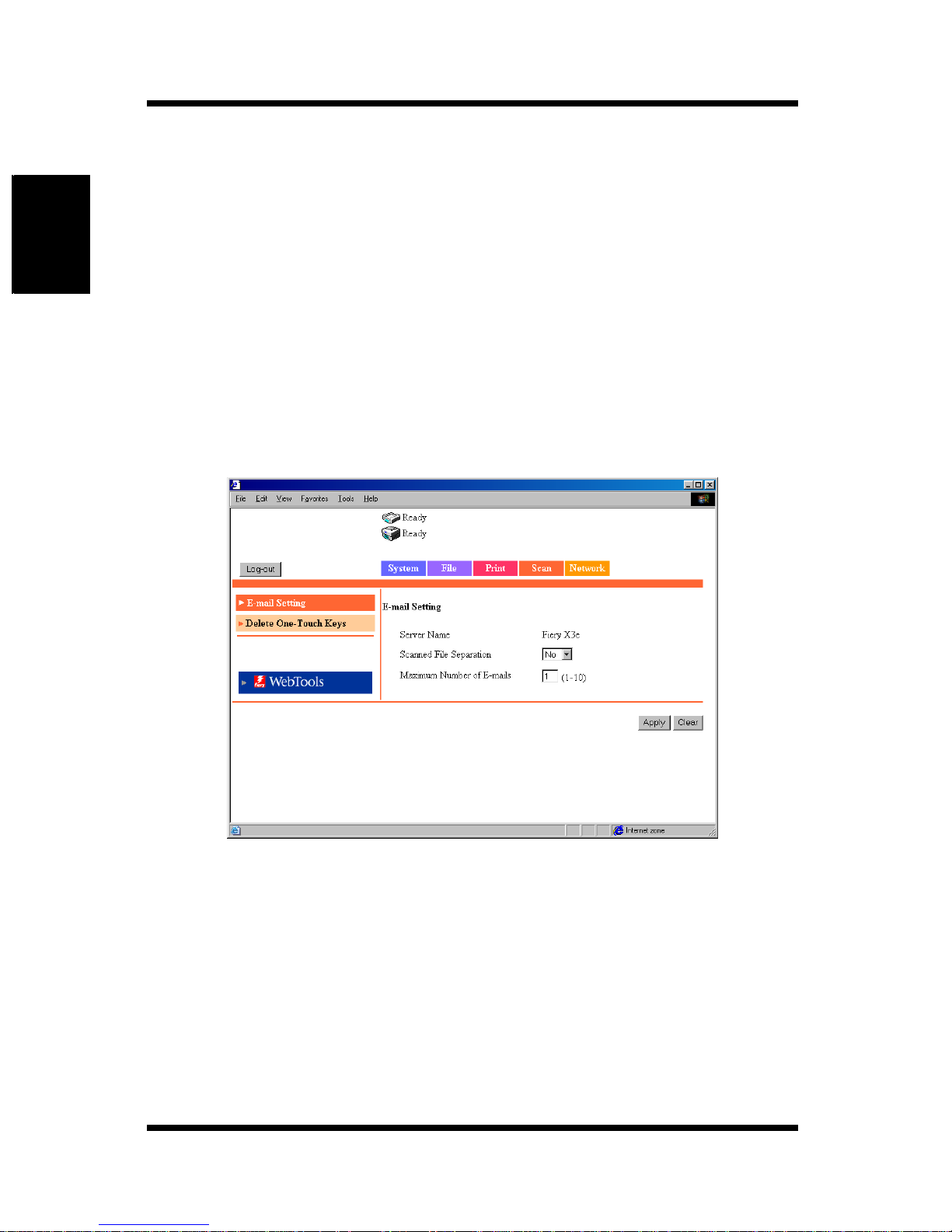
2.15 Image Data
2.15.2 File Name
The file name of the image data is automatically assigned by the controller.
The file name is assigned according to the following rule.
<Server name><automatic number><the number of pages in the
document
* When the mail is segmented for transmission, the last page number of the
attached files is used as a portion of the file names.
You can check the <Server name> by carrying out the following steps.
1. Start Printer Management Utility.
2. Log into the Administrator Mode.
3. Click the [Scan] tab.
*
>.extension
Using the Scanner Mode Chapter 2
2-44
Page 94

2.15 Image Data
Note
• The “Server Name” shown in Printer Management Utility corresponds to
the text specified in “Server Name” on the controller operation panel.
You can check “Server Name” on the controller operation panel by
carrying out the following steps.
1.Show the setup screen from the controller operation panel.
2.Select [Server Setup] — [Server Name] and check the server name.
• The automatic number is automatically assigned by the controller and
cannot be specified.
• File name example: Server name: test, automatic number: 50, the
number of pages in the document: 35, and PDF file
The file name is test50p35.pdf.
Using the Scanner Mode Chapter 2
2-45
Page 95

Using the Scanner Mode Chapter 2
2.16 Hold Period of the Image Data
2.16Hold Period of the Image Data
If the number of image data files held in the controller HDD keeps increasing,
there is a possibility that the disk becomes full. You can set the hold period of
the image data in the HDD by carrying out the following settings.
Note
Cases in which the image data is held in the HDD
• When using Scan to Mailbox
The image data is transferred to the HDD and held in the Mailbox
created in the HDD.
• When the size of the mail exceeds the upper limit specified by
[Maximum Scan File Size] on the mail function (see p. 2-21)
• When the upper mail limit specified by [Maximum Scan File Size] is
exceeded even after separating the data up to the number specified by
[Maximum Number of E-mails] when the data is separated because th e
[Maximum Scan File Size] is exceeded in the mail transmission function
(see p. 2-21, p. 2-22)
1. Show the setup screen from the controller operation panel.
2. Select [Server Setup] and enter the following settings.
[Clear Each Scan Job]:
Select the hold period. The image data is automatically
cleared when the hold period elapses.
Settings After 1 day, Now, Manually, After 1week
2-46
Page 96
2002. 10
The information contained in this manual is
subject to change without notice to
incorporate improvements made on the
product or products the manual covers.
 Loading...