

Fiery E-41 Installation And Service Manual

Color Controller E-41
Installation and Service Guide
A guide for service technicians
Replacement parts and specifications are
subject to change. For a current parts list,
contact your authorized service/support center.
Part Number: 45092155
September 27, 2010

© 2010 Electronics for Imaging, Inc.
This documentation is protected by copyright, and all rights are reserved. No part of it may be reproduced or transmitted in
any form or by any means for any purpose without express prior written consent from Electronics for Imaging, Inc. (“EFI”),
except as expressly permitted herein. Information in this documentation is subject to change without notice and does not
represent a commitment on the part of EFI. The documentation is further covered by “Legal Notices” distributed with this
product, which can be found on the User Documentation CD. The documentation may be provided in conjunction with EFI
Software (“Software”) and any other EFI product described in the documentation. The Software is furnished under license and
may only be used or copied in accordance with the terms of the EFI Software End User License Agreement, which can be
found in the “Legal Notices” distributed with this product.

CONTENTS
CONTENTS
CONTENTS 3
PREFACE 9
E-41 customer media pack 9
About the documentation 10
Service documentation 10
Customer documentation 10
About this guide 11
About the illustrations in this guide 11
Terminology and conventions 12
Precautions 14
Creating an ESD safe environment 16
Tools you will need 18
INTRODUCTION 19
Features 19
How the E-41 operates 20
INSTALLATION 22
Installation sequence 22
Checking the customer site 24
Setting customer expectations 25
Unpacking the E-41 26
Connecting the E-41 28
Completing installation and starting up 31

CONTENTS 4
USING THE E-41 32
Overview 32
Using the E-41 Control Panel 32
Buttons 33
Activity light 33
E-41 Control Panel Functions menu 34
Using the copier/printer display panel 35
Main tab 35
Job List tab 35
Too l s t ab 36
Scan tab 36
Fiery tab 37
Printable Info menu 38
Network Status LEDs 39
Starting, shutting down, restarting, and rebooting 40
Configuring a Static IP Address 41
SERVICE PROCEDURES 44
Overview 44
E-41 overview diagrams 45
Accessing internal components 49
Shutting down the system 49
Opening the E-41 51
Removing and replacing boards 56
Video board 56
User Interface Board assembly 58

CONTENTS 5
Motherboard 61
Removing the motherboard 61
Replacing the motherboard 65
Verifying new motherboard installation and transferring options 70
Replacing parts on the motherboard 77
DIMMs 77
CPU 79
Battery 84
Clearing the CMOS 85
Jumpers 85
Fan 86
Power supply 87
Hard disk drive 91
Switch bank assembly 97
DVD drive 101
Restoring and verifying functionality after service 104
SYSTEM AND USER SOFTWARE 105
Overview 105
Before you install system software 105
Installing system and user software 107
Backing up and restoring the E-41 Setup Configuration 110
Updating E-41 system and user software 111
Before updating the E-41 111
System Updates 112
Check for Product Updates (Software Downloads Site) 118

CONTENTS 6
TROUBLESHOOTING 120
Troubleshooting process 120
Preliminary on-site checkout 121
Checking external connections 122
Checking internal components 123
Inspecting the system 124
Normal startup sequence 129
Error messages and conditions 130
Diagnostic tools 142
Video board diagnostics 142
Test E-mail 143
SPECIFICATIONS 144
Hardware features 144
Physical specifications 144
Networking and connectivity 145
User software 145
Safety and emissions compliance 145
SERVICING THE E-41 WITH FURNITURE 146
Procedures 146
INDEX 157

LIST OF FIGURES
LIST OF FIGURES
FIGURE 1: Printing system 19
FIGURE 2: E-41 functional diagram 21
FIGURE 3: Summary of installation steps and references 23
FIGURE 4: E-41 shipping contents 27
FIGURE 5: Affixing the decal to the copier/printer 27
FIGURE 6: E-41 connections 28
LIST OF FIGURES 7
FIGURE 7: Straight-through and crossover Ethernet cables 29
FIGURE 8: E-41 Control Panel 32
FIGURE 9: Front and back panels 45
FIGURE 10: Back panel and internal side view 46
FIGURE 11: Exploded view of E-41 components 47
FIGURE 12: Power and data cable connections in the E-41 48
FIGURE 13: Removing/replacing the side panels 52
FIGURE 14: Removing/replacing the front panel 53
FIGURE 15: Removing/replacing the top panel 54
FIGURE 16: Diagram of the video board 56
FIGURE 17: Diagram of the User Interface Board (front and back) 58
FIGURE 18: Removing/replacing the User Interface Board 59
FIGURE 19: Removing/replacing the UIB buttons 60
FIGURE 20: Diagram of the E-41 motherboard 62

LIST OF FIGURES 8
FIGURE 21: Removing the motherboard 64
FIGURE 22: Connecting the dongle 71
FIGURE 23: Motherboard DIMM sockets 77
FIGURE 24: Releasing a DIMM 78
FIGURE 25: CPU cooling assembly 79
FIGURE 26: Removing/replacing the CPU 81
FIGURE 27: Inspecting the cooling assembly pins on the underside of the motherboard 83
FIGURE 28: Motherboard battery 84
FIGURE 29: Removing the fan 86
FIGURE 30: Removing/replacing the power supply 89
FIGURE 31: E-41 HDD 92
FIGURE 32: Removing/replacing the HDD bracket 93
FIGURE 33: Removing/replacing the HDD from/in the HDD bracket 94
FIGURE 34: Component Sled with switch bank assembly 97
FIGURE 35: Removing/replacing the Component Sled from the chassis 98
FIGURE 36: Removing/replacing the switch bank assembly 99
FIGURE 37: E-41 DVD drive 101
FIGURE 38: Removing/replacing the DVD drive 102
FIGURE 39: Troubleshooting the system 120
FIGURE 40: E-41 external cable connections 122
FIGURE 41: Normal startup sequence 129
FIGURE 42: E-41 installed on the furniture 146

PREFACE
PREFACE 9
The Installation and Service Guide is intended for authorized E-41 and copier/printer service
technicians installing or servicing the Color Controller E-41. If you are not an authorized
service technician, do not attempt to install or service the Color Controller E-41. Electronics
for Imaging, Inc. does not warrant the performance of the server if it is installed or serviced by
non-authorized personnel.
NOTE: The term “E-41” is used throughout this guide to refer to the Color Controller E-41.
The term “copier/printer” is used throughout this guide to refer to the Pro C901/C901S.
E-41 customer media pack
The E-41 customer media pack contains the following:
• System Software media (for service use only; multiple languages; includes the
Microsoft Windows XP Pro for Embedded Systems operating system software
and Fiery Server Software)
•User Software media
• Ricoh PCL Driver CD
• Fiery Options Utility (for service use only)
• Fiery Clone Tool (for service use only; includes documentation)
• User Documentation CD
•Printed We lc om e document
•Printed Secure Erase Administration Guide
•Printed Release Notes
•Other documentation

PREFACE 10
About the documentation
The documentation for the E-41 is described in the following sections.
Service documentation
The scope of the Installation and Service Guide is limited to describing how to install E-41
hardware and system software and how to service and troubleshoot the E-41. The
Troubleshooting chapter focuses on the individual components of the E-41 hardware, as well
as the E-41 connection to the network and copier/printer.
Details about the copier/printer, network, remote computers, software applications,
and Microsoft Windows operating system software are beyond the scope of this guide.
For details about the content, terminology, and conventions of this guide, see the sections
beginning on page 11.
Customer documentation
Customer documentation (also known as “user documentation”) is designed primarily
for users and administrators. It also contains information that may be useful to service
technicians; therefore, cross-references to the customer documentation are included in the
Installation and Service Guide.
Service technicians can obtain user documentation from the User Documentation CD.
Client users can obtain user documentation by using a Web browser to download
documentation files from the E-41. The documents are provided as Adobe Acrobat PDF
(Portable Document Format) files, which are indexed and cross-referenced. In addition, some
E-41 utilities (such as Command WorkStation) offer built-in Help.
For a complete description of the E-41 user documentation, see Welcom e on the User
Documentation CD.

PREFACE 11
About this guide
The Installation and Service Guide is organized into the following topics:
•Preface
General information, including a list of precautions.
• Introduction
General description of the E-41.
• Installation
Checking the customer site and unpacking the E-41; installing and connecting the E-41.
• Using the E-41
Overview of the E-41 functions and user interfaces; printing system pages; shutting down
and restarting the E-41.
• Service Procedures
Removal and replacement procedures for E-41 components; restoring and verifying
functionality.
• System and user software
Overview of the system software; installing system and user software; backing-up and
restoring configuration settings; updating system and user software.
• Troubleshooting
Common problems and ways of correcting them; startup error messages; general system
error conditions.
• Specifications
E-41 specifications.
• Servicing the E-41 with furniture (FACI option)
Assembly and disassembly instructions for systems that are mounted on the optional
furniture with the optional monitor attached.
NOTE: The E-41 Installation and Service Guide is not intended for customer use. Do not leave
the Installation and Service Guide at the customer site after servicing the E-41.
About the illustrations in this guide
Illustrations reflect the current shipping version of the E-41 at the time of publication.
Components shown in these illustrations are subject to change. To receive information about
any E-41 components that do not match the illustrations in this guide, contact your
authorized service/support center.

PREFACE 12
Terminology and conventions
The following sections explain the terminology and conventions used throughout this guide.
Service technician
In this guide, responsibilities attributed to the service technician may include the following:
• Making sure that the customer site has an appropriate electrical outlet and sufficient
physical space for the E-41
• Unpacking the E-41
• Installing and connecting the E-41
NOTE: The preceding functions may be performed by a trained rigger or service technician.
• Servicing the E-41 components
• Installing system and user software on the E-41
Network administrator
In this guide, responsibilities attributed to the network administrator include the following:
• Verifying that the customer site is network-ready
• Configuring E-41 Network Setup options
• Configuring the connection between the E-41 and the Command WorkStation
application installed on the E-41
• Installing the user software shipped with the E-41 onto the networked Windows and
Apple Mac OS computers that will print to it
• Configuring the connection between each remote computer and the E-41
PREFACE 13
E-41 components
The terms “replace” and “replacing” are used throughout this guide to mean the reinstallation
of existing components. Install new components only when necessary.
NOTE: Replacement parts and specifications are subject to change. When ordering
replacement parts, refer to the current parts list maintained by your authorized
service/support center. Install the correct parts as directed by your service/support center.
The term “Control Panel” refers to the area on the front of the E-41, including the green/red
activity light, the display window (LCD—liquid crystal display), and the buttons to the left
and right of the display window.
The term “LCD” refers to the display window of the E-41 Control Panel.
The term “monitor” refers to the optional E-41 flat panel monitor.
The term “DVD drive” (Digital Versatile Disk drive) refers to the E-41 DVD drive.
The term “system software” refers to the following software installed on the E-41 hard disk
drive (HDD):
• Windows XP Pro for Embedded Systems operating system software and Fiery Server
Software (System Software DVD)
• User Software (User Software DVD)
For other terms used to identify components of the E-41, see the reference key in Figure 11
on page 47.
Connectors and components labeled “not used”
Connectors and components labeled “not used” are disabled or are not used in the standard
E-41 configuration.
Document conventions
References to E-41 user documentation, such as Configuration and Setup, are displayed in
italics. The user documentation files are installed from the User Documentation CD.
NOTE: The note format highlights important messages and additional information.
The WARNING format indicates a potentially hazardous situation which, if instructions are
not followed, could result in death or serious injury. To use the E-41 safely, always pay
attention to these WARNINGs.
The CAUTION format indicates a caution concerning operations which, if not performed
correctly, may lead to injury. To use the E-41 safely, always pay attention to these
CAUTIONs.
The IMPORTANT format indicates operational requirements and restrictions. To operate
the E-41 correctly and avoid damage to the E-41 or other property, be sure to read the
IMPORTANT items carefully.
Precautions
• Avoid pressing the surface of the LCD.
• Use a soft cloth moistened with Lens and Mirror Cleaner to clean the surface of the E-41
• When connecting or disconnecting the power cord:
PREFACE 14
Always observe the following general precautions when installing and servicing the E-41:
Applying excessive pressure to the LCD window will cause it to change color.
display window.
Other solvents, such as water, may damage the polarizer on the display window.
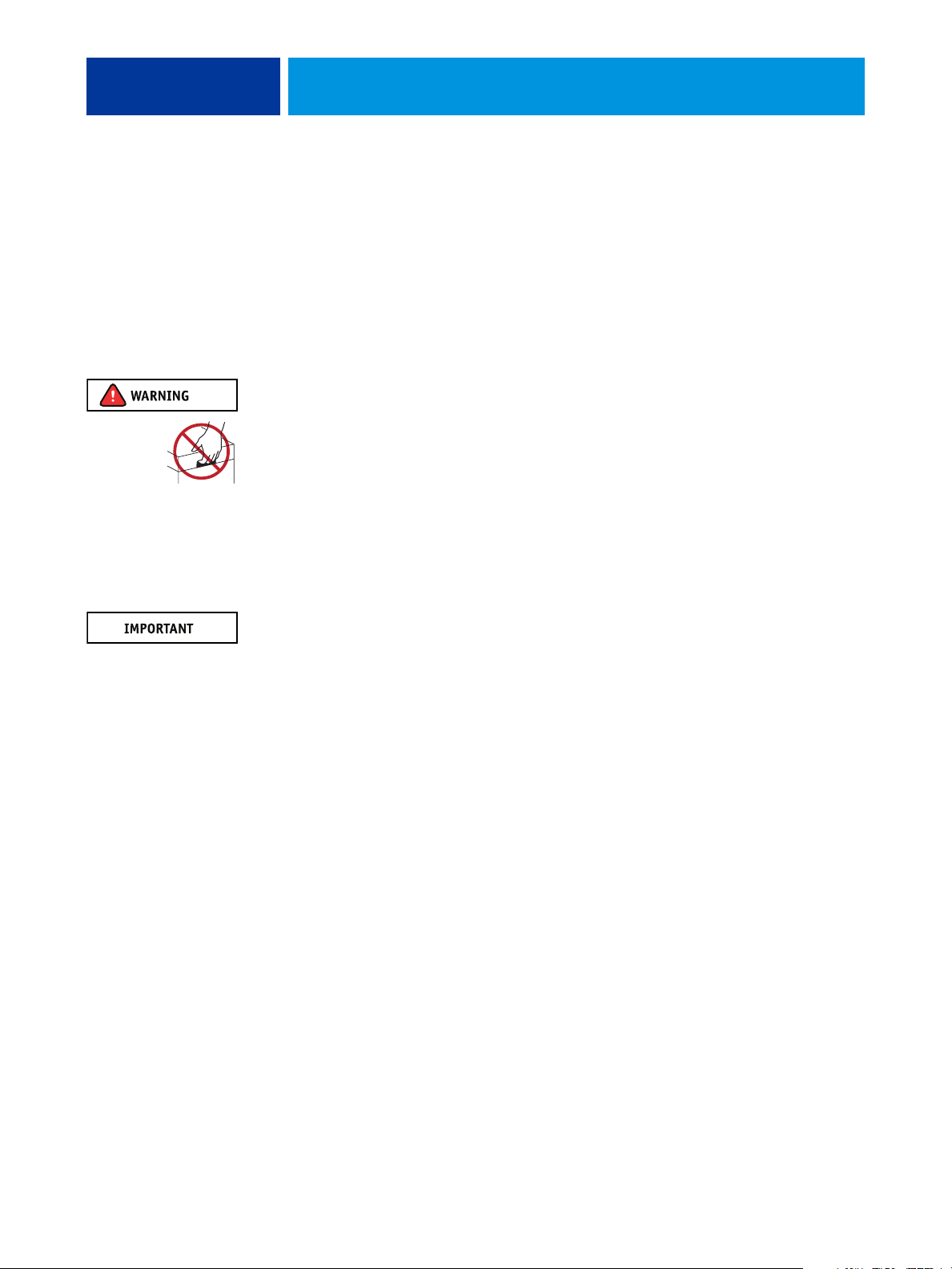
Never lift the E-41 by grasping the top panel. The top panel does not support the weight of
the system.
ATTENTION:
AVVERTENZA: Il server di stampa non deve essere mai sollevato afferrandolo dal pannello superiore, in quanto quest’ultimo non
può sostenere il peso dell’intero sistema.
WARNUNG: Heben Sie den Druckserver nicht an der oberen Gehäuseabdeckung an. Die obere Gehäuseabdeckung ist nicht dafür
ausgelegt, das Gesamtgewicht des Systems zu tragen.
DVERTENCIA: No levante nunca el servidor de impresión agarrándolo por el panel superior. El panel superior no soporta el peso
del sistema.
ADVERTÊNCIA: Nunca erga o servidor de impressão pelo painel superior. O painel superior não suporta o peso do sistema.
WAARSCHUWING: Til de afdrukserver nooit op door het bovenpaneel vast te nemen. Het bovenpaneel kan het gewicht van het
systeem niet dragen.
Ne jamais soulever le serveur d’impression par sa partie supérieure : celle-ci ne peut pas supporter le poids du système.
– Only use the power cord that shipped with the E-41 or an appropriate replacement power
cord available from an authorized provider.
– Always disconnect the power cord from the E-41 back panel before opening the unit and
servicing internal components.
– Do not pull on the power cord when unplugging the E-41. Pull the plug instead.
– Do not place objects on the power cord. Place the power cord away from foot traffic.
– Do not tamper with or disable the power cord grounding plug.
– Do not use a 3-prong adapter in a 2-hole ungrounded outlet.
– Do not use an extension cord.
– Do not plug the E-41 into a circuit with heating or refrigeration equipment (including
water dispensers).
– Do not plug the E-41 into a switchable power outlet. This can result in the E-41 being
turned off accidentally.
• Never set any liquid on or near the E-41 or copier/printer. If liquid is spilled into the E-41 or
copier/printer, disconnect the power cord immediately.
• Do not attempt to open the power supply, DVD drive, or hard disk drive (HDD).

PREFACE 15
• Handle the E-41 LCD window with care.
If the E-41 LCD window breaks and the liquid crystal inside leaks out, avoid contact with it.
If you come in contact with the liquid crystal, wash it off your skin immediately with soap
and water.
• Use care when handling parts of the E-41, as some edges on the unit may be sharp.
• Do not install third-party applications onto the E-41. Third-party applications are not
supported and can cause system problems. Although virus scans are permitted on the E-41,
virus-protection software should not be loaded in memory-resident mode.
• Do not change the Windows operating system software preference settings.
Depending on the changes made, the E-41 may become unstable or even unusable. If this
occurs, we recommend that you reinstall the E-41 System Software, which reliably restores the
Windows operating system software to its factory defaults.
• Never alter an existing network without permission.
The E-41 will probably be connected to an existing Local Area Network (LAN) based on
Ethernet hardware. The network is the link between the customer’s computer, existing laser
printers, and other prepress equipment. Never disturb the LAN by breaking or making a
network connection, altering termination, installing or removing networking hardware or
software, or shutting down networked devices without the knowledge and explicit permission
of the system or network administrator or shop supervisor.
• Unless you are the network administrator, never assign an IP address in E-41 Network Setup.
In a DHCP environment, the system assigns the IP address automatically. In a non-DHCP
environment, you should enter only the IP address that has been assigned by the network
administrator. Only the network administrator should assign an IP address to a network
device. Assigning the E-41 an incorrect IP address may cause unpredictable errors on any or
all devices connected to the network.

PREFACE 16
Creating an ESD safe environment
• Follow standard ESD (electrostatic discharge) precautions while working on the internal
components of the E-41.
Static is always a concern when servicing electronic devices. It is highly unlikely that the area
around the copier/printer and the E-41 is static-free. Carpeting, leather-soled shoes, synthetic
clothing fibers, silks, and plastics may generate a static charge of more than 10,000 volts.
Static discharge is capable of destroying the circuits etched in silicon microchips, or
dramatically shortening their life span. By observing standard precautions, you may avoid
extra service calls and save the cost of a new board.
When possible, work on a ground-connected antistatic mat. Wear an antistatic grounding
strap, grounded at the same place as the antistatic mat. If that is not possible, do the
following:
• Attach a grounding strap to your wrist. Attach the other end to a good ground.
• When you unpack the E-41 from the carton for the first time, touch a metal area of the
copier/printer to discharge the static on your body.
• Before you remove any of the E-41 panels and handle internal components, touch a metal
part of the E-41.
• Leave new electronic components inside their antistatic bags until you are ready to install
them. When you remove components from an antistatic bag, place them on a grounded
antistatic surface, component-side up.
• When you remove an electronic component, place it in an antistatic bag immediately.
Do not walk across a carpet or vinyl floor while carrying an unprotected board.
• During service to the motherboard, avoid using excessive force and always place the
motherboard on a grounded, non-metallic, static-free surface. Never allow any metal to
touch the solder contacts on the underside of the motherboard, especially beneath the
battery socket. Improper handling can short-circuit and permanently damage the
motherboard.
• Handle printed circuit boards by their opposing edges only and avoid touching the contacts
on the edge of the board.
PREFACE 17
Power Supply Cord Notice
The power supply cord is used as the main disconnect device. Ensure that the socket-outlet is
located/installed near the equipment and is easily accessible.
ATTENTION: Le cordon d’alimentation doit être débranché pour une mise hors tension totale du produit. La prise de courant doit
être située ou installée à proximité du matériel et être facilement accessible.
ATTENZIONE: Il cavo di alimentazione deve essere scollegato per interrompere completamente la corrente. Accertarsi che la presa
di corrente si trovi o sia installata vicino alla macchina e sia facilmente accessibile.
ACHTUNG: Der Netzstecker dient zur sicheren Trennung des Gerätes von der Stromversorgung. Stellen Sie sicher, dass
sich die Steckdose in unmittelbarer Nähe des Gerätes befindet und leicht zugänglich ist.
CUIDADO: El cable de alimentación eléctrica se utiliza como dispositivo de desconexión principal. Asegúrese de que el enchufe-
toma esté situado/instalado cerca del equipo y que sea fácilmente accesible.
CUIDADO: O cabo de força é usado como dispositivo principal de desconexão. Assegure-se de que a saída de energia
esteja localizada/instalada próxima ao equipamento e facilmente acessível.
VOORZICHTIG: Het netsnoer moet worden uitgetrokken om de stroomvoorziening te onderbreken. Zorg ervoor dat het
stopcontact zich dicht bij het apparaat bevindt en gemakkelijk toegankelijk is.
Lithium Battery Notice
There is a danger of explosion if the battery is replaced with an incorrect type. Replace a
battery only with the same type recommended by the manufacturer. Dispose of used batteries
according to local regulations.
ACHTUNG: Es besteht Explosionsgefahr, wenn die Batterie durch eine Batterie falschen Typs ersetzt wird. Als Ersatz dürfen nur
vom Hersteller empfohlene Batterien gleichen oder ähnlichen Typs verwendet werden. Verbrauchte Batterien müssen entsprechend
den jeweiligen gesetzlichen Bestimmungen entsorgt werden.
ATTENTION: Il y a risque d’explosion si la pile est remplacée par un modèle qui ne convient pas. Remplacez-la uniquement par le
modèle recommandé par le constructeur. Débarrassez-vous des piles usées conformément aux réglementations locales en vigueur.
ADVARSEL!: Litiumbatteri - Eksplosionsfare ved fejlagtig håndtering. Batteriet må kun udskiftes med et andet batteri af samme
fabrikat og type. Brugte batterier skal bortskaffes i henhold til gældende regler.
VAROITUS: Paristo voi räjähtää, jos se on vaihdetaan väärän tyyppiseen paristoon. Vaihda paristo ainoastaan laitevalmistajan
suosittelemaan tyyppiin. Hävitä käytetty paristo paikallisten määräysten mukaisesti.
ADVARSEL: Eksplosjonsfare ved feilaktig skifte av batteri. Benytt samme batteritype eller en tilsvarende type anbefalt av
apparatfabrikanten. Brukte batterier kasseres i henhold til lokal lovgivning.
VARNING: Risk för explosion om batteriet byts ut mot en felaktig batterityp! Byt bara ut batteriet mot en batterityp som har
godkänts av tillverkaren. Hantera använda batterier enligt lokal miljölagstiftning.
CUIDADO: Existe peligro de explosión si la batería se sustituye por una batería del tipo incorrecto. Sustituya la batería sólo por una
batería del mismo tipo que recomienda el fabricante. Deseche las baterías usadas respetando la normativa local.
ATTENZIONE: Esiste pericolo di esplosione se la batteria viene sostituita con una di tipo non corretto. Sostituirla solamente con un
tipo raccomandato dal produttore. Lo smaltimento delle batterie usate deve essere eseguito secondo le normative locali.
AVISO: Existe o perigo de explosão se a bateria for substituída por uma do tipo incorreto. Substitua somente por uma do tipo
recomendado pelo fabricante. Descarte as baterias conforme as normas locais.
GEVAAR: Er bestaat ontploffingsgevaar indien de batterij door een verkeerd type wordt vervangen. Vervang de batterij uitsluitend
door hetzelfde door de fabrikant aanbevolen type. Ruim gebruikte batterijen op volgens de plaatselijke voorschriften.
PREFACE 18
Short Circuit Protection
This product relies on the building’s installation for short-circuit (overcurrent) protection.
Ensure that a fuse or circuit breaker no larger than 120 VAC, 15A U.S. (240 VAC, 10A
international) is used on the phase conductors (all current-carrying conductors).
ATTENTION : La protection contre les courts-circuits (surtension) du produit est assurée par l’installation électrique du local où il
est installé. S’assurer qu’un fusible ou un disjoncteur inférieur ou égal à 120 V CA , 15 A aux Etats-Unis (240 V CA, 10 A dans les
autres pays) est utilisé pour les conducteurs de phase (conducteurs de courant).
AVVERTENZA: La protezione contro i short-circuit (sovracorrente) del prodotto dipende dall’impianto elettrico dell’edificio in cui
è installato. Accertarsi che sui conduttori di fase (che portano la corrente) venga utilizzato un fusibile o interruttore non superiore a
120 Vc.a., 15 A negli Stati Uniti (240 Vc.a., 10 A internazzionale).
WARNUNG: Dieses Produkt ist darauf angewiesen, dass im Gebäude ein Kurzschluss- bzw. Überstromschutz installiert ist. Stellen
Sie sicher, dass eine Sicherung oder ein Unterbrecher von nicht mehr als 240 V Wechselstrom, 10 A (bzw. in den USA 120 V
Wechselstrom, 15 A) an den Phasenleitern (allen stromführenden Leitern) verwendet wird.
DVERTENCIA: Este producto depende de la instalación del edificio en lo relativo a la protección frente a cortocircuitos
(sobretensión). Asegúrese de utilizar un fusible o un interruptor de circuito que no sea de más de 120 V CA, 15A en EE.UU.
(240 V CA, 10A internacional) en los conductores de fase (todos los conductores que transportan corriente).
ADVERTÊNCIA: Esse produto depende da instalação de proteção contra curto-circuito (sobrecarga) do edifício. Assegure-se de que
um fusível ou disjuntor de até 120 VAC, 15A U.S. (240 VAC, 10 A internacional) seja usado nos condutores de fase (todos os
condutores de corrente).
WAARSCHUWING: Dit apparaat wordt tegen kortsluiting (overstroom) beveiligd via de elektrische installatie van het gebouw.
Zorg ervoor dat de fasegeleiders (alle stroomvoerende geleiders) beveiligd zijn met een zekering of stroomonderbreker met
een maximale capaciteit van 120 V wisselstroom, 15 A in de V.S. (240 V wisselstroom, 10 A internationaal).
Tools you will need
To install or service the E-41, you will need the following tools and parts:
• ESD wrist grounding strap and antistatic mat
• Flathead screwdriver
• #0, #1, and #2 Phillips head screwdrivers
• Needlenose pliers
• E-41 documentation, including the customer media pack and any related service bulletins
Avoid touching magnetic tools to storage media such as HDDs. Contact between magnetic
tools and magnetic storage media may result in data corruption.
INTRODUCTION
Features
INTRODUCTION 19
The E-41 adds computer connectivity and highly efficient Adobe PostScript 3 color printing
capability to the copier/printer. It is optimized for high-speed network communications,
processing, rasterization, and printing of continuous tone color and monochrome pages.
The E-41, as an integral part of a color printing system, enables users to:
• Send images over AppleTalk and TCP/IP networks to E-41 supported devices.
• Spool print jobs and select a printing priority for each job. Users can control spooled print
jobs sent to the E-41 with remote user software running on networked Windows and Mac
OS computers.
• Print color, grayscale, and black-and-white jobs.
• Use the copier/printer as a high-resolution color scanner with Fiery Scan software.
• Use 136 resident fonts (126 Adobe Type 1 PostScript, and 10 TrueType), plus several
Adobe Multiple Master fonts used for font substitution when printing PDF files.
Command WorkStation or any third-party LaserWriter downloader, such as the Adobe
Font Downloader, can be used to download additional fonts.
• Use built-in ColorWise color management and NetWise network features.
The E-41 also supports the Microsoft version of Internet Printing Protocol (IPP) for
Windows XP, Windows Vista, Windows Server 2003/2008/2008 R2, Windows 7, and e-mail
printing.
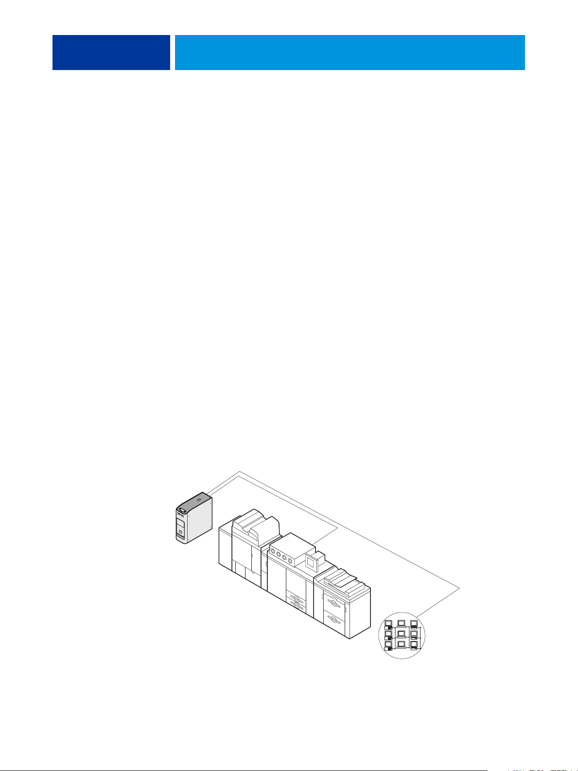
The E-41 is one of several imaging products
engineered and manufactured by
Electronics for Imaging, Inc.
E-41
Copier/printer
FIGURE 1: Printing system
Networked computers
or workstations

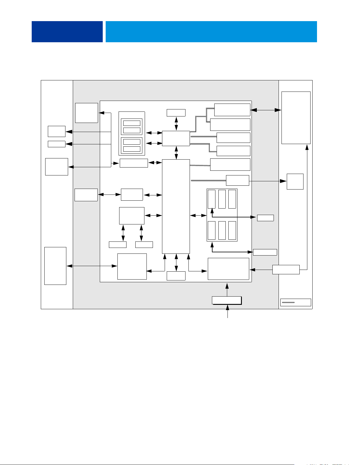
INTRODUCTION 20
How the E-41 operates
The E-41 enables the customer to use the copier/printer as a high-performance, networked
PostScript color printer and scanner. Users at the customer site can print to the E-41 from
networked Windows computers, Mac OS computers, and networked UNIX workstations
running TCP/IP.
The E-41 custom-designed boards and system software provide efficient image processing and
printing controls. The main functions of E-41 components and software are described in the
following paragraphs.
The E-41 uses the motherboard and a custom video board to process image data for printing
and scanning images.
The motherboard includes an Intel Core 2 Duo E8400 3.0GHz CPU that controls the image
data transfer to and from the motherboard and runs the interpreter. The interpreter rasterizes
the page description file and compresses the image pattern into memory using compression
technology.
The interpreter outputs compressed raster data through the image frame buffer memory to
the E-41 video board. The video board decompresses the image data and sends it to the
copier/printer through a crossover copier/printer interface cable connected to the upper RJ-45
on the E-41 back panel. The raster data is supplied to the copier/printer, which then renders
the final image on paper at full rated engine speed.
High-speed DIMMs (dual in-line memory modules) on the motherboard hold the image data
during printing. The E-41 is configured with two 1GB DIMMs for a total of 2GB of
memory.
When Fiery Scan uses the copier/printer as a scanner, the E-41 acquires RGB (red, green, and
blue) image data from the copier/printer, stores it in memory, and transmits it to the
computer that requested the scan.
INTRODUCTION 21
External
devices
USB
devices
Dongles
Keyboard
and mouse
(option)
Networked
computers
User
interface
board
IDE
(not used)
Memory
DIMM 4
Empty
DIMM 2
Empty
USB 2.0 (x10)
USB to
ATA bridge
Super
I/O
RTC
Upper RJ-45
network
interface
1000BaseT
controller
Reset
E-41
Motherboard
CPU
North bridge
memory
controller
South bridge
I/O
controller
BIOS
PCI-E
PCI-X 133/100
PCI-E
PCI
SATA 2
SATA 1
Video board
PCI-E x 8 slots
x4 signal (not used)
PCI-X
(not used)
PCI-X
(not used)
PCI-E x 16 slots
x4 signal (not used)
Graphics
controller
SATA 4
SATA 6
SATA 3
SATA 5
Copier/printer
interface
(Lower RJ-45)
HDD
DVD drive
Copier/
printer
Monitor
(option)
Print & Scan
FIGURE 2: E-41 functional diagram
+3.3/+5/±12V DC
Power supply
AC power
PCI bus

INSTALLATION
INSTALLATION 22
This chapter includes information about the following:
• Installation sequence (see below)
• Checking the customer site (see page 24)
• Unpacking the E-41 (see page 26)
• Installing the E-41 and connecting it to the copier/printer and network (see page 28)
• Completing the installation (see page 31)
– Print a Test Page and Configuration page (page 37).
– Remind the site administrator to install current user software on networked computers
that print to the E-41 (see Printing and Utilities on the User Documentation CD).
Installation sequence
Familiarize yourself with this chapter before you attempt an installation. The installation
sequence described in this chapter is designed to make your job as easy as possible. Installation
problems are easier to avoid and diagnose if you proceed from the component to the system
level and verify functionality at each stage. Figure 3 on page 23 outlines the recommended
installation procedure for connecting the E-41 to the copier/printer.
Because the E-41 is a node on the customer’s computer network, make sure that you
coordinate your scheduled installation with the network administrator at the customer site.
For Network Setup information, refer the network administrator to Configuration and Setup
on the User Documentation CD.
NOTE: You can change the default language preinstalled at the factory using the Configure
tool available through Command WorkStation and WebTools. Launch Configure and then
navigate to Server > General > Choose Server Language and then click Apply.
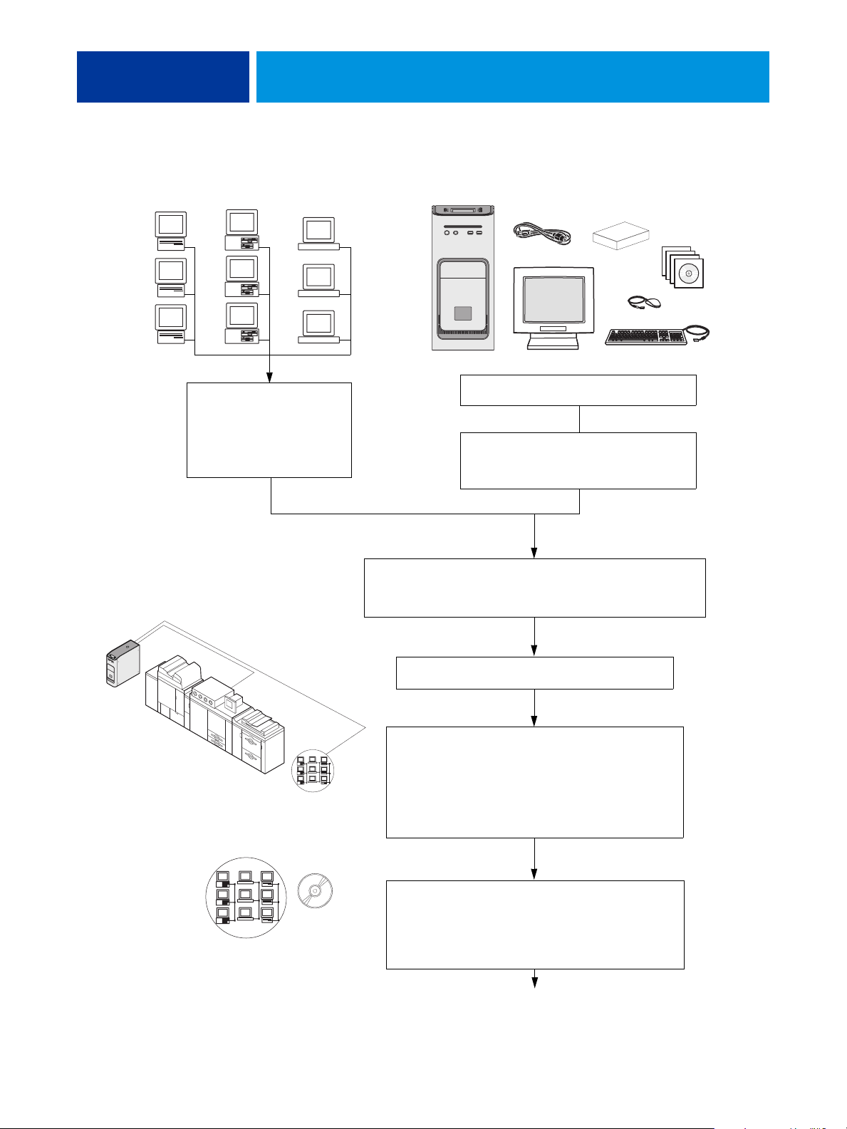
INSTALLATION 23
M
OS
PC
UNIX
ac
computers
computers
workstations
Check installation requirements
E-41
Power cable(s), customer kit, media pack,
optional monitor, keyboard, and mouse
Unpack the E-41 (see page 26).
and verify site conditions.
If possible, obtain verification
that the network is operational
(see page 24).
If present, connect the optional monitor,
keyboard, and mouse to the E-41
(see page 28).
If you must change the E-41 language, in Command WorkStation or
WebTools, launch Configure and then navigate to Server > General >
Choose Server Language, and then click Apply.
Copier/printer
Networked computers
Affix the Fiery decal to the copier/printer front cover.
Connect interface cables (see page 29):
• Network straight-through cable to the upper RJ-45 port
on the E-41 back panel and customer network.
• Ethernet crossover cable to the lower RJ-45 port on the
E-41 back panel and the Gigabit Ethernet connector on
the copier/printer.
Complete installation (see page 31).
Remind the site administrator to install the current
user software on networked computers that print to the
E-41 (see Printing and Utilities on the User Documentation
CD).
Full E-41 functionality
FIGURE 3: Summary of installation steps and references
INSTALLATION 24
Checking the customer site
Before you install the E-41, check site conditions and inform the customer of any installation
requirements.
Copier/printer readiness
Is the copier/printer configured for use with the E-41?
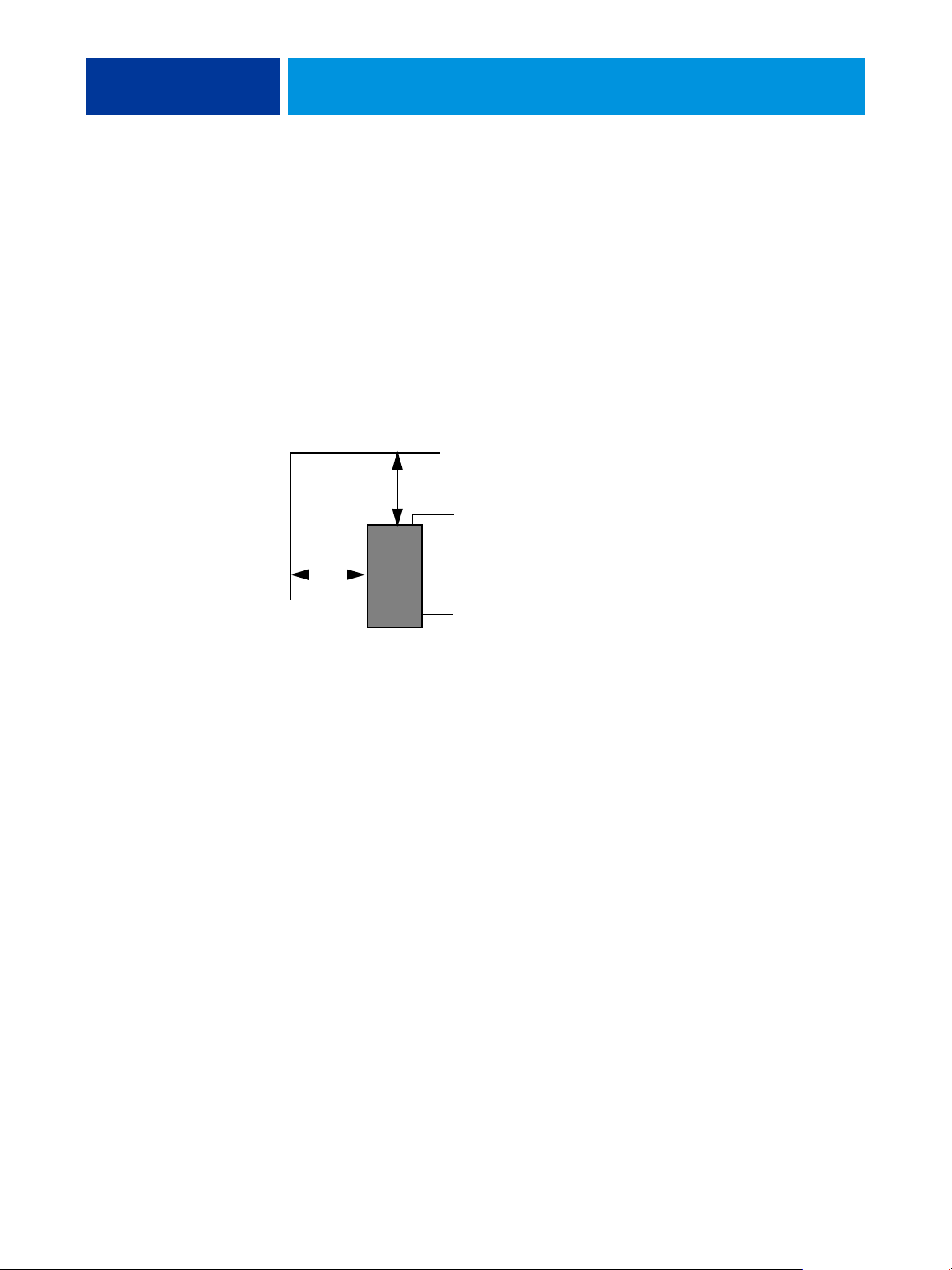
Is space available near the copier/printer for the E-41?
Make sure that adequate space is available for the E-41. Allow enough space at the back panel
for the cables to route easily and at the side panel so that the E-41 does not interfere with use
of or service to the copier/printer (such as clearing a paper jam). You may need to move the
copier/printer away from the wall so that the interface connectors are accessible.
20cm+ (8 in.)
Back panel
E-41
20cm+ (8 in.)
Side panel
Does the copier/printer require service or adjustments?
Print the copier/printer Test Page before you install the E-41.
If the image indicates that the copier/printer needs adjustment, inform the customer.
After getting approval, complete the necessary copier/printer service.
Power
Is a dedicated, grounded electrical outlet for the E-41 available near the copier/printer?
Locate the grounded electrical outlet that will supply power to the E-41. Do not run the E-41
and the copier/printer on the same circuit. Use a surge suppressor for the E-41 if the customer
has provided one.
• Do not use a 3-prong adapter in a 2-hole ungrounded outlet.
• Do not use an extension cord.
• Do not plug the E-41 into a circuit with heating or refrigeration equipment (including
water coolers).
• Do not plug the E-41 into a switchable wall outlet. This can result in the E-41 being
turned off accidentally.
• Do not pull on the cable when unplugging the E-41. Pull the plug instead.

INSTALLATION 25
Network
Make sure that the network will be available at the time set for installation.
Verify with the network administrator that the network is functioning before you attach
the E-41.
Make sure that the configuration requirements specified in Configuration and Setup
(on the User Documentation CD) have been met for remote computers and the network.
Setting customer expectations
When the site is ready, installation of the E-41 takes about one hour. Inform the customer of
the following:
• Some nodes on the network may be unavailable for up to one hour.
• The copier/printer may be unavailable for up to one hour.
• The network administrator must be available during the installation for network
connectivity.
Equipment downtime and impact on the network can be minimized if the network
administrator installs a network connector for the E-41 and confirms network
functionality with the connector in place before the date scheduled for the E-41
installation.
• The network administrator must make a networked computer available during the
installation. The appropriate software must be installed in advance. Documentation for
the networked computer and network operating software should be available.
• The network administrator must install the user software shipped with the E-41 onto
networked Windows and Mac OS computers that print to the E-41 (user documentation
is also included).
NOTE: This guide covers hardware installation and service and provides general information
about connecting the E-41 to the customer’s network. Network Setup and configuration
information exceeds the scope of this guide. For Network Setup and configuration
information, refer the network administrator to Configuration and Setup on the User
Documentation CD.
INSTALLATION 26
Unpacking the E-41
The E-41 is assembled and shipped from the factory with all necessary cables (except the
network cable) and documentation (see page 27).
Never lift the E-41 by grasping the top panel. The top panel does not support the weight of
the system.
AVERTISSEMENT: Ne jamais soulever le serveur d'impression par sa partie supérieure : celle-ci ne peut pas supporter le poids du système.
AVVERTENZA: Il server di stampa non deve essere mai sollevato afferrandolo dal pannello superiore, in quanto quest'ultimo non può
sostenere il peso dell'intero sistema.
WARNUNG: Heben Sie den Druckserver nicht an der oberen Gehäuseabdeckung an. Die obere Gehäuseabdeckung ist nicht dafür
ausgelegt, das Gesamtgewicht des Systems zu tragen.
ADVERTENCIA: No levante nunca el servidor de impresión agarrándolo por el panel superior. El panel superior no soporta el peso
del sistema.
AVISO: Nunca erga o servidor de impressão pelo painel superior. O painel superior não suporta o peso do sistema.
WAARSCHUWING: Til de afdrukserver nooit op door het bovenpaneel vast te nemen. Het bovenpaneel kan het gewicht van het
systeem niet dragen.
TO UNPACK THE E-41
1. Open the box and remove the packing material.
Save the original boxes and packing material in case you need to transport the E-41 at a later
date.
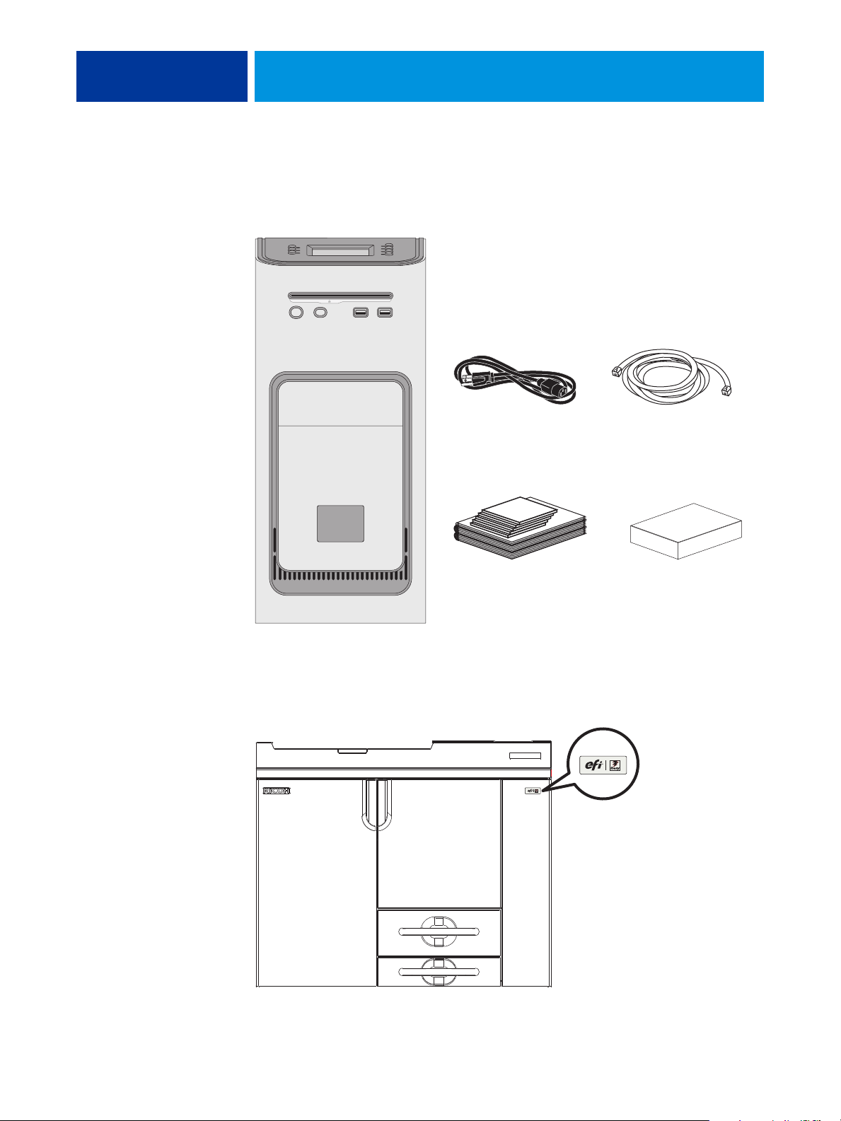
2. Remove the contents from the top container. Inspect the contents for visible damage. The top
container should include the following items:
• Bags containing the copier/printer interface cable (Ethernet crossover, 39.3 ft./12m) and
region-specific AC power cables
• Customer Kit containing the EFI/Fiery decal and other Ricoh-provided materials
• E-41 Setup Roadmap
• Customer media pack (includes disks for system software, user software,
Fiery Options Utility, user documentation, and other documentation)
3. Set aside the remaining components from the top container.
4. Remove the top container and any packing material.
Set aside the packing material and note the orientation of the E-41 inside the shipping
container, in case you need to repack it later.
5. Carefully lift the E-41 out of the box.
If you notice shipping damage to any component, save the shipping container in case the
carrier needs to see it. Call the carrier immediately to report the damage and file a claim.
INSTALLATION 27
6. Give the media pack to the customer or network administrator.
Let the customer or network administrator know that in order to take full advantage of the
E-41, the user software must be installed on computers that will print to the E-41.
Power cables (x5)
Customer media pack Customer Kit
Copier/printer interface cable
(Ethernet crossover, 39.3 ft.)
FIGURE 4: E-41 shipping contents
7. Locate the EFI/Fiery decal in the shipping container and affix it to the copier/printer as
shown.
EFI/Fiery decal
FIGURE 5: Affixing the decal to the copier/printer
INSTALLATION 28
Connecting the E-41
You are now ready to make the following connections:
• Optional monitor, keyboard, and mouse (if present)
• Optional dongle (if present)
• Power cable connection
• Copier/printer interface cable connection
• Network cable connection
For detailed information about the monitor, keyboard, and mouse, see the documentation
that accompanies the optional kit.
Follow standard ESD precautions when handling components.
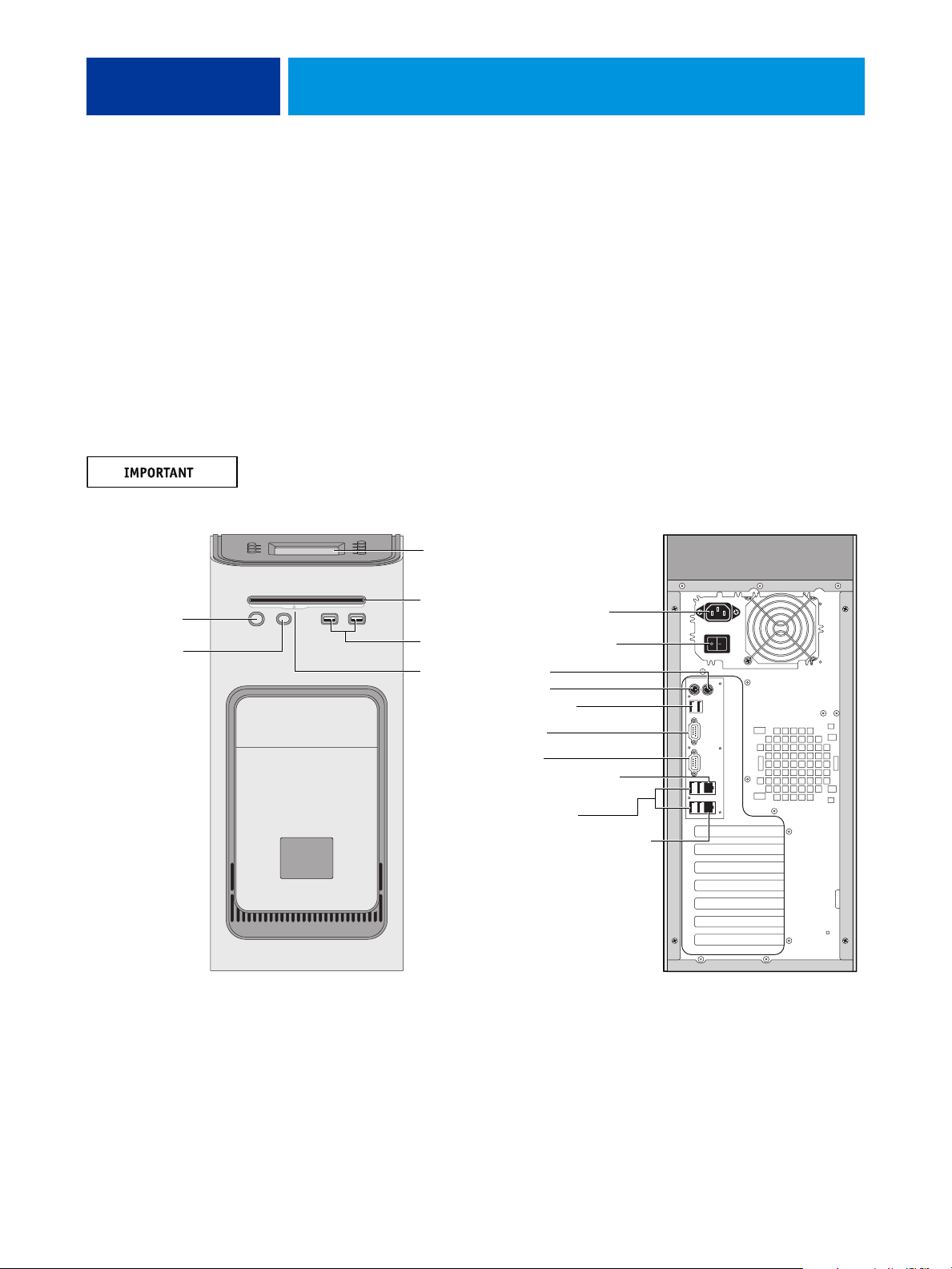
Power button
Reset button
NOTE: Use the
reset button only
if the system is
unresponsive to
keyboard or
mouse actions.
Control panel
DVD drive
USB ports
Eject button
Copier/printer interface (RJ-45):
Ethernet crossover cable
Front panel Back panel
Power cable
Power switch
Not used
Not used
USB ports (x2)
Not used
Monitor
Network port (RJ-45):
Straight-through cable
USB ports (x4)
FIGURE 6: E-41 connections
INSTALLATION 29
TO CONNECT POWER
1. Connect the recessed end of the E-41 power cable to the power connector on the back of the
E-41 (see Figure 6 on page 28).
2. Connect the other end of the E-41 power cable to a wall outlet.
Make sure to use the correct power cable for your region. Also, to prevent the risk of
cross-talk, make sure that the copier/printer interface cable does not touch the system power
cables. Otherwise, image quality problems or E-41 shutdowns could result.
TO CONNECT TO THE COPIER/PRINTER
1. Make sure that the E-41 and the copier/printer are powered off.
2. Connect one end of the copier/printer interface cable to the lower RJ-45 port on the E-41
back panel.
3. Connect the other end of the copier/printer interface cable to the copier/printer.
Make sure that you connect the cable to the correct RJ-45 port (see Figure 6 on page 28). The
network and copier/printer interface cables look similar but are not interchangeable. The
copier/printer interface cable included with the E-41 is a 39.3 ft. Ethernet crossover cable that
connects to the lower RJ-45 port on the E-41 back panel. The network cable at the customer
site is a straight-through Ethernet cable that connects to the upper RJ-45 port on the E-41
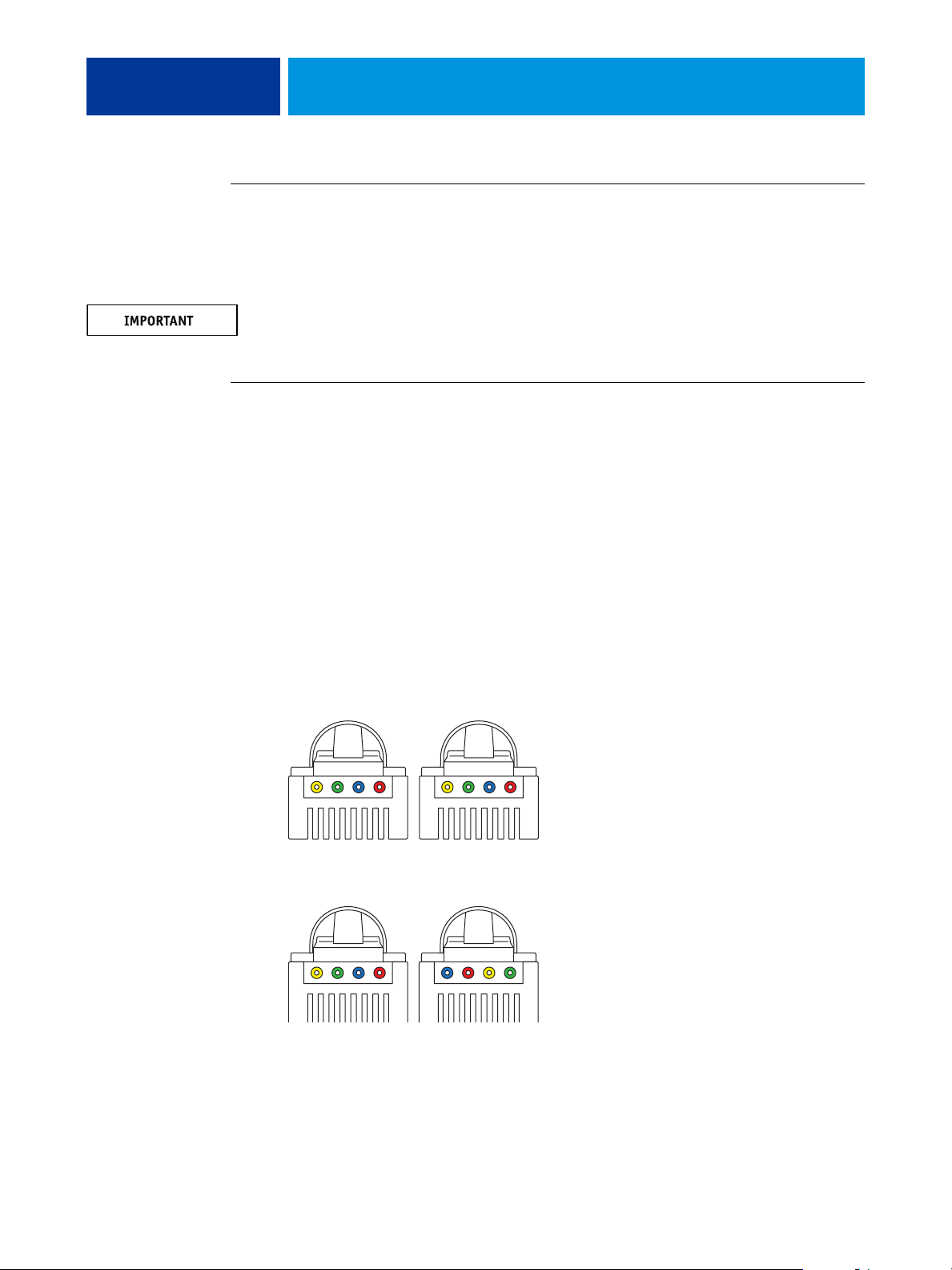
back panel. To verify the cable type, align the connectors on each end of the cable as shown in
Figure 7. On a straight-through cable, the wire arrangements are identical on both ends; on a
crossover cable, the wire arrangements are different.
Align cables side by side
and examine wires.
Straight-through cable:
wire arrangements are
identical on both connectors
1
234
1
234=
Crossover cable:
wire arrangements are different
FIGURE 7: Straight-through and crossover Ethernet cables

INSTALLATION 30
TO CONNECT TO THE NETWORK
1. Make sure that the E-41 is powered off.
2. Connect the straight-through network cable to the upper RJ-45 port on the E-41 back panel
(see Figure 6 on page 28).
Make sure that you connect the cable to the correct RJ-45 port (see Figure 6 on page 28). The
network and copier/printer interface cables look similar but are not interchangeable. The
network cable at the customer site is a straight-through Ethernet cable that connects to the
upper RJ-45 port on the E-41 back panel. The copier/printer interface cable included with
the E-41 is a 39.3 ft. Ethernet crossover cable that connects to the lower RJ-45 port on the
E-41 back panel.
The E-41 provides twisted pair connectivity to an Ethernet network. When the network cable
is connected, the Ethernet interface automatically detects the speed of the network
environment. Depending on your network speed, the following unshielded twisted pair
(UTP) network cables are supported:
•For 10BaseT, Category 3 or higher
• For 100BaseTX, Category 5 or higher (4-pair/8-wire, short-length)
• For 1000BaseT, Category 5e or higher (4-pair/8-wire, short-length)
NOTE: After power on, the network administrator should perform Network Setup, verify the
network connection, verify that the E-41 appears in the list of printers, and print a few test
documents from a networked computer that will use the E-41. For more information, see
Configuration and Setup on the User Documentation CD.
 Loading...