

Page 1

Driver Version:
1.03
Document Revision:
6
APPLICABILITY & EFFECTIVITY
Effective for all systems manufactured after January 2013
Driver Manual
(Supplement to the FieldServer Instruction Manual)
FS-8700-122
Profibus DP Master
A Sierra Monitor Company
Page 2

FS-8700-122 Profibus DP Master Manual Table of Contents
TABLE OF CONTENTS
Profibus DP Master Description ..................................................................................................................... 3 1
Driver Scope of Supply ................................................................................................................................... 3 2
2.1 Supplied by FieldServer Technologies for this driver ..................................................................................... 3
2.2 Provided by the Supplier of 3rd Party Equipment .......................................................................................... 3
2.2.1 Required 3rd Party Software ................................................................................................................... 3
2.2.2 Required 3rd Party Configuration ........................................................................................................... 3
Hardware Connections ................................................................................................................................... 4 3
3.1 Hardware Connection Tips / Hints ................................................................................................................. 4
Configuring the FieldServer as a Profibus DP Master Client ............................................................................ 5
4
4.1 FieldServer ..................................................................................................................................................... 5
4.2 Data Arrays/Descriptors ................................................................................................................................ 5
4.3 Client Side Connection Descriptors ............................................................................................................... 6
4.4 Client Side Node Descriptors ......................................................................................................................... 6
4.5 Client Side Map Descriptors........................................................................................................................... 7
4.5.1 FieldServer Related Map Descriptor Parameters ................................................................................... 7
4.5.2 Driver Related Map Descriptor Parameters ........................................................................................... 7
4.5.3 Timing Parameters ................................................................................................................................. 7
4.6 Map Descriptor Example. .............................................................................................................................. 8
4.7 Configuring the Embedded Profibus Database .............................................................................................. 9
Appendix A. Troubleshooting .............................................................................................................................. 13
Appendix A.1. Connection Tips & Hints ................................................................................................................... 13
Appendix A.1.1. An error message displays when trying to download the Profibus database............................ 13
Appendix A.1.2. Configuration Error is reported .................................................................................................. 13
FieldServer Technologies 1991 Tarob Court Milpitas, California 95035 USA Web: www.fieldserver.com
Tel: (408) 262 2299 Fax: (408) 262 2269 Toll Free: (888) 509 1970 email: support@fieldserver.com
Page 3

FS-8700-122 Profibus DP Master Manual Page 3 of 13
FieldServer Mode
Nodes
Comments
Client
DPV1 MASTER (CLASS 1)
ONLY
125
This is the maximum number of Profibus DP Slaves that can be
connected to the FieldServer. A maximum total of 1536 bytes can be
transferred with all DP Slaves.
FieldServer Technologies PART #
Description
52201
Profibus Connector
FS-8915-31
Adapter Card, Profibus Master FS-B3
Part
#
Description
Comments
HMS Anybus NetTool
for Profibus
Used to configure the Profibus network configuration and load it directly into
the Profibus card
Vendor gsd's
*.gsd files for all vendor devices to be on the network are required by HMS
NetTool for completion of network configuration.
PROFIBUS D P MASTER D E SCRIPTION
1
The FieldServer Profibus DP Master driver can be used to transfer I/O data with up to 125 Profibus DP Slave
devices. The FieldServer is programmed with an embedded database using the required 3rd party configuration
tool. The embedded database contains information on the number of slaves and I/O modules to be transferred
with each slave. The tool requires the input of GSD/E files for each slave to be connected.
Max Nodes Supported
DRIVER SC O P E OF SUPP LY 2
2.1 Sup p l ied by FieldServer Techno l o g ies for this driver
2.2 Provide d by the Supplier of 3
2.2.1 Requ ired 3
2.2.2 Requ ired 3
Connection to a correctly terminated Profibus network.
rd
Part y S o f t w are
rd
Part y C o n f i guration
rd
Part y E q u i pme nt
FieldServer Technologies 1991 Tarob Court Milpitas, California 95035 USA Web: www.fieldserver.com
Tel: (408) 262 2299 Fax: (408) 262 2269 Toll Free: (888) 509 1970 email: support@fieldserver.com
Page 4
FS-8700-122 Profibus DP Master Manual Page 4 of 13
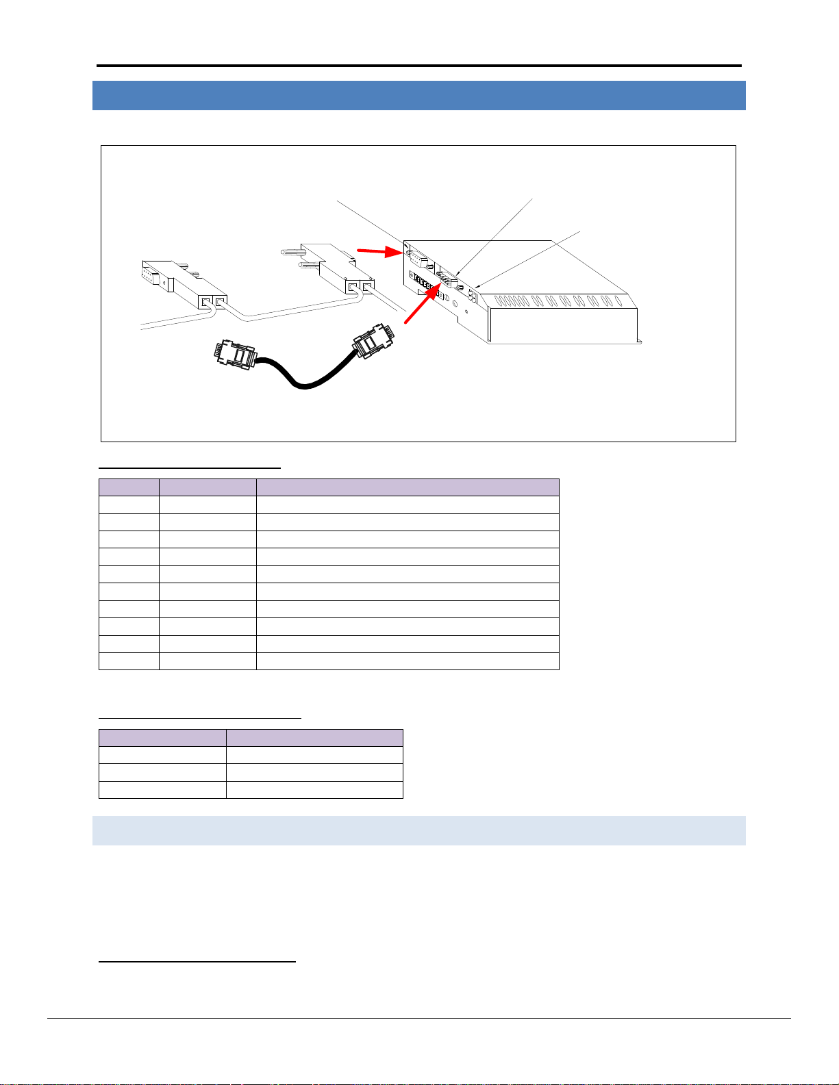
Profibus DB9 connector
NetTool RS-232 connector
Profibus Status LEDs
HMS Anybus NetTool RS-232 Serial Cable
Pin
Name
Description
Housing
Shield
Connected to PE
1
Not connected
-
2
Not connected
- 3 B-Line
Positive RxD/TxD according to RS-485 specification
4
RTS1
Request to Send
5
GND BUS2
Isolated GND from RS-485 side
6
+5V BUS2
Isolated +5V from RS-485 side
7
Not connected
- 8 A-Line
Negative RxD/TxD according to RS-485 specification
9
Not connected
-
PC Side DB9 Female
FieldServer Side DB9 Female
2 3 3 2 5
5
1
2
HARDWARE C O N N E CTIONS
3
The FieldServer is connected to the Profibus network and NetTool as shown in the connection drawing below.
Profibus DB9 Connector Pinouts
Only A-line, B-line and Shield are used for most applications.
Profibus NetTool connector Pinouts
3.1 Har d ware Connection Tips / Hin t s
Use the recommended network cable and terminators as specified by the Profibus network organization and/or
the manufacturer of the network equipment.
Used in some equipment to determine the direction of transmission.
Used for bus termination. Some devices, e.g. optical transceivers (RS-485 to fiber optics) require an external power supply from these pins.
FieldServer Technologies 1991 Tarob Court Milpitas, California 95035 USA Web: www.fieldserver.com
Tel: (408) 262 2299 Fax: (408) 262 2269 Toll Free: (888) 509 1970 email: support@fieldserver.com
Page 5

FS-8700-122 Profibus DP Master Manual Page 5 of 13
Section Title
FieldServer
Column Title
Function
Legal Values
System_Station_Address
Profibus address of the DP Master
0-125
Section Title
Data_Arrays
Column Title
Function
Legal Values
Data_Array_Name
Provide name for Data Array
Up to 15 alphanumeric characters
Data_Array_Format
Provide data format. Each Data Array can only take on
one format.
Float, Bit, UInt16, SInt16,
Packed_Bit, Byte, Packed_Byte,
Swapped_Byte
Data_Array_Length
Number of Data Objects. Must be larger than the data
storage area required by the Map Descriptors for the
data being placed in this array.
1-10,000
// Data Arrays
Data_Arrays
Data_Array_Name
,Data_Array_Format
,Data_Array_Length
Byte_Output
, Byte
, 10
Byte_Input
, Byte
, 10
Word_Output
, Uint16
, 10
Word_Input
, Uint16
, 10
Float_Output
, Float
, 10
Float_Input
, Float
, 10
CONFIGURING T H E F I EL D SERVER AS A PROFI B US DP MAST E R C L I E N T
4
For a detailed discussion on FieldServer configuration, please refer to the FieldServer Configuration Manual. The
information that follows describes how to expand upon the factory defaults provided in the configuration files
included with the FieldServer (See “.csv” sample files provided with the FieldServer).
This section documents and describes the parameters necessary for configuring the FieldServer to communicate
with up to 125 Profibus DP Slaves.
The configuration file tells the FieldServer about its interfaces, and the routing of data required. In order to enable
the FieldServer for Profibus DP Master communications, the driver independent FieldServer buffers need to be
declared in the “Data Arrays” section, the destination device addresses need to be declared in the “Client Side
Nodes” section, and the data required from the Servers needs to be mapped in the “Client Side Map Descriptors”
section. Details on how to do this can be found below.
Note that in the tables, * indicates an optional parameter, with the bold legal value being the default.
4.1 Fie l d S e rver
4.2 Data A rrays/Descriptors
Example
FieldServer Technologies 1991 Tarob Court Milpitas, California 95035 USA Web: www.fieldserver.com
Tel: (408) 262 2299 Fax: (408) 262 2269 Toll Free: (888) 509 1970 email: support@fieldserver.com
Page 6

FS-8700-122 Profibus DP Master Manual Page 6 of 13
Section Title
Connections
Column Title
Function
Legal Values
Adapter
Adapter Name
Prof_DP
// Client Side Connections
Adapters
Adapter
Prof_DP
Section Title
Nodes
Column Title
Function
Legal Values
Node_Name
Provide name for Node
Up to 32 alphanumeric
characters
Node_ID
Station address of physical remote Profibus Slave
0-125
Protocol
Specify Protocol used
Prof_Master
// Client Side Nodes
Nodes
Node_Name
, Node_ID
, Protocol
PDP_SLV003
, 3
, Prof_Master
PDP_SLV125
, 125
, Prof_Master
4.3 Cli e nt S ide Connection Descriptors
Example
4.4 Cli e nt S ide Node Descriptors
Example
FieldServer Technologies 1991 Tarob Court Milpitas, California 95035 USA Web: www.fieldserver.com
Tel: (408) 262 2299 Fax: (408) 262 2269 Toll Free: (888) 509 1970 email: support@fieldserver.com
Page 7

FS-8700-122 Profibus DP Master Manual Page 7 of 13
Column Title
Function
Legal Values
Map_Descriptor_Name
Name of this Map Descriptor
Up to 32 alphanumeric characters
Data_Array_Name
Name of Data Array where data is to be
stored in the FieldServer
One of the Data Array names from “Data
Array” section above
Data_Array_Offset
Starting location in Data Array
0 to (Data_Array_Length-1) as specified in
“Data_Array” section
Function
Function of Client Map Descriptor
Rdbc, Wrbc
Column Title
Function
Legal Values
Node_Name
Name of Node to fetch data
from
One of the node names specified in “Client Node
Descriptor” above
Profibus_Data_Type
Arrangement of buffer data
Byte, Word, Bool, Float
Address
Starting address of buffer in
bytes
0 - 243
Length
Length of Map Descriptor3
1 - 244 ( BYTE )
1 - 122 ( WORD )
1 - 1952 ( BOOL )
1 - 61 ( FLOAT )
Column Title
Function
Legal Values
Scan_Interval
Rate at which data is transferred from FieldServer data arrays to Profibus
Master buffers.
≥0.001s
3
4.5 Cli e nt S ide Map Descriptors
4.5.1 Fie l d S e rver Related Map Descri p t o r Parameters
4.5.2 Driv e r R e lated Map Descriptor Parameters
4.5.3 Tim ing P arameters
A maximum combined total length of 1536 bytes are permitted for all Map Descriptors accessing Slave devices.
FieldServer Technologies 1991 Tarob Court Milpitas, California 95035 USA Web: www.fieldserver.com
Tel: (408) 262 2299 Fax: (408) 262 2269 Toll Free: (888) 509 1970 email: support@fieldserver.com
Page 8

FS-8700-122 Profibus DP Master Manual Page 8 of 13
Map Descriptor
Map_Descriptor_Name
, Data_Array_Name
, Data_Array_Offset
, Function
, Node_Name
, Profibus_Data_Type
, Address
, Length
, Scan_Interval
Word_In_003
, Word_Input
, 0
, Rdbc
, PDP_SLV003
, Word
, 0
, 50
, 1s
Word_Out_003
, Word_Output
, 0
, Wrbc
, PDP_SLV003
, Word
, 0
, 50
, 1s
Byte_In_125
, Byte_Input
, 0
, Rdbc
, PDP_SLV125
, Byte
, 0
, 120
, 1s
Byte_Out_125
, Byte_Output
, 0.
, Wrbc
, PDP_SLV125
, Byte
, 0
, 120
, 1s
Map Descriptor
Map_Descriptor_Name
, Data_Array_Name
, Data_Array_Offset
, Function
, Node_Name
, Profibus_Data_Type
, Address
, Length
, Scan_Interval
Word_In
, Word_Input
, 0
, Rdbc
, PDP_SLV003
, Word
, 0
, 50
, 1s
Byte_In
, Byte_Input
, 0
, Rdbc
, PDP_SLV003
, Byte
, 0
, 120
, 1s
Map Descriptor
Map_Descriptor_Name
, Data_Array_Name
, Data_Array_Offset
, Function
, Node_Name
, Profibus_Data_Type
, Address
, Length
, Scan_Interval
Word_Out
, Word_Out
, 0
, Wrbc
, PDP_SLV003
, Word
, 0
, 50
, 1s
Byte_Out
, Byte_Out
, 0
, Wrbc
, PDP_SLV003
, Byte
, 0
, 120
, 1s
Map Descriptor
Map_Descriptor_Name
, Data_Array_Name
, Data_Array_Offset
, Function
, Node_Name
, Profibus_Data_Type
, Address
, Length
, Scan_Interval
Word_In
, Word_Input
, 0
, Rdbc
, PDP_SLV003
, Word
, 0
, 50
, 1s
Word_Out
, Word_Output
, 0
, Wrbc
, PDP_SLV003
, Word
, 0
, 50
, 1s
Byte_In
, Byte_Input
, 0
, Rdbc
, PDP_SLV003
, Byte
, 0
, 120
, 1s
Byte_Out
, Byte_Output
, 0
, Wrbc
, PDP_SLV003
, Byte
, 0
, 120
, 1s
4.6 Map D e s c r iptor Example
This example demonstrates the transfer of I/O data with Remote Profibus DP Slaves using Station Addresses of 1 and 125.
4.6.1 Exampl e if t he device only has an In pu t bu f fe r
4.6.2 Exampl e if the device only has an Outp ut b uf f e r
4.6.3 Example i f the device has both an Input and a n Ou t p u t buffer
FieldServer Technologies 1991 Tarob Court Milpitas, California 95035 USA Web: www.fieldserver.com
Tel: (408) 262 2299 Fax: (408) 262 2269 Toll Free: (888) 509 1970 email: support@fieldserver.com
Page 9
FS-8700-122 Profibus DP Master Manual Page 9 of 13
Module
Map Descriptor Function
In
Rdbc
Out
Wrbc
In/Out
Wrbc/Rdbc4
4
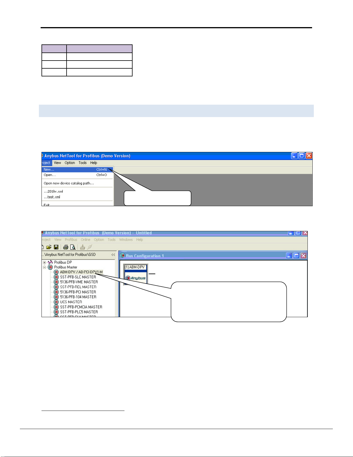
Select Project-> New
Expand the Profibus Master Tree, select the
ABM-DPV device and drag it onto the Bus
Configuration Screen. This is the X30
The table below shows the map descriptor function that should be used in the config.csv with a specific module.
A Profibus Slave device will have one of three types of I/O Modules, Input, Output or Input/Output. The I/O
Module type can only be found by analyzing the GDS file of the device in a Profibus Software system.
4.7 Conf i gu ring the Embedded Profi b u s D atabase
The Profibus Master has to be configured with an embedded database that contains information about the
Profibus Network data rate and remote Slave devices to access. The HMS Anybus NetTool for Profibus software
must be installed and used for this purpose. Connect a serial RS-232 cable from the PC with the tool installed to
the serial connector on the X30 as shown in Section 3:
Expand the Profibus Master Tree, select the ABM-DPV device and drag it onto the Bus Configuration Screen. This is
the FieldServer Profibus DP Master device.
FieldServer Profibus DP Master device.
2 Map Descriptors need to be configured, one for the input module and one for the output
FieldServer Technologies 1991 Tarob Court Milpitas, California 95035 USA Web: www.fieldserver.com
Tel: (408) 262 2299 Fax: (408) 262 2269 Toll Free: (888) 509 1970 email: support@fieldserver.com
Page 10

FS-8700-122 Profibus DP Master Manual Page 10 of 13
Expand the Profibus DP tree and drag the
Slave Device you want to connect to onto
the Bus Configuration window. The
ANYBUS-S PDP Slave device is shown here
for illustration purposes
If your device is not listed, import the
device’s GSD file by right clicking on
Profibus DP and selecting “Install new GS*
file”.
Right-click on the Profibus Slave and assign its Profibus address.
Continue adding all other Slaves and setting their Profibus addresses.
Right click on the ABM-DPV Master device and select Object Properties. Set the Master Station Address to the
same as the System_Station_Address used in the FieldServer’s config.csv file. Also set the desired Profibus
Network Baud rate.
FieldServer Technologies 1991 Tarob Court Milpitas, California 95035 USA Web: www.fieldserver.com
Tel: (408) 262 2299 Fax: (408) 262 2269 Toll Free: (888) 509 1970 email: support@fieldserver.com
Page 11

FS-8700-122 Profibus DP Master Manual Page 11 of 13
Select the first slave device, right-click on the Slot 1 line and choose Module selection. Now add I/O modules up to
the total number of bytes or words that will be transferred with this Slave as set up in the config.csv file. For
Example, for the Map Descriptor for Slave1 using 50 Words In and Out, you would choose the following modules:
Continue selecting other Slaves and adding modules for them as well.
Important Note: Changing of Input and Output Addresses are not allowed. All addresses must be contiguous for
the Profibus to work correctly.
Select Online-> Driver selection and on the serial Tab, choose the serial port on the PC connected to the X30 by
clicking on Configure-> Configure path.
FieldServer Technologies 1991 Tarob Court Milpitas, California 95035 USA Web: www.fieldserver.com
Tel: (408) 262 2299 Fax: (408) 262 2269 Toll Free: (888) 509 1970 email: support@fieldserver.com
Page 12

FS-8700-122 Profibus DP Master Manual Page 12 of 13
Ensure that the X30 FieldServer is running and that a matching configuration file with Node and Map Descriptors
for each slave configured has been downloaded to the X-30.
Make sure you can connect with Ruinet to the X30 and there are no configuration errors.
Choose Online-> Download configuration to install the embedded database in the X30.
Important Note:
Note that the X30 must be running with a valid configuration file before it will allow download of a new database.
FieldServer Technologies 1991 Tarob Court Milpitas, California 95035 USA Web: www.fieldserver.com
Tel: (408) 262 2299 Fax: (408) 262 2269 Toll Free: (888) 509 1970 email: support@fieldserver.com
Page 13

FS-8700-122 Profibus DP Master Manual Page 13 of 13
Appendix A. TROUBLESHOOTING
Appendix A.1. Connection Tips & Hints
Appendix A.1.1. An error message displays when trying to download the Profibus database
Ensure that the correct serial port has been selected in the configure path setting.
Ensure that the X30 is powered up with a valid configuration file declaring all the Slaves to be communicated
with.
Confirm that the Run Led is flashing.
The following message on the E screen of Ruinet is shown when the X30 detects a request for new database
download:
Detected New Profibus Database!
Restarting FieldServer in 10 seconds...
Appendix A.1.2. Configuration Error is reported
Ensure that the correct Map Descriptor function has been used. Refer to Sections 4.5.2 and 0
Ensure that the number of configured bytes on the card has not been exceeded. A maximum of 1536 bytes
can be accessed.
FieldServer Technologies 1991 Tarob Court Milpitas, California 95035 USA Web: www.fieldserver.com
Tel: (408) 262 2299 Fax: (408) 262 2269 Toll Free: (888) 509 1970 email: support@fieldserver.com
 Loading...