

Page 1

APPLICABILITY & EFFECTIVITY
Effective for all systems manufactured after March 2009
FieldServer X-25 Start-Up Guide
Kernel Version:
5.12
Document Revision:
2
Sierra Monitor Company
Page 2

FieldServer FS-X25 Start-Up Guide Table of Contents
TABLE OF CONTENTS
1 Equipment Set-Up .......................................................................................................................................... 3
1.1 Supplied equipment....................................................................................................................................... 3
1.2 Mounting ....................................................................................................................................................... 3
1.3 Wiring ............................................................................................................................................................ 3
1.3.1 Compliance with UL Regulations ........................................................................................................... 3
1.4 Specifications ................................................................................................................................................. 4
2 Product Description ....................................................................................................................................... 5
2.1 Features ......................................................................................................................................................... 5
2.2 LED Indicators ................................................................................................................................................ 5
3 Connection to the Device ............................................................................................................................... 6
3.1 Serial Connection ........................................................................................................................................... 6
3.1.1 DB-9 Pinouts for RS-232 Connection ...................................................................................................... 6
3.1.2 DB-9 Pinouts for RS-485 Connection ...................................................................................................... 7
3.2 Ethernet Connection ...................................................................................................................................... 7
4 Operation ....................................................................................................................................................... 8
4.1 Record Identification Data ............................................................................................................................. 8
4.2 Power up the device ...................................................................................................................................... 8
4.3 Install and Run the Utility Software ............................................................................................................... 8
4.4 Connect the PC to the FieldServer over the Ethernet port. ........................................................................... 8
4.5 Identification of the FieldServer on the Network .......................................................................................... 8
4.6 Connection to the FieldServer Using RUI (Ruinet) ......................................................................................... 9
4.7 Upload the Default Configuration ................................................................................................................. 9
4.8 Change the Configuration File to Meet the Application ................................................................................ 9
4.9 Download the updated Configuration file ..................................................................................................... 9
4.10 Test and Commission the FieldServer .......................................................................................................... 10
Appendix A. Troubleshooting Tips ....................................................................................................................... 11
Appendix A.1. Connection to the FieldServer .......................................................................................................... 11
Appendix A.2. Technical support ............................................................................................................................. 11
Appendix A.3. Material Service Orders (MSO) Procedure ....................................................................................... 11
Appendix B. Limited Warranty ............................................................................................................................. 12
FieldServer Technologies 1991 Tarob Court Milpitas, California 95035 USA Web: www.fieldserver.com
Tel: (408) 262 2299 Fax: (408) 262 2269 Toll Free: (888) 509 1970 email: support@fieldserver.com
Page 3

FieldServer FS-X25 Start-Up Guide Page 3 of 12
1 EQUIPMENT SET-UP
1.1 Supplied equipm ent
FS-X25 Series FieldServer.
loaded with Modbus RTU driver, SMT Ethernet driver and any other drivers ordered. A default
configuration file has already been loaded onto the FieldServer. Check the Driver Manual and the
FieldServer Configuration Manual for further information on this file.
USB Flash Drive loaded with:
FS-X25 Series Start-up Guide
FieldServer Configuration Manual
FieldServer Utilities Manual
All FieldServer Driver Manuals
Support Utilities
Any additional folders related to special files configured for a specific FieldServer
Additional components as required - See Driver Manual Supplement for details
Accessories:
7-ft Cat5 cable with RJ45 connectors at both ends (Part # FS-8915-10)
Power Supply
1.2 Mounting
The FS-X25 Series FieldServer is supplied with an accessory bag which allows selection of adhesive feet (for
standing on a shelf) or mounting plates for wall or panel mount. A DIN Rail Mounting Kit (P/N FS-8915-28) may be
ordered separately.
1.3 Wiring
5-30VDC must be connected to the terminal block
1.3.1 Compliance with UL Regulatio ns
For UL compliance, the following instructions must be met when operating the FieldServer.
The units shall be powered by listed LPS or Class 2 power supply suited to the expected operating temperature
range.
The interconnecting power connector and power cable shall:
Comply with local electrical code.
Be suited to the expected operating temperature range.
Meet the current and voltage rating for the FieldServer/Net
Furthermore, the interconnecting power cable shall:
Be of length not exceeding 3.05m (118.3”)
Be constructed of materials rated VW-1 or FT-1 or better.
If the unit is to be installed in an operating environment with a temperature above 65 °C, it should be installed
in a Restricted Access Area requiring a key or a special tool to gain access
This device must not be connected to a LAN segment with outdoor wiring.
FieldServer Technologies 1991 Tarob Court Milpitas, California 95035 USA Web: www.fieldserver.com
Tel: (408) 262 2299 Fax: (408) 262 2269 Toll Free: (888) 509 1970 email: support@fieldserver.com
Page 4

FieldServer FS-X25 Start-Up Guide Page 4 of 12
Power requirements
Multi-mode power adapter, 5V - 30V DC, 500 mA
Optional: 110V/230V switchable power supply
Physical Dimensions
(LxWxD):
4.55 x 4.50 x 1.35 in. (11.56 x 11.68 x 3.43 cm)
Weight:
0.4 lb (0.18 Kg)
Field Connections
Ethernet Port
10BaseT, 100BaseTX RJ45 (auto-sensing)
Serial Port
RS-232/RS-422/RS-485 switchable
Up to 115K baud
DB9 connector
Drivers
Drivers available for a wide range of Ethernet and serial protocols – check driver information sheet
Environment:
Operating Temperature:
-40-85°C (-40 – 185°F)
Humidity:
10 - 95% RH (non-condensing)
Approvals:
UL
FCC Class A, Part 15
CE EN55022, EN 55024
(Specifications subject to change without notice)
1.4 Specifications
FieldServer Technologies 1991 Tarob Court Milpitas, California 95035 USA Web: www.fieldserver.com
Tel: (408) 262 2299 Fax: (408) 262 2269 Toll Free: (888) 509 1970 email: support@fieldserver.com
Page 5

FieldServer FS-X25 Start-Up Guide Page 5 of 12
Ethernet connection – Tx/Rx communication activity
Green LED – 10/100 indicator
LED on: 100 megabit connection
LED off: 10 megabit connection
Orange LED – Link activity indicator
LED on: Link active
LED off: Link inactive
Serial connection – CPU communication activity
Serial 1, Serial 2
Flashes to indicate communication
activity on the associated serial
port
CPU communication activity
Flashes once a second to indicate
normal operation.
2 PRODUCT DESCRIPTION
2.1 Features
Two DB-9 serial ports (defaulted to RS-485 unless specified differently at the time of purchase).
Data communications speeds of 300 to 115200 baud supported.
10/100BaseT Ethernet LAN interface (auto-sensing)
Easy configuration via text editor or spreadsheet and the available utilities.
OPC server available
Configuration utility
Diagnostic utility
System integration services available
2.2 LED Indicators
FieldServer Technologies 1991 Tarob Court Milpitas, California 95035 USA Web: www.fieldserver.com
Tel: (408) 262 2299 Fax: (408) 262 2269 Toll Free: (888) 509 1970 email: support@fieldserver.com
Page 6

FieldServer FS-X25 Start-Up Guide Page 6 of 12
Typical null modem connection. (Used when
Hardware RTS→CTS flow control is required).
“3 wire” null modem connection (Used when Hardware
RTS→CTS flow control is not required).
1 9 5
6
3 CONNECTION TO THE DEVICE
3.1 Serial Connectio n
A DB-9 cable should be connected between the Serial port on the FS-X25 and the serial port of the target serial
device.
The Serial 1 port can be configured as either P1 (for RS-232 connection) or R1 (for RS-485 connection). Likewise
the Serial 2 port can be configured as P2 or R2. Note that if a P1 and a R1 connection is declared, the one declared
second will cause a configuration error on the error screen.
Figure 1: Serial Connection Ports
3.1.1 DB-9 Pinouts for RS -232 Connect io n
Used to connect to DTE type devices.
The cable used (serial cross-over cable) is available at any electronics retailer/distributor.
FieldServer Technologies 1991 Tarob Court Milpitas, California 95035 USA Web: www.fieldserver.com
Tel: (408) 262 2299 Fax: (408) 262 2269 Toll Free: (888) 509 1970 email: support@fieldserver.com
Page 7

FieldServer FS-X25 Start-Up Guide Page 7 of 12
Four Wire (full duplex multidrop)
Two Wire (1/2 duplex)
3.1.2 DB-9 Pinouts for RS -485 Connect io n
Note: The flow signals, RTS and CTS, should be connected as per diagram when unused to prevent loss of
performance on the FieldServer.
For users who do not wish to construct their own connector, we recommend using a DB-9 to screw block
connector which can be purchased from L-Com, Inc.
Item #: DGB9FT Ph: 1-800-341-5266 http://www.l-com.com/item.aspx?id=8141
3.2 Ethernet Connect io n
The FS-X25 Ethernet port automatically senses an uplink connection, and may therefore be connected to a PC or a
hub/switch using either a crossover cable (not supplied) or a direct Ethernet cable (supplied).
Figure 2: Ethernet Connection port
FieldServer Technologies 1991 Tarob Court Milpitas, California 95035 USA Web: www.fieldserver.com
Tel: (408) 262 2299 Fax: (408) 262 2269 Toll Free: (888) 509 1970 email: support@fieldserver.com
Page 8
FieldServer FS-X25 Start-Up Guide Page 8 of 12
4 OPERATION
4.1 Record Identif icatio n Data
Each FS-x25 has a unique serial number and MAC address located on the underside of the unit. These numbers
should be recorded as they may be required for technical support.
Serial Number: __________________________________________________
MAC Address: __________________________________________________
4.2 Power up the device
Apply power to the device. Ensure that the power supply used complies with the specifications provided in
Section 1.3
4.3 Install and Run the Utility Software
Plug the supplied USB flash drive into the USB port on a PC/laptop. Open Index.html to get the menu of
options, run the Install option and follow the installation instructions.
Once installed, the FieldServer Utilities can be located in the Windows Start menu and as a desktop icon.
4.4 Connect the PC to the FieldServer o ver the Ethernet port.
Use the supplied Cat5 UTP Ethernet cable to connect between the N1 port of the FieldServer and the hub.
Refer to Section 3.2 for more information.
Disable any wireless Ethernet adapters on the PC/Laptop,
It is important that the PC/Laptop is on the same subnet as the FieldServer. The FS-x25 does not have a
default IP address, but it will be 192.168.2.xxx. Refer to the FieldServer Utilities Manual for information on
how to change the FieldServer’s IP address.
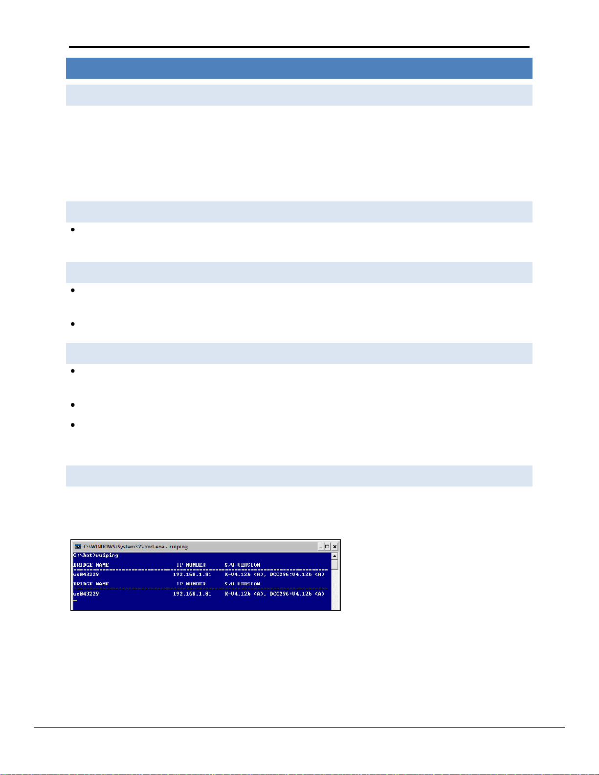
4.5 Identification of the FieldServer on the Netwo rk
Select Start|Programs|FieldServer Utilities; double click on the Ruiping Utility. The display should show
FieldServer Name IP Number (192.168.2.X) FieldServerVersion
If necessary, refer to Appendix A for troubleshooting tips.
FieldServer Technologies 1991 Tarob Court Milpitas, California 95035 USA Web: www.fieldserver.com
Tel: (408) 262 2299 Fax: (408) 262 2269 Toll Free: (888) 509 1970 email: support@fieldserver.com
Page 9

FieldServer FS-X25 Start-Up Guide Page 9 of 12
4.6 Connection to t he FieldServ er Using RUI ( Ruinet)
Select Start|Programs|FieldServer Utilities, double click on the Remote User Interface icon or double click on the
Remote User Interface Icon on the desktop.
If Ruinet does not automatically bring you to the main menu, select the FieldServer by typing the 2-digit number to
the left of the title name.
If necessary, refer to Appendix A for troubleshooting tips.
4.7 Upload the De fault Configuratio n
The configuration of the FieldServer is provided to the FieldServer’s operating system via a comma-delimited file
called “CONFIG.CSV”. If ordered with the FieldServer, the custom configuration is installed; (Reference
documentation FS-8790-XX). If a custom configuration is not purchased, a template config.csv is shipped on the
FieldServer. Refer to the Configuration Manual and the Driver Manual(s) provided with the FieldServer for further
information on configuration files.
In the main menu of the Remote User Interface screen, type “U” to upload the configuration. Then type “U” again.
The Remote User Interface Utility will fetch the default configuration and put it into the Configuration File folder
(Start|Programs|FieldServerUtilities|Configuration File folder).
4.8 Change the C onfiguratio n File to M eet the Applicat io n
Refer to the Configuration Manual in conjunction with the Driver supplements for information on configuring the
FieldServer. FieldServer Technologies offers training on this topic as well as a configuration service to complete
this portion of the work. See www.fieldserver.com for specific details.
4.9 Download the updat ed Configurat io n file
Before attempting to send files to the FieldServer, ensure that the files are in the configuration file folder.
Refer to the FieldServer Utilities manual for further information.
From the main menu, type "D" to access the “download” menu,
FieldServer Technologies 1991 Tarob Court Milpitas, California 95035 USA Web: www.fieldserver.com
Tel: (408) 262 2299 Fax: (408) 262 2269 Toll Free: (888) 509 1970 email: support@fieldserver.com
Page 10

FieldServer FS-X25 Start-Up Guide Page 10 of 12
Type "L" (for local filename) to specify the name and extension of the file to be sent to the FieldServer. Hit
<Enter> when done.
The Remote User Interface Utility will automatically select config.csv for download of csv files. On rare
occasions where other files need to be downloaded to the FieldServer type “O” for other files, then type “R”
to specify the remote filename needed on the FieldServer.
When satisfied that the correct file names are specified, Type "D" to download the file to the FieldServer. The
Remote User Interface Utility will display a menu showing download progress.
Note: the Remote User Interface Utility will indicate when download is complete. DO NOT reset the
FieldServer before this message displays, as this could corrupt the FieldServer.
Once download is complete, hit <Esc> to get back to the main menu and use the "!" option (or simply cycle
power to the FieldServer) to put the new file into operation. Note that it is possible to do multiple downloads
to the FieldServer before resetting it.
Firmware created by FieldServer Technologies can be downloaded from the configuration file by simply typing
“F” from the download menu. Note that FieldServer usually supplies firmware upgrades as an install.zip, for
which a separate procedure is used, (See ENote 037 on the USB flash drive in a folder called Library).
4.10 Test and Co mmission t he FieldServer
Connect the FieldServer to the third party device(s), and test the application.
From the main menu of Ruinet, type “O” to see the number of messages on each protocol.
In case of problems, refer to Appendix A or the Troubleshooting Guide which can be found in the FieldServer
Utilities directory under Documentation
FieldServer Technologies 1991 Tarob Court Milpitas, California 95035 USA Web: www.fieldserver.com
Tel: (408) 262 2299 Fax: (408) 262 2269 Toll Free: (888) 509 1970 email: support@fieldserver.com
Page 11

FieldServer FS-X25 Start-Up Guide Page 11 of 12
Appendix A. Troubleshooting Tips
Appendix A.1. Connection to the FieldServer
Confirm that the network cabling is correct.
Confirm that the computer network card is operational and correctly configured.
Confirm that there is an Ethernet adapter installed in the PC’s Device Manager List,, and that it is configured to
run the TCP/IP protocol.
Check the Ethernet OK LED
Check the “Activity” LED on the Ethernet connection - this should flash at least once every 2 seconds if RUI is
still running.
Check that the netmask is correct.
Go to Start|Run
Type in “ipconfig”
The account settings should be displayed.
Ensure that the IP address is 192.168.2.xxx and the netmask 255.255.255.0
Ensure that the PC and FieldServer are on the same IP Network, or assign a Static IP Address to the PC on the
192.168.2.0 network using the Remote User Interface Utility. Refer to the FieldServer Utilities manual for
information.
If using Windows XP, ensure that the firewall is disabled.
Ensure that all other Ethernet cards active on the PC, especially wireless adapters are disabled.
Refer to the FieldServer Troubleshooting Guide which can be found in the FieldServer Utilities directory under
Documentation
Appendix A.2. Technical support
Before contacting Technical support to report an issue, go to Start|Programs|FieldServer utilities|Tools and run
the FST_Diag program. Take a log (See ENote0058 in the folder called Library on the USB Flash Drive). Send this
log together with the configuration file to support@fieldserver.com for evaluation.
Note that while all necessary documentation is shipped with the FieldServer on the USB flash drive, these
documents are constantly being updated. Newer versions may be available on the web at www.fieldserver.com
Appendix A.3. Material Service Orders (MSO) Procedure
A FieldServer Sales Customer Representative can be contacted at 408-262-2299 x104 if a manufacturing defect is
suspected. The serial number and reason for return of the product will be requested, and a MSO number will be
supplied should the circumstances warrant a return.
Note: 1. Please pack the item for repair securely and ship it prepaid and insured. FieldServer Technologies is not
responsible for any damages caused to the product due to shipping.
Note 2. FieldServer Technologies will not accept items for repair without an MSO number.
FieldServer Technologies 1991 Tarob Court Milpitas, California 95035 USA Web: www.fieldserver.com
Tel: (408) 262 2299 Fax: (408) 262 2269 Toll Free: (888) 509 1970 email: support@fieldserver.com
Page 12

FieldServer FS-X25 Start-Up Guide Page 12 of 12
Appendix B. Limited Warranty
FieldServer Technologies warrants its products to be free from defects in workmanship or material under normal
use and service for two years after date of shipment. FieldServer Technologies will repair or replace without
charge any equipment found to be defective during the warranty period. Final determination of the nature and
responsibility for defective or damaged equipment will be made by FieldServer Technologies personnel.
All warranties hereunder are contingent upon proper use in the application for which the product was intended
and do not cover products which have been modified or repaired without FieldServer Technologies approval or
which have been subjected to accident, improper maintenance, installation or application, or on which original
identification marks have been removed or altered. This Limited Warranty also will not apply to interconnecting
cables or wires, consumables or to any damage resulting from battery leakage.
In all cases FieldServer Technology’s responsibility and liability under this warranty shall be limited to the cost of
the equipment. The purchaser must obtain shipping instructions for the prepaid return of any item under this
warranty provision and compliance with such instruction shall be a condition of this warranty.
Except for the express warranty stated above, FieldServer Technologies disclaims all warranties with regard to the
products sold hereunder including all implied warranties of merchantability and fitness and the express warranties
stated herein are in lieu of all obligations or liabilities on the part of FieldServer Technologies for damages
including, but not limited to, consequential damages arising out of/or in connection with the use or performance
of the product.
FieldServer Technologies 1991 Tarob Court Milpitas, California 95035 USA Web: www.fieldserver.com
Tel: (408) 262 2299 Fax: (408) 262 2269 Toll Free: (888) 509 1970 email: support@fieldserver.com
 Loading...