

Page 1

FieldServer Technologies
A Sierra Monitor Corporation Company
1991 Tarob Court, Milpitas, California 95035 USA
Phone: (408) 262-2299
Toll Free: (888) 509-1970
Fax: (408) 262-9042
Email: support@fieldserver.com
Web Site: www.fieldserver.com
SlotServer LonWorks Open Interface
APPLICABILITY & EFFECTIVITY
This manual provides instructions for the following FieldServer products:
Description
FS-RA-CLX-LON-000
The instructions are effective for the above as of January 2006
Instruction Manual Part Number: T17010
Applicability and Effectivity
Rev. A2.
Page 2

FS-RA-CLX-LON-000_SlotServer_LonWorks_Open_Interface_(T17010) Table of Contents
TABLE OF CONTENTS
1.
INTRODUCTION............................................................................................................. 3
1.1.
About this product ...................................................................................................... 3
1.2.
About LonWorks and Profiling.................................................................................... 3
1.3.
Connection Capability ................................................................................................ 3
2.
PRE-STARTUP CHECKLIST.......................................................................................... 4
2.1.
Accessories supplied with the SlotServer................................................................... 4
2.2.
Third party components (not supplied by FieldServer Technologies) ......................... 4
2.3.
Required configuration for the SlotServer................................................................... 4
3.
SLOTSERVER TOPOLOGY........................................................................................... 5
3.1.
Hardware Connection Tips / Hints.............................................................................. 5
4.
SLOTSERVER INSTALLATION ..................................................................................... 6
4.1.
SlotServer Ports and Displays.................................................................................... 6
4.2.
Inside Cover Door Label ............................................................................................ 7
4.3.
Technical Specifications............................................................................................. 8
5.
SLOTSERVER COMMUNICATIONS QUICK START EXAMPLE PROJECT ................. 9
5.1.
Step 1: Create or use an existing RSLogix project ..................................................... 9
5.2.
Step 2: Add and configure the SlotServer as an IO Module ......................................10
5.3.
Step 3: Write Ladder Program to Get LonWorks Input Data......................................11
5.4.
Step 4: Write Ladder Program to Send LonWorks Output Data.................................14
5.5.
Step 5: Download the RSLogix Program and Run.....................................................14
5.6.
Step 6: Bind LonWorks Variables..............................................................................14
5.7.
Step 7: Interpret the Network Variable Data..............................................................14
6.
ACCESSING ALL LONWORKS FUNCTION BLOCK DATA.........................................18
6.1.
Input Data from Function Blocks In[1] to In[24]..........................................................18
6.2.
Output Data from Function Blocks Out[1] to Out[24] .................................................18
6.3.
Optimizing performance for smaller applications.......................................................19
APPENDIX A. ADVANCED TOPICS.....................................................................................21
Appendix A.1. Using the FieldServer RUI for Troubleshooting. ...........................................21
Appendix A.2. Installing SlotServer on a Remote Rack using CNB cards ...........................21
Appendix A.2.1. Hardware and Software requirements....................................................21
Appendix A.2.2. Setup .....................................................................................................21
Appendix A.2.3. RSLogix configuration............................................................................22
Appendix A.2.4. RSNetWorx configuration ......................................................................22
Appendix A.2.5. Testing...................................................................................................23
APPENDIX B. TROUBLESHOOTING TIPS ..........................................................................24
Appendix B.1. Things to check when communications has failed........................................24
APPENDIX C. USING LONMAKER TO COMMISSION A SLOTSERVER ............................25
APPENDIX D. NETWORK VARIABLES LIST – LONWORKS OPEN INTERFACE PROFILE
26
Appendix D.1. LonWorks Network Variables Summary.......................................................26
FieldServer Technologies 1991 Tarob Court Milpitas, California 95035 USA Web:www.fieldServer.com
Tel: (408) 262-2299 Fax: (408) 262-2296 Toll_Free: 888-509-1970 email: support@fieldServer.com
Page 3

FS-RA-CLX-LON-000_SlotServer_LonWorks_Open_Interface_(T17010) Page 3 of 28
1. Introduction
1.1. About this product
The SlotServer Instruction Manual provides the information necessary to configure the
SlotServer, allowing an Allen Bradley ControlLogix platform to pass data between a
ControlLogix CPU and other third party communications protocols supported by the
SlotServer. The SlotServer uses implicit communications between the CPU and the
SlotServer and is consequently treated as an I/O Server in RSLogix.
The SlotServer Instruction Manual covers information for installing the SlotServer, and
configuring the module to transfer data with the CPU on the ControlLogix Rack. Depending
on the SlotServer Module ordered, supplementary driver manuals are provided for
information on how to configure the third party protocols residing in the SlotServer.
1.2. About LonWorks and Profiling
Inherent to the design of LonWorks is the intention that all nodes residing on a LonWorks
network possess a profile which accurately describes the network variables available to the
LonWorks network. This profile is declared to the LonWorks network by means of an
External Interface File (XIF). This XIF remains unchanged for any particular profile. In other
words, a change in the XIF is by definition a new profile.
The Open Interface profile for SlotServer provides a generic list of SNVT’s that can be used
to bind the most common LonWorks data types to the SlotServer for data transfer. This
document describes the fixed Open Interface profile for the SlotServer. However, as a
LonMark compatible product, the SlotServer platform is also capable of supporting other
profiles. For further information, please contact FieldServer Technologies and enquire
about available Specific Profiles and other SlotServer Profiling Services.
1.3. Connection Capability
SLOTSERVER MODE
CLIENT (SCANNER) 15
SERVER (ADAPTER) N/A
FieldServer Technologies 1991 Tarob Court Milpitas, California 95035 USA Web:www.fieldServer.com
Tel: (408) 262-2299 Fax: (408) 262-2296 Toll_Free: 888-509-1970 email: support@fieldServer.com
LONWORKS
NODES
COMMENTS
As an implicitly bound object in LonWorks, the
LonWorks protocol only supports the binding of this
device to no more than 15 other nodes.
The ControlLogix CPU is always configured as a
scanner to communicate with the SlotServer adapter.
Page 4

FS-RA-CLX-LON-000_SlotServer_LonWorks_Open_Interface_(T17010) Page 4 of 28
2. Pre-Startup checklist
2.1. Accessories supplied with the SlotServer
Please verify that the following components were supplied with the SlotServer module:
FieldServer Technologies
PART #
Description
2-way combi-comb connector for LonWorks port
Software CD
CAT-5 Direct Ethernet Cable
Documentation Binder
2.2. Third party components (not supplied by FieldServer Technologies)
The following components will need to be procured as a minimum for achieving a
LonWorks/ControlLogix integration. Ensure that these are available before commencing
with commissioning
Part # Description
AB1756-Ax ControlLogix Rack
AB1756-L55/L61 ControlLogix CPU
AB1756-PA7x ControlLogix PSU
9324-RLD300ENE RSLOGIX 5000
LonWorks NetWork Manager (e.g: LonMaker)
LonWorks Network components.
2.3. Required configuration for the SlotServer
In order to achieve data transfer between CPU tags and LonWorks network variables, the
SlotServer will need to be commissioned into a LonWorks network using a LonWorks
Network Manager. Once commissioned and bound, data from the LonWorks network is
accessed by I/O image transfer in the ControlLogix CPU.
FieldServer Technologies 1991 Tarob Court Milpitas, California 95035 USA Web:www.fieldServer.com
Tel: (408) 262-2299 Fax: (408) 262-2296 Toll_Free: 888-509-1970 email: support@fieldServer.com
Page 5

FS-RA-CLX-LON-000_SlotServer_LonWorks_Open_Interface_(T17010) Page 5 of 28
3. SlotServer Topology
The diagram below shows a typical implementation of the SlotServer LonWorks Open Interface
Module
3.1. Hardware Connection Tips / Hints
• Note that the LonWorks TP/FT-10 medium is polarity insensitive and therefore does not
require attention to connection orientation on the pins.
• Follow the Rockwell documentation for guidelines on inserting the SlotServer module
into the ControlLogix backplane / rack.
FieldServer Technologies 1991 Tarob Court Milpitas, California 95035 USA Web:www.fieldServer.com
Tel: (408) 262-2299 Fax: (408) 262-2296 Toll_Free: 888-509-1970 email: support@fieldServer.com
Page 6

FS-RA-CLX-LON-000_SlotServer_LonWorks_Open_Interface_(T17010) Page 6 of 28
status
4. SlotServer Installation
The SlotServer plugs directly into the AB1756 ControlLogix rack. Take note of the slot number
used for the SlotServer as this will be needed when configuring the I/O in the RSLogix software.
4.1. SlotServer Ports and Displays
Note that there are several hardware ports available on the SlotServer card, but that this
SlotServer model only makes use of a select few. The ports and displays of interest are as
shown in the diagram below:
Scrolling display shows card messages
Card Status Indicators show general card
Service Pin For LonWorks Commissioning
Communications Status LED’s show status of
communications and card software.
TP/FT10 LonWorks Connection
Trade Port. Used for advanced troubleshooting
only. See Appendix A.
Not Used. Do not connect anything here.
Scrolling Display
This will Display an OK status when the SlotServer has powered up successfully.
Card Status Indicators:
The Comm and OK lights will indicate green when the SlotServer has powered up
successfully. The Sys indicator will indicate green if the Lon Nodes are all communicating,
and red otherwise.
Service Pin
To be used for commissioning the SlotServer into a LonWorks network
FieldServer Technologies 1991 Tarob Court Milpitas, California 95035 USA Web:www.fieldServer.com
Tel: (408) 262-2299 Fax: (408) 262-2296 Toll_Free: 888-509-1970 email: support@fieldServer.com
Page 7

FS-RA-CLX-LON-000_SlotServer_LonWorks_Open_Interface_(T17010) Page 7 of 28
Communications Status LED’s
LED Description
When the SlotServer is powered up, this light will start flashing after approximately 2
Run
LonSvc
NodeOff
Conf
Err
Sys Err
Com Err
minutes. If this light does not flash, it is an indication that the firmware is not running,
and that the SlotServer will not be operating.
This light will flash when the card’s Neuron chip is unconfigured, and will extinguish
when the SlotServer has been commissioned into a Network.
This light indicates that a device bound to the SlotServer on the LonWorks network is
not communicating. Use the LonWorks Network Manager to troubleshoot the problem.
This light indicates an error in the card configuration. Since this model is shipped preconfigured, this light should not come on unless the card configuration is tampered with
This light indicates that an unexpected operation state occurred. The light can be reset
by cycling power to the card. If the error re-occurs persistently, then contact FieldServer
Technical support for assistance with troubleshooting after setting up the trade port as
shown in Appendix A.
This light indicates that a communication error occurred. Use the LonWorks NetWork
Manager to troubleshoot the problem, or refer to Appendix A.
TP/FT10 LonWorks connection
This two wire connection is polarity insensitive and can be multi-dropped into a LonWorks
Network.
Trade Port
The Trade port is an Ethernet port that can be used for advanced troubleshooting (See
Appendix A). Use standard Ethernet cables for this connection.
4.2. Inside Cover Door Label
A label has been provided on the inside of the cover door for the User to document
important or useful configuration parameters used. In particular, special provision has been
made to document the Trade port IP parameters, as well as the LonWorks DSN
(Domain/Subnet/Node) allocated by the Network Manager. These fields are there to be
utilized at the User’s discretion.
FieldServer Technologies 1991 Tarob Court Milpitas, California 95035 USA Web:www.fieldServer.com
Tel: (408) 262-2299 Fax: (408) 262-2296 Toll_Free: 888-509-1970 email: support@fieldServer.com
Page 8

FS-RA-CLX-LON-000_SlotServer_LonWorks_Open_Interface_(T17010) Page 8 of 28
4.3. Technical Specifications
Slot width 1
BackPlane Current Load 0.6A
Operating Temperature 0-60 Deg C (32-140 Deg F)
Storage Temperature -40 – 85 Deg C (-40 – 185 Deg F)
Humidity 5-95% (Non-Condensing)
Allen Bradley Platform: ControlLogix 1756 Rack
LonWorks Connection type: TP/FT-10
As an implicitly bound object in LonWorks, the LonWorks
LonWorks Connection Capability1
LonWorks Point Capability See Appendix D.
Approvals2
protocol supports the binding of this device to no more than 15
other nodes.
UL 60950-1:2003
CAN/CSA-C22.2 No.60950-1-03
1
A LonWorks Network Management Tool (e.g. LonMaker,Rover,LonWatcher etc) is required to
commission a LonWorks network. This tool is used for creating the variable bindings on the network.
2
Refer to Error! Reference source not found. to view Certificates.
FieldServer Technologies 1991 Tarob Court Milpitas, California 95035 USA Web:www.fieldServer.com
Tel: (408) 262-2299 Fax: (408) 262-2296 Toll_Free: 888-509-1970 email: support@fieldServer.com
Page 9

FS-RA-CLX-LON-000_SlotServer_LonWorks_Open_Interface_(T17010) Page 9 of 28
5. SlotServer Communications Quick Start Example Project
The discussion that follows describes the basic steps to set up and test the system for
transferring data between CPU tags and the SlotServer using the I/O image method. 104
Network Variables of the full 2,600 points are available using this easy to get going method.
Refer to the Advanced Project if you wish to access more than 104 Network Variables.
5.1. Step 1: Create or use an existing RSLogix project3
• Use File/New to create a new project or File/Open to open an existing project.
• Make sure to choose the correct Slot number in the rack where your Controller resides.
3
Your Controller may be of a different type to the one shown in the example.
FieldServer Technologies 1991 Tarob Court Milpitas, California 95035 USA Web:www.fieldServer.com
Tel: (408) 262-2299 Fax: (408) 262-2296 Toll_Free: 888-509-1970 email: support@fieldServer.com
Page 10
FS-RA-CLX-LON-000_SlotServer_LonWorks_Open_Interface_(T17010) Page 10 of 28
your SlotServer reside
will be transferred
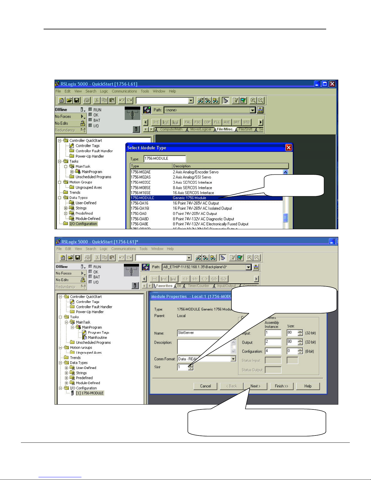
5.2. Step 2: Add and configure the SlotServer as an IO Module
• Right-click on I/O Configuration and select “New Module”.
• Choose the 1756-MODULE
Choose the
1756-MODULE
Be sure to choose the correct
Slot number in the rack where
Click Next and choose a RPI of 100 ms.
This is the rate at which the I/O image data
FieldServer Technologies 1991 Tarob Court Milpitas, California 95035 USA Web:www.fieldServer.com
Tel: (408) 262-2299 Fax: (408) 262-2296 Toll_Free: 888-509-1970 email: support@fieldServer.com
Page 11
FS-RA-CLX-LON-000_SlotServer_LonWorks_Open_Interface_(T17010) Page 11 of 28
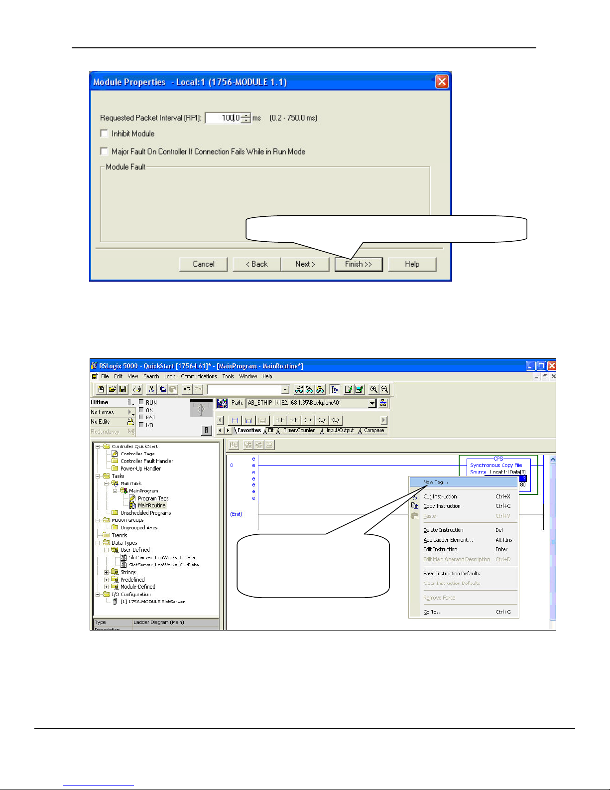
Click Finish to complete the Module Properties setup
5.3. Step 3: Write Ladder Program to Get LonWorks Input Data
• Add a CPS (Synchronous Copy File) Ladder element to synchronize the incoming Data
from the LonWorks network. Use the Input Image Data as Source.
FieldServer Technologies 1991 Tarob Court Milpitas, California 95035 USA Web:www.fieldServer.com
Tel: (408) 262-2299 Fax: (408) 262-2296 Toll_Free: 888-509-1970 email: support@fieldServer.com
You can create the
Destination Tag by right
clicking on Destination and
choosing New Tag.
Page 12

FS-RA-CLX-LON-000_SlotServer_LonWorks_Open_Interface_(T17010) Page 12 of 28
for the Destination
Create a Controller Tag of
Type REAL, dimension of 80
• Add an EQU (Compare if equal) ladder element to check when the first LonWorks data
block has been received. The block number is at offset 2 of the input image.
• Finally, add another CPS ladder element to copy the Lonworks Data from the InData_Copy
Tag to a new Controller Tag, called Lon_In_01. Also create the Tag by right clicking on
Destination and choosing New Tag. The New Tag must be of type REAL and a dimension of
76.
FieldServer Technologies 1991 Tarob Court Milpitas, California 95035 USA Web:www.fieldServer.com
Tel: (408) 262-2299 Fax: (408) 262-2296 Toll_Free: 888-509-1970 email: support@fieldServer.com
Page 13

FS-RA-CLX-LON-000_SlotServer_LonWorks_Open_Interface_(T17010) Page 13 of 28
Below is the final ladder program to access data from Lonworks Function Block In[0]
Very Important Note!
It is very important to first make a synchronous copy of the input image data before using it. If
this is not done, the input data cannot be guaranteed to be from a specific LonWorks
Function Block.
FieldServer Technologies 1991 Tarob Court Milpitas, California 95035 USA Web:www.fieldServer.com
Tel: (408) 262-2299 Fax: (408) 262-2296 Toll_Free: 888-509-1970 email: support@fieldServer.com
Page 14
FS-RA-CLX-LON-000_SlotServer_LonWorks_Open_Interface_(T17010) Page 14 of 28
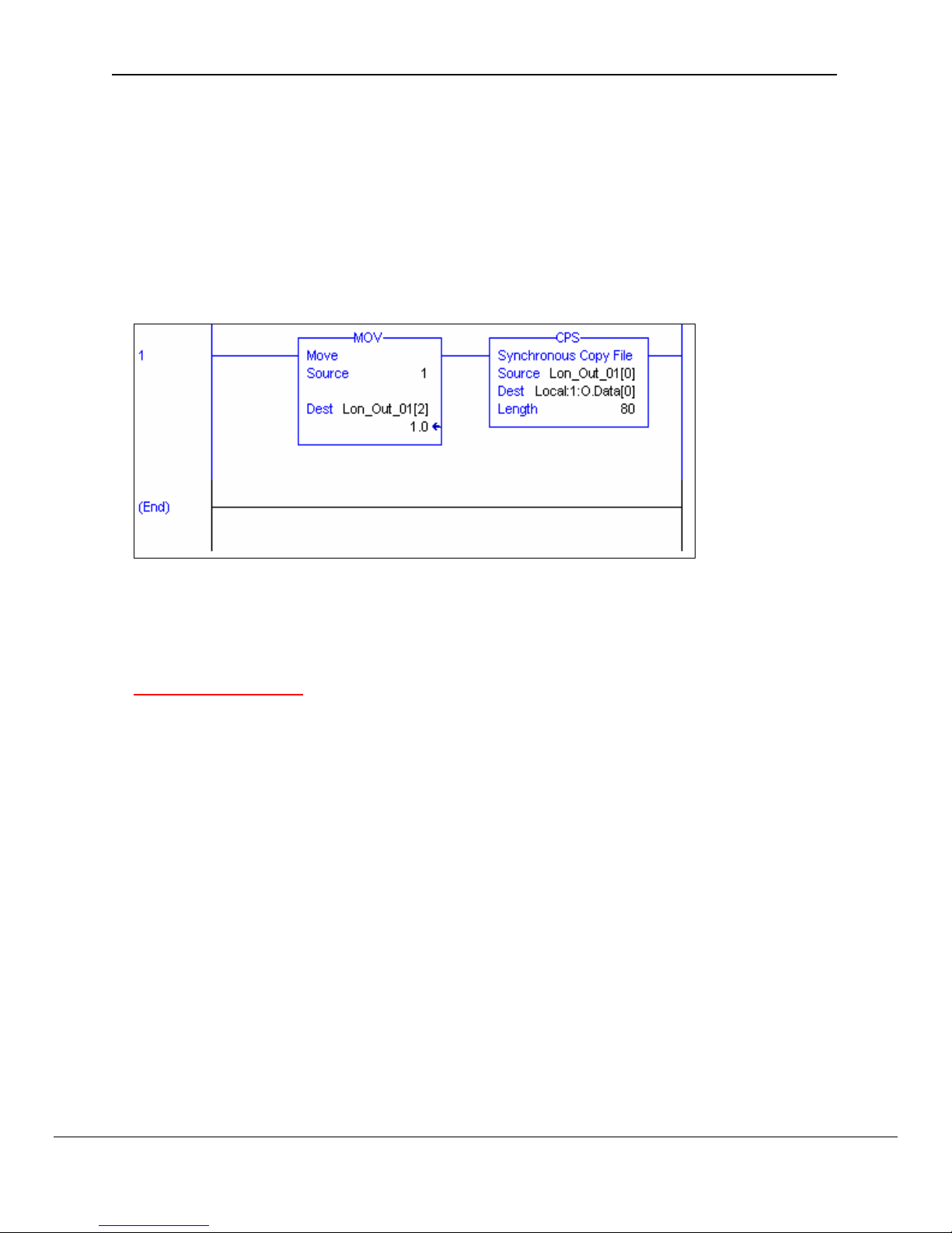
5.4. Step 4: Write Ladder Program to Send LonWorks Output Data
This step is only necessary if you need to write data to the LonWorks Network on Function
Block Out[0]
• Create a Controller Tag called Lon_Out_01 of type REAL[80].
• Add a new rung to the Ladder program and add a MOV element to move a block number
value of 1 into Lon_Out_01[2].
• Finally add a CPS ( Synchronous Copy File ) element to copy the full Lon_Out_01 tag
into the Output Image Tag.
The LonWorks Data are present from Lon_Out_01[4] to Lon_Out_01[79]
You can create a User Defined Data Type to replace the type of Lon_Out_01 mapping the
points to LonWorks point names.
Very Important Note!
It is very important to only update all the data of the Output Image Tag once using a
Synchronous File Copy element. It is not permissible to update the block number into the
Output Image Tag and then the data as this will cause an asynchronous transfer of data.
5.5. Step 5: Download the RSLogix Program and Run
Use the Who Active or Communications Path directly to Download and Run the Program on
the Controller / CPU.
5.6. Step 6: Bind LonWorks Variables
The SlotServer’s LonWorks Network Variables must be bound to other devices using a
Network Management Tool such as LonMaker. See Appendix C for more details on how to
use a Network Management Tool to make the bindings.
5.7. Step 7: Interpret the Network Variable Data
LonWorks Input Variable Values can be found in the Lon_In_01 Tag.
Lon_In_01 Tag Layout:
FieldServer Technologies 1991 Tarob Court Milpitas, California 95035 USA Web:www.fieldServer.com
Tel: (408) 262-2299 Fax: (408) 262-2296 Toll_Free: 888-509-1970 email: support@fieldServer.com
Page 15

FS-RA-CLX-LON-000_SlotServer_LonWorks_Open_Interface_(T17010) Page 15 of 28
Offset Network Variable Name SNVT_Type
0 nviAmp1 SNVT_amp
1 nviAmp2 SNVT_amp
2 - 4 nviChlr1 SNVT_chlr_status
5 nviCount1 SNVT_count_f
6 nviCount2 SNVT_count_f
7 nviCtInc1 SNVT_count_inc_f
8 nviCtInc2 SNVT_count_inc_f
9 nviFlow1 SNVT_flow_f
10 nviFreq1 SNVT_freq_hz
11 nviHVMod1 SNVT_hvac_mode
12 - 18 nviHVSts1 SNVT_hvac_status
19 nviLev1 SNVT_lev_cont
20 - 21 nviObj1 SNVT_obj_status
22 nviOcc1 SNVT_occupancy
23 nviOcc2 SNVT_occupancy
24 nviPerc1 SNVT_lev_percent
25 nviPerc2 SNVT_lev_percent
26 nviPerc3 SNVT_lev_percent
27 nviPerc4 SNVT_lev_percent
28 nviPerc5 SNVT_lev_percent
29 nviPerc6 SNVT_lev_percent
30 nviPerc7 SNVT_lev_percent
31 nviPerc8 SNVT_lev_percent
32 nviPPM1 SNVT_ppm
33 nviPress1 SNVT_press
34 nviPress2 SNVT_press
35 - 40 nviSetpt1 SNVT_temp_setpt
41 nviState1 SNVT_state
42 nviState2 SNVT_state
43 nviState3 SNVT_state
44 nviState4 SNVT_state
45 - 46 nviSw1 SNVT_switch
47 - 48 nviSw2 SNVT_switch
49 - 50 nviSw3 SNVT_switch
51 - 52 nviSw4 SNVT_switch
53 - 54 nviSw5 SNVT_switch
55 - 56 nviSw6 SNVT_switch
57 - 58 nviSw7 SNVT_switch
59 - 60 nviSw8 SNVT_switch
61 nviTemp1 SNVT_temp_p
62 nviTemp2 SNVT_temp_p
63 nviTemp3 SNVT_temp_p
64 nviTemp4 SNVT_temp_p
65 nviTemp5 SNVT_temp_p
66 nviTemp6 SNVT_temp_p
67 nviTemp7 SNVT_temp_p
68 nviTemp8 SNVT_temp_p
69 - 71 nviTodEv1 SNVT_tod_event
72 nviVltAC1 SNVT_volt_ac
73 nviVltAC2 SNVT_volt_ac
74 nviVolt1 SNVT_volt
75 nviVolt2 SNVT_volt
FieldServer Technologies 1991 Tarob Court Milpitas, California 95035 USA Web:www.fieldServer.com
Tel: (408) 262-2299 Fax: (408) 262-2296 Toll_Free: 888-509-1970 email: support@fieldServer.com
Page 16

FS-RA-CLX-LON-000_SlotServer_LonWorks_Open_Interface_(T17010) Page 16 of 28
LonWorks Output Variable Values can be found in the Lon_Out_01 Tag from Offset 4
Lon_Out_01 Tag Layout:
Offset Network Variable Name SNVT_Type
0 Protocol Type Not applicable
1 Node Status Not applicable
2 Lon Block Number [1-25] Not applicable
3 Reserved Not applicable
4 nviAmp1 SNVT_amp
5 nviAmp2 SNVT_amp
6 - 8 nviChlr1 SNVT_chlr_status
9 nviCount1 SNVT_count_f
10 nviCount2 SNVT_count_f
11 nviCtInc1 SNVT_count_inc_f
12 nviCtInc2 SNVT_count_inc_f
13 nviFlow1 SNVT_flow_f
14 nviFreq1 SNVT_freq_hz
15 nviHVMod1 SNVT_hvac_mode
16 - 22 nviHVSts1 SNVT_hvac_status
23 nviLev1 SNVT_lev_cont
24 - 25 nviObj1 SNVT_obj_status
26 nviOcc1 SNVT_occupancy
27 nviOcc2 SNVT_occupancy
28 nviPerc1 SNVT_lev_percent
29 nviPerc2 SNVT_lev_percent
30 nviPerc3 SNVT_lev_percent
31 nviPerc4 SNVT_lev_percent
32 nviPerc5 SNVT_lev_percent
33 nviPerc6 SNVT_lev_percent
34 nviPerc7 SNVT_lev_percent
35 nviPerc8 SNVT_lev_percent
36 nviPPM1 SNVT_ppm
37 nviPress1 SNVT_press
38 nviPress2 SNVT_press
39 - 44 nviSetpt1 SNVT_temp_setpt
45 nviState1 SNVT_state
46 nviState2 SNVT_state
47 nviState3 SNVT_state
48 nviState4 SNVT_state
49 - 50 nviSw1 SNVT_switch
51 - 52 nviSw2 SNVT_switch
53 - 54 nviSw3 SNVT_switch
55 - 56 nviSw4 SNVT_switch
57 - 58 nviSw5 SNVT_switch
59 - 60 nviSw6 SNVT_switch
61 - 62 nviSw7 SNVT_switch
63 - 64 nviSw8 SNVT_switch
65 nviTemp1 SNVT_temp_p
66 nviTemp2 SNVT_temp_p
67 nviTemp3 SNVT_temp_p
68 nviTemp4 SNVT_temp_p
69 nviTemp5 SNVT_temp_p
FieldServer Technologies 1991 Tarob Court Milpitas, California 95035 USA Web:www.fieldServer.com
Tel: (408) 262-2299 Fax: (408) 262-2296 Toll_Free: 888-509-1970 email: support@fieldServer.com
Page 17

FS-RA-CLX-LON-000_SlotServer_LonWorks_Open_Interface_(T17010) Page 17 of 28
Offset Network Variable Name SNVT_Type
70 nviTemp6 SNVT_temp_p
71 nviTemp7 SNVT_temp_p
72 nviTemp8 SNVT_temp_p
73 - 75 nviTodEv1 SNVT_tod_event
76 nviVltAC1 SNVT_volt_ac
77 nviVltAC2 SNVT_volt_ac
78 nviVolt1 SNVT_volt
79 nviVolt2 SNVT_volt
FieldServer Technologies 1991 Tarob Court Milpitas, California 95035 USA Web:www.fieldServer.com
Tel: (408) 262-2299 Fax: (408) 262-2296 Toll_Free: 888-509-1970 email: support@fieldServer.com
Page 18

FS-RA-CLX-LON-000_SlotServer_LonWorks_Open_Interface_(T17010) Page 18 of 28
6. Accessing All LonWorks Function Block Data
The Quickstart example is for accessing only LonWorks Data in Functional blocks:
In[0] and Out[0]
6.1. Input Data from Function Blocks In[1] to In[24]
To access Input Data Blocks In[1] up to In[24] simply add to the existing ladder program as
shown in the Quickstart example. Add a branch after the CPS element that copies the input
image Tag and copy and paste EQU and CPS elements from the first rung. Create a new
Input Tag for Lon_In_02 of type REAL and dimension 76. Finally, remember to set the
EQU Source B value to 2 to compare for incoming data from the 2nd LonWorks functional
block which is In[1].
See the ladder program below how to add In[1].
Very Important Note!
It is very important to first make a synchronous copy of the input image data before using it.
If this is not done, the input data cannot be guaranteed to be from a specific LonWorks
Function Block.
6.2. Output Data from Function Blocks Out[1] to Out[24]
To access more output blocks is slightly more complicated since we need to create a
Multiplexer in Ladder.
The basic steps are:
• Create a Counter which counts up every 100ms.
• Place the counter value into the Lon_Out_xx Tag at offset 2.
• Copy the whole Tag into the output Data Image Tag for transferring to the LonWorks
network.
The example program below shows an output counter that can count up to 25 which allows
the transfer of data into all 25 Output Function Blocks. Only 2 rungs are shown to transfer
data for blocks 1 and 2. Add more rungs with more Lon_Out_xx tags to transfer data to
other output Function Blocks.
FieldServer Technologies 1991 Tarob Court Milpitas, California 95035 USA Web:www.fieldServer.com
Tel: (408) 262-2299 Fax: (408) 262-2296 Toll_Free: 888-509-1970 email: support@fieldServer.com
Page 19

FS-RA-CLX-LON-000_SlotServer_LonWorks_Open_Interface_(T17010) Page 19 of 28
Very Important Note!
It is very important to only update all the data of the Output Image Tag once using a
Synchronous File Copy element. It is not permissible to update the block number into the
Output Image Tag and then the data as this will cause an asynchronous transfer of data.
6.3. Optimizing performance for smaller applications
If less than the full number of Function Blocks is needed, it is advisable to trim the Preset
value in the CTU element in the full SlotServer RSLogix project to the maximum block value.
The blocks should be used starting from 0 upwards. This will ensure that update rate is kept
as short as possible.
FieldServer Technologies 1991 Tarob Court Milpitas, California 95035 USA Web:www.fieldServer.com
Tel: (408) 262-2299 Fax: (408) 262-2296 Toll_Free: 888-509-1970 email: support@fieldServer.com
Page 20

FS-RA-CLX-LON-000_SlotServer_LonWorks_Open_Interface_(T17010) Page 20 of 28
For example, if only block 25 is used and all the other points are left unbound and the
project is untrimmed, when the data updates, the LonWorks driver will scan all the Map
Descriptors for all blocks which will be unnecessarily time consuming.
FieldServer Technologies 1991 Tarob Court Milpitas, California 95035 USA Web:www.fieldServer.com
Tel: (408) 262-2299 Fax: (408) 262-2296 Toll_Free: 888-509-1970 email: support@fieldServer.com
Page 21

FS-RA-CLX-LON-000_SlotServer_LonWorks_Open_Interface_(T17010) Page 21 of 28
Appendix A. Advanced Topics
Appendix A.1. Using the FieldServer RUI for Troubleshooting.
As a FieldServer enabled product, the SlotServer supports the use of the FieldServer
Utilities for diagnostic purposes. It should not be necessary to connect these utilities to the
SlotServer. However, if the need arises, then the following steps are advised:
• Download the utilities software (or just RuiNet) from www.fieldserver.com
• Download the FieldServer Utilities manual
• Get familiar with the utilities by reading the Utilities manual
• Connect to the Ethernet port on the SlotServer as prescribed by the FieldServer Utilities
manual.
• Follow directions on each of the features of the Utilities to achieve the needed result
Note: It is possible to change the profile of the SlotServer by loading a new configuration
with these utilities. However, doing so for this particular product will void the Warranty on
the product and doing so without consulting FieldServer Technologies is strongly
discouraged.
Appendix A.2. Installing SlotServer on a Remote Rack using CNB cards
Appendix A.2.1. Hardware and Software requirements
In order to perform this application, the following hardware and software is required as a
minimum:
• At least two 1756 racks, where one rack contains the CPU and the other rack
contains the SlotServer
• Two Controlnet CNB cards (with cable for connection) to connect the racks to each
other
• RSlinx
• RSLogix
• RSNetworx
• SlotServer EDS file (Available on SlotServer CD, or call Technical Support)
Note that it is possible to connect to SlotServer on a remote rack using other 1756
bridging cards. This chapter only deals with CNB, but the principles for using other
bridging cards are similar.
Appendix A.2.2. Setup
• Install the CPU and the first CNB card in the local rack.
• Install the second CNB card and the SlotServer in the remote rack.
• Connect the ControlNet Network
• Power up the racks
• Install the SlotServer EDS File using the RSLinx Hardware EDS Installation Tool.
• Make sure the SlotServer has a valid configuration loaded. The default configuration
shipped with the SlotServer should suffice.
FieldServer Technologies 1991 Tarob Court Milpitas, California 95035 USA Web:www.fieldServer.com
Tel: (408) 262-2299 Fax: (408) 262-2296 Toll_Free: 888-509-1970 email: support@fieldServer.com
Page 22

FS-RA-CLX-LON-000_SlotServer_LonWorks_Open_Interface_(T17010) Page 22 of 28
Appendix A.2.3. RSLogix configuration
In order to see the SlotServer from the CPU, the Hardware must be configured in
RSLogix as follows:
• Configure the cards in the local rack in the I/O Configuration section, including the
CPU and the local CNB card.
• Right click on the local CNB card and add the remote CNB card using the “New
Module” function.
• Right Click on the remote CNB card, and add the 1756 Backplane
• Right Click on the 1756 Backplane and add the cards that are present in the remote
rack, including the SlotServer (As a generic I/O module-see earlier section on how to
do this)
• Save the RSLogix configuration, and download it to the PLC.
The finished I/O configuration should look similar to this:
Appendix A.2.4. RSNetWorx configuration
• Open up RSNetWorx and add the two CNB Cards to the Network by dragging them
onto the Network in the Graph tab (Must be done with Edits Enabled). Follow the
prompts on the screen to configure the Chassis being used, and the cards in each
Chassis (Rack).
• Go Online with RSNetWorx, and then press “save”. This will transfer the RSNetWorx
Configuration to the Keeper.
FieldServer Technologies 1991 Tarob Court Milpitas, California 95035 USA Web:www.fieldServer.com
Tel: (408) 262-2299 Fax: (408) 262-2296 Toll_Free: 888-509-1970 email: support@fieldServer.com
Page 23

FS-RA-CLX-LON-000_SlotServer_LonWorks_Open_Interface_(T17010) Page 23 of 28
The final RSNetworx Configuration should look similar to this:
Appendix A.2.5. Testing
The SlotServer should now be visible to the CPU. Go Online with RSLogix and check
the Input buffer of the SlotServer for data. A good check is to examine offset 2 of the
input tag for a non-Zero value. If the SlotServer is multiplexing (DA_Count >1), then this
value will be cycling through the Buffer numbers, otherwise if DA_Count=1, then offset 2
will be fixed at 1. If offset 2 is zero, then the SlotServer is not being seen by the CPU,
and Diagnostics will need to be performed using RSNetWorx and RSLogix to determine
the cause of the problem.
FieldServer Technologies 1991 Tarob Court Milpitas, California 95035 USA Web:www.fieldServer.com
Tel: (408) 262-2299 Fax: (408) 262-2296 Toll_Free: 888-509-1970 email: support@fieldServer.com
Page 24

FS-RA-CLX-LON-000_SlotServer_LonWorks_Open_Interface_(T17010) Page 24 of 28
Appendix B. Troubleshooting tips
Appendix B.1. Things to check when communications has failed.
• Check for loose cabling on the LonWorks network
• Verify that the bindings in the LonWorks network have not been broken by checking the
variable status’ with the LonWorks Network Manager.
• Verify that the correct program is loaded to the CPU
• Verify that the correct data types for the tags have been used.
FieldServer Technologies 1991 Tarob Court Milpitas, California 95035 USA Web:www.fieldServer.com
Tel: (408) 262-2299 Fax: (408) 262-2296 Toll_Free: 888-509-1970 email: support@fieldServer.com
Page 25

FS-RA-CLX-LON-000_SlotServer_LonWorks_Open_Interface_(T17010) Page 25 of 28
Appendix C. Using LonMaker to Commission a SlotServer
Ensure that the SlotServer and the LonMaker PC are on the same LonWorks network.
• Open the existing Network in LonMaker, or create a new Network
• Click on “Create New Network” and follow the network wizard, making the following
selections:
Network Interface Network Attached
Management Mode Onnet (unless you are working offline)
Register Plug-ins required None
• Once Visio is open with the Network showing, drag a new device onto the drawing from the
toolbox.
• Follow the Device Network, making the following selections
Enter Device Name Commission device
Specify Device Template Upload from device
Specify Device Channel Auto Detect
Specify Device Properties Leave as is (Ping is optional)
Identify Device Service pin
Device Application Image Leave unchecked
Initial State Online
• Press the service pin on the SlotServer when asked to do so, and the SlotServer will be
commissioned.
• Drag a new function block onto the drawing from the toolbox. Give the function block a
name and ensure that it is allocated to the SlotServer device.
• Once the function block is on the drawing, you can drag input and output variables onto the
function block. When you do this, LonMaker will show you the variables available for
binding. Click on the variables you require (or use the select all option), and they will be
commissioned onto the function block.
• You are now ready to connect these variables to other devices by dragging connections
from the toolbox and connecting the variables.
FieldServer Technologies 1991 Tarob Court Milpitas, California 95035 USA Web:www.fieldServer.com
Tel: (408) 262-2299 Fax: (408) 262-2296 Toll_Free: 888-509-1970 email: support@fieldServer.com
Page 26

FS-RA-CLX-LON-000_SlotServer_LonWorks_Open_Interface_(T17010) Page 26 of 28
Appendix D. Network Variables List – LonWorks Open Interface Profile
Appendix D.1. LonWorks Network Variables Summary
The SlotServer LonWorks Open Interface Profile contains 50 Functional Blocks containing a
total of 2,600 Network Variables of different SNVT Types.
Input Data Function Blocks:
In[0] - In[24]
Output Data Function Blocks:
Out[0] - Out[24]
Each Function Block contains the following Network Variables:
(nvi for Input Data Function Blocks, and nvo for Output Data Function Blocks)
Network Variable Name SNVT_Type
nv(i)(o)Amp1 SNVT_amp
nv(i)(o)Amp2 SNVT_amp
nv(i)(o)Chlr1 SNVT_chlr_status
nv(i)(o)Count1 SNVT_count_f
nv(i)(o)Count2 SNVT_count_f
nv(i)(o)CtInc1 SNVT_count_inc_f
nv(i)(o)CtInc2 SNVT_count_inc_f
nv(i)(o)Flow1 SNVT_flow_f
nv(i)(o)Freq1 SNVT_freq_hz
nv(i)(o)HVMod1 SNVT_hvac_mode
nv(i)(o)HVSts1 SNVT_hvac_status
nv(i)(o)Lev1 SNVT_lev_cont
nv(i)(o)Obj1 SNVT_obj_status
nv(i)(o)Occ1 SNVT_occupancy
nv(i)(o)Occ2 SNVT_occupancy
nv(i)(o)Perc1 SNVT_lev_percent
nv(i)(o)Perc2 SNVT_lev_percent
nv(i)(o)Perc3 SNVT_lev_percent
nv(i)(o)Perc4 SNVT_lev_percent
nv(i)(o)Perc5 SNVT_lev_percent
nv(i)(o)Perc6 SNVT_lev_percent
nv(i)(o)Perc7 SNVT_lev_percent
nv(i)(o)Perc8 SNVT_lev_percent
nv(i)(o)PPM1 SNVT_ppm
nv(i)(o)Press1 SNVT_press
nv(i)(o)Press2 SNVT_press
nv(i)(o)Setpt1 SNVT_temp_setpt
nv(i)(o)State1 SNVT_state
nv(i)(o)State2 SNVT_state
nv(i)(o)State3 SNVT_state
nv(i)(o)State4 SNVT_state
nv(i)(o)Sw1 SNVT_switch
FieldServer Technologies 1991 Tarob Court Milpitas, California 95035 USA Web:www.fieldServer.com
Tel: (408) 262-2299 Fax: (408) 262-2296 Toll_Free: 888-509-1970 email: support@fieldServer.com
Page 27

FS-RA-CLX-LON-000_SlotServer_LonWorks_Open_Interface_(T17010) Page 27 of 28
Network Variable Name SNVT_Type
nv(i)(o)Sw2 SNVT_switch
nv(i)(o)Sw3 SNVT_switch
nv(i)(o)Sw4 SNVT_switch
nv(i)(o)Sw5 SNVT_switch
nv(i)(o)Sw6 SNVT_switch
nv(i)(o)Sw7 SNVT_switch
nv(i)(o)Sw8 SNVT_switch
nv(i)(o)Temp1 SNVT_temp_p
nv(i)(o)Temp2 SNVT_temp_p
nv(i)(o)Temp3 SNVT_temp_p
nv(i)(o)Temp4 SNVT_temp_p
nv(i)(o)Temp5 SNVT_temp_p
nv(i)(o)Temp6 SNVT_temp_p
nv(i)(o)Temp7 SNVT_temp_p
nv(i)(o)Temp8 SNVT_temp_p
nv(i)(o)TodEv1 SNVT_tod_event
nv(i)(o)VltAC1 SNVT_volt_ac
nv(i)(o)VltAC2 SNVT_volt_ac
nv(i)(o)Volt1 SNVT_volt
nv(i)(o)Volt2 SNVT_volt
FieldServer Technologies 1991 Tarob Court Milpitas, California 95035 USA Web:www.fieldServer.com
Tel: (408) 262-2299 Fax: (408) 262-2296 Toll_Free: 888-509-1970 email: support@fieldServer.com
Page 28

FS-RA-CLX-LON-000_SlotServer_LonWorks_Open_Interface_(T17010) Page 28 of 28
THIS PAGE INTENTIONALLY LEFT BLANK
FieldServer Technologies 1991 Tarob Court Milpitas, California 95035 USA Web:www.fieldServer.com
Tel: (408) 262-2299 Fax: (408) 262-2296 Toll_Free: 888-509-1970 email: support@fieldServer.com
 Loading...