

Page 1
Driver Version:
1.02
Document Revision:
3
APPLICABILITY & EFFECTIVITY
Effective for all systems manufactured after September 2009
Driver Manual
(Supplement to the FieldServer Instruction Manual)
FS-8700-102 Honeywell Zellweger IR-148
A Sierra Monitor Company
Page 2

FS-FS-8700-102 Honeywell Zellweger IR-148-8_8-Channel Manual Table of Contents
TABLE OF CONTENTS
1 Honeywell Zellweger IR-148 Description ........................................................................................................ 3
2 Driver Scope of Supply ................................................................................................................................... 3
2.1 Supplied by FieldServer Technologies for this driver ..................................................................................... 3
3 Hardware Connections ................................................................................................................................... 4
3.1 Connection Notes .......................................................................................................................................... 4
4 Data Array Parameters ................................................................................................................................... 5
5 Configuring the FieldServer as a Honeywell Zellweger IR-148 Client .............................................................. 6
5.1 Client Side Connection Descriptors ............................................................................................................... 6
5.2 Client Side Node Descriptors ......................................................................................................................... 7
5.3 Client Side Map Descriptors........................................................................................................................... 7
5.3.1 FieldServer Related Map Descriptor Parameters ................................................................................... 7
5.3.2 Driver Related Map Descriptor Parameters ........................................................................................... 7
5.3.3 Map Descriptor Example. ....................................................................................................................... 8
6 Configuring the FieldServer as a Honeywell Zellweger IR-148 Server ............................................................. 9
6.1 Server Side Connection Descriptors .............................................................................................................. 9
6.2 Server Side Node Descriptors ...................................................................................................................... 10
6.3 Server Side Map Descriptors........................................................................................................................ 11
6.3.1 FieldServer Specific Map Descriptor Parameters ................................................................................. 11
6.3.2 Driver Specific Map Descriptor Parameters ......................................................................................... 11
6.3.3 Map Descriptor Example 1 Server using Data Array: ........................................................................... 12
6.3.4 Map Descriptor Example 2: - Server using INI file: ............................................................................... 13
Appendix A. Useful Features ................................................................................................................................ 14
Appendix A.1. How Data is stored by the Driver. .................................................................................................... 14
Appendix A.1.1. One Set of consecutive Data Array elements per point/sensor. ............................................. 14
Appendix A.1.2. Extended storage ................................................................................................................... 14
Appendix B. Reference ........................................................................................................................................ 16
Appendix B.1. Supported Functions at a glance ...................................................................................................... 16
Appendix B.2. Driver Error Messages ...................................................................................................................... 16
Appendix B.3. Driver stats ....................................................................................................................................... 17
FieldServer Technologies 1991 Tarob Court Milpitas, California 95035 USA Web: www.fieldserver.com
Tel: (408) 262 2299 Fax: (408) 262 2269 Toll Free: (888) 509 1970 email: support@fieldserver.com
Page 3
FS-8700-102 Honeywell Zellweger IR-148-8_8-Channel Manual Page 3 of 17
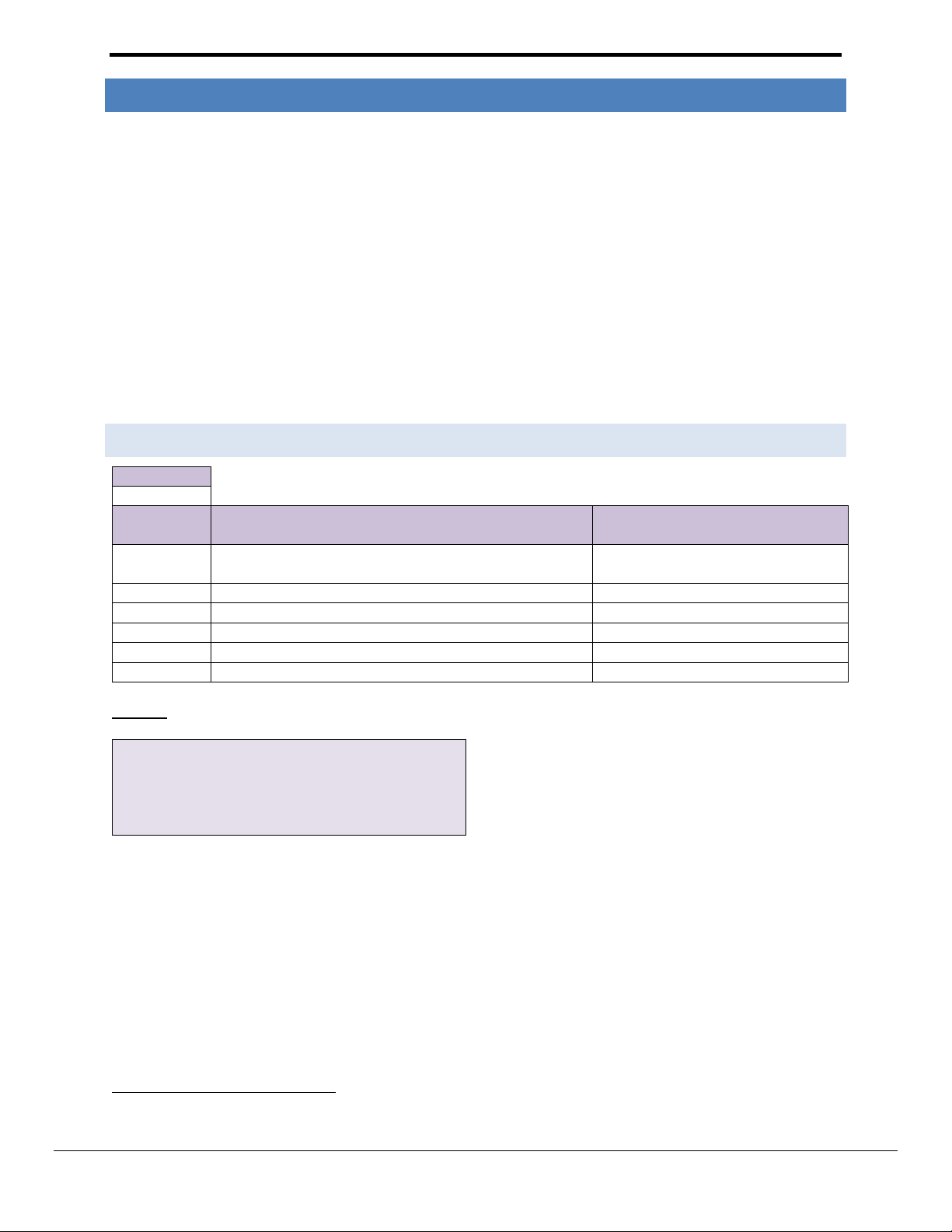
FieldServer Mode
Nodes
Comments
Client
3
Tested only 2 Nodes (IR-148 8 Point and IR-148 4 point) on separate networks
Server
3
Developed to test Client side of the Driver.
FieldServer Technologies PART #
Description
FS-8917-16
RJ45 to terminal connector cable.
1 Honeywell Zellweg er IR-148 Descr i pt ion
The Honeywell Infrared Gas Monitor (Model IR-148) detects solvents and gases such as HCFCs, HFCs and PFCs. IR148 can have 1, 4 or 8 sampling points. This InfraTox driver reports gas values, alarms and troubles for each point.
The serial driver can emulate a Client or a Server. The FieldServer and Zellweger device are connected using a RS485 network.
As a Client:
The driver listens passively for messages from the IR-148 unit and stores data extracted from the messages. The
driver cannot poll the IR-148 device for Data. The driver records some additional data age information (which is
stored in the FieldServer’s Data Arrays) because messages do not always contain information about all sensors and
depending on the IR-148 operational mode (e.g. Locked mode.), may never contain information other than for one
sensor.
As a Server:
The server side if this driver has been developed primarily to test the Client side driver as part of FieldServer’s QA
program. The driver sends messages reporting the state of the samples. The server driver can also be locked to
report the status/value of one particular sample channel.
It is possible to connect up to three Honeywell Zellweger units (IR-148) on one RS-485 network provided that one
unit is configured as a single point unit (IR-148 1 point), one as a 4-point unit (IR-148 4 point) and the other as an 8
point unit (IR-148 8-point). At this stage one device with 8 points and one with 4 points have been tested
seperately.
To allow for the possibility that the device is connected on a RS-485 network with other devices (such as the relay
module option) messages that are not 49 bytes long and which do not begin with 0xB1 will be ignored. The Driver
will, however, provide statistics for the ignored as well as the processed messages.
To see supported messages and the way the Driver stores Data, refer to Appendix A.1
Max Nodes Supported
2 Driver Sc op e of Supply
2.1 SUPPLIED BY FIELD SERVER TECHNOLOGIES FOR THI S DRIVER
FieldServer Technologies 1991 Tarob Court Milpitas, California 95035 USA Web: www.fieldserver.com
Tel: (408) 262 2299 Fax: (408) 262 2269 Toll Free: (888) 509 1970 email: support@fieldserver.com
Page 4
FS-8700-102 Honeywell Zellweger IR-148-8_8-Channel Manual Page 4 of 17
FS-8917-16
FS-X40
OR
FS-X30
GND
-
+
GND
-
+
FG
R1R2
Connect to R1 or R2 Port
+
-
G
OTHER DEVICES
INFRATOX UNIT
+
-
G
OTHER DEVICES
INFRATOX UNIT
ORANGE/WHITE
BROWN
BLUE/WHITE
FS-X20
Serial
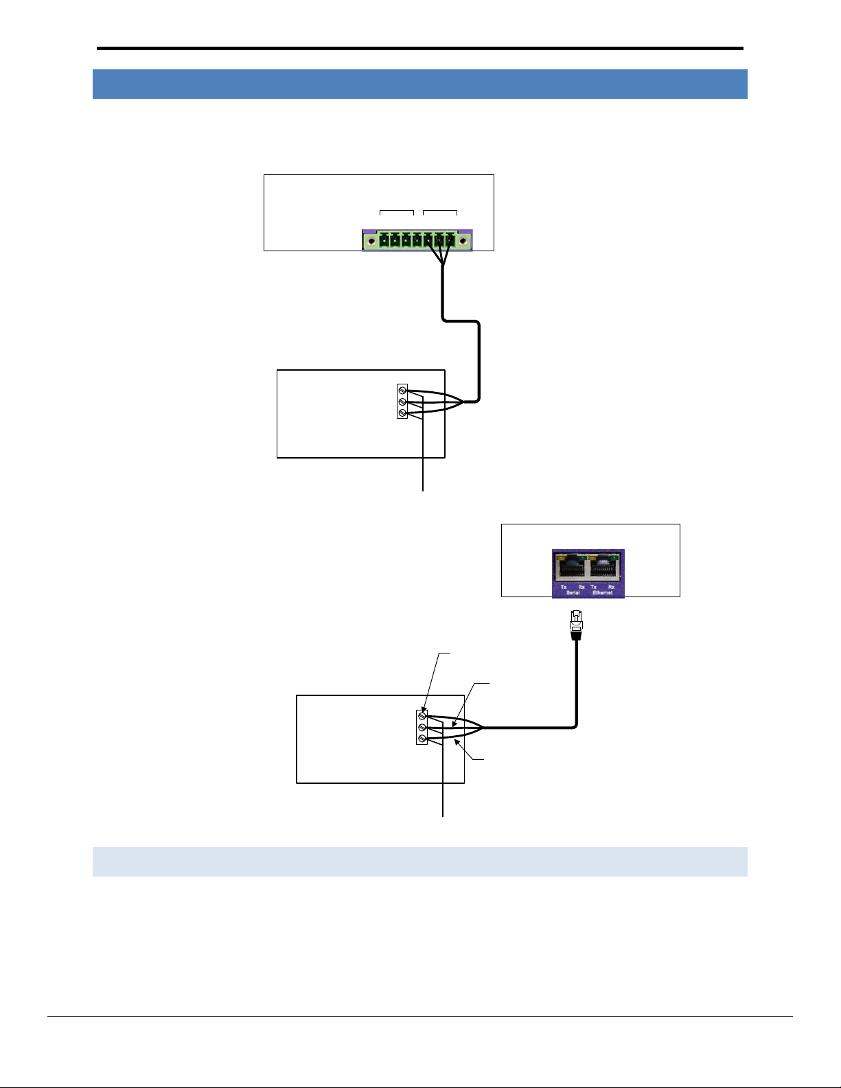
3 Hardware Connect i o ns
The FieldServer is connected to the Honeywell Zellweger IR-148 Device as shown in connection drawing.
Configure the device according to manufacturer’s instructions
3.1 CONNE CTION NOTES
Other devices must not transmit Honeywell Zellweger IR-148 49 byte messages
If connecting to the X-20, the serial port must be configured for RS-485 connection.
It is possible to connect to serial ports on the X-30 and X-40 with the use of a RS-232 to RS-485 convertor.
If connection problems are experienced when connecting with RS-485, remove the GND wire.
FieldServer Technologies 1991 Tarob Court Milpitas, California 95035 USA Web: www.fieldserver.com
Tel: (408) 262 2299 Fax: (408) 262 2269 Toll Free: (888) 509 1970 email: support@fieldserver.com
Page 5
FS-8700-102 Honeywell Zellweger IR-148-8_8-Channel Manual Page 5 of 17
Section Title
Data_Arrays
Column Title
Function
Legal Values
Data_Array_Name
Provide name for Data Array
Up to 15 alphanumeric characters
Data_Array_Format
Provide data format. Each Data Array can only take on
one format.
Float, Bit, UInt16, SInt16,
Packed_Bit, Byte, Packed_Byte,
Swapped_Byte
Data_Array_Length
Number of Data Objects. Must be larger than the data
storage area required by the Map Descriptors for the
data being placed in this array.
1-10,000
// Data Arrays
Data_Arrays
Data_Array_Name
, Data_Format
, Data_Array_Length
DA_R1
, Float
, 100
DA_R2
, Float
, 100
DA_CTL_R1
, Uint16
, 1
DA_CTL_R2
, Uint16
, 1
4 Data Array Par am eters
Data Arrays are “protocol neutral” data buffers for storage of data to be passed between protocols. It is necessary to declare
the data format of each of the Data Arrays to facilitate correct storage of the relevant data.
Example
FieldServer Technologies 1991 Tarob Court Milpitas, California 95035 USA Web: www.fieldserver.com
Tel: (408) 262 2299 Fax: (408) 262 2269 Toll Free: (888) 509 1970 email: support@fieldserver.com
Page 6
FS-8700-102 Honeywell Zellweger IR-148-8_8-Channel Manual Page 6 of 17
Section Title
Connections
Column
Title
Function
Legal Values
Port
Specify which port the device is connected to the
FieldServer
P1-P8 (with 232/485 converter), R1R21
Protocol
Specify protocol used
InfraTox or Infra-Tox
Baud*
Specify baud rate
19200 (Vendor limitation)
Parity*
Specify parity
None (Vendor limitation)
Data_Bits*
Specify data bits
8 (Vendor limitation)
Stop_Bits*
Specify stop bits
1
// Client Side Connections
Connections
Port
, Protocol
, Baud
, Parity
, Stop_Bits
R1
, InfraTox
, 19200
, None
, 1
5 Configuring th e Fi e l dServer as a Honeywell Zel l weger IR-148 Client
For a detailed discussion on FieldServer configuration, please refer to the FieldServer Configuration Manual. The
information that follows describes how to expand upon the factory defaults provided in the configuration files
included with the FieldServer (See “.csv” sample files provided with the FieldServer).
This section documents and describes the parameters necessary for configuring the FieldServer to communicate
with a Honeywell Zellweger IR-148 Server having one or eight sensors.
The configuration file tells the FieldServer about its interfaces, and the routing of data required. In order to enable
the FieldServer for Honeywell Zellweger IR-148 communications, the driver independent FieldServer buffers need
to be declared in the “Data Arrays” section, the destination device addresses need to be declared in the “Client
Side Nodes” section, and the data required from the Servers needs to be mapped in the “Client Side Map
Descriptors” section. Details on how to do this can be found below.
Note that in the tables, * indicates an optional parameter, with the bold legal value being the default.
5.1 CLIENT SIDE CONNECTION DESC RIPTORS
Example
1
Not all ports shown are necessarily supported by the hardware. Consult the appropriate Instruction manual for details of the ports available
on specific hardware.
FieldServer Technologies 1991 Tarob Court Milpitas, California 95035 USA Web: www.fieldserver.com
Tel: (408) 262 2299 Fax: (408) 262 2269 Toll Free: (888) 509 1970 email: support@fieldserver.com
Page 7

FS-8700-102 Honeywell Zellweger IR-148-8_8-Channel Manual Page 7 of 17
Section Title
Nodes
Column Title
Function
Legal Values
Node_Name
Provide name for Node
Up to 32 alphanumeric
characters
Node_ID
Irrelevant for this driver when only one Node is connected.
Otherwise the Node-ID should be the number of
points/sensors for which the Zellweger unit is configured. A
unique Node_ID is recommended for each Zellweger Unit as it
may be useful in exposing Node status information
0-255
Protocol
Specify protocol used
InfraTox, Infra-Tox.
Port
Specify at which port the device is connected to the FieldServer
Ports P1-P8 require a 232/485 converter.
P1-P82, R1-R2
// Client Side Nodes
Nodes
Node_Name,
Node_ID,
Protocol,
Port
DEV1,
1,
InfraTox,
R1
Column Title
Function
Legal Values
Map_Descriptor_Name
Name of this Map Descriptor
Up to 32 alphanumeric characters
Data_Array_Name
Name of Data Array where data is to be
stored in the FieldServer
One of the Data Array names from “Data
Array” section above
Data_Array_Offset
Starting location in Data Array
0 to maximum specified in “Data Array”
section above
Function
Function of Client Map Descriptor.
Passive_Client
Column Title
Function
Legal Values
Node_Name
Name of Node to fetch data from
One of the Node names specified in “Client Node
Descriptor” above
Length
Length of Map Descriptor
0 to Data_Array_Length (See Section 4).
Extended_Storage*
Expand Storage per point. Refer to
Appendix A.1
Yes , No
5.2 CLIENT SIDE NODE DES CRIPTORS
Example
5.3 CLIENT SIDE MAP DESCRIPT ORS
5.3.1 Field Server Related Map Des c ript or Parameters
5.3.2 Driv er Related Map Descriptor Paramete rs
2
Ports P1-P8 require a 232/485 converter.
FieldServer Technologies 1991 Tarob Court Milpitas, California 95035 USA Web: www.fieldserver.com
Tel: (408) 262 2299 Fax: (408) 262 2269 Toll Free: (888) 509 1970 email: support@fieldserver.com
Page 8

FS-8700-102 Honeywell Zellweger IR-148-8_8-Channel Manual Page 8 of 17
// Client Side Map Descriptors
Map Descriptor
Map_Descriptor_Name
, Data_Array_Name
, Data_Array_Offset
, Function
, Node_Name
, Length
CMD1
, DA_R1
, 0
, Passive Client
, DEV1
, 100
One of the Data Arrays
declared in Section 4
The Data from the
Node (Dev1) will be
stored in this Data
Array.
The Driver stores Data from device
(DEV1) with this memory location
as the starting point and onward,
in Data Array DA_R1.
This means that the FieldServer
cannot poll the target device
but monitors the device.
Extracted data from incoming
messages are stored in Data
Array DA_R1
Length forces driver to
reserve memory space for
this number of elements,
starting from memory
location defined as
Data_Array_Offset.
Length must be long enough
to store all data from Node
(Dev1)
This is the logical
name of the target
device having the
parameters
defined in section
5.2.
5.3.3 Map Descriptor Example.
If configured according to this exampe, the driver will capture and store Gas value, Alarms, Trouble, Lock and Blank messages for all (8) sensors for Node
DEV1). Refer to Appendix A.1 for detailed information about data storage.
FieldServer Technologies 1991 Tarob Court Milpitas, California 95035 USA Web: www.fieldserver.com
Tel: (408) 262 2299 Fax: (408) 262 2269 Toll Free: (888) 509 1970 email: support@fieldserver.com
Page 9

FS-8700-102 Honeywell Zellweger IR-148-8_8-Channel Manual Page 9 of 17
Section Title
Connections
Column
Title
Function
Legal Values
Port
Specify which port the device is connected to the
FieldServer
P1-P8 (with 232/485 converter), R1R23
Protocol
Specify protocol used
InfraTox or Infra-Tox
Baud*
Specify baud rate
19200 (Vendor limitation)
Parity*
Specify parity
None (Vendor limitation)
Data_Bits*
Specify data bits
8 (Vendor limitation)
// Server Side Connections
Connections
Port
, Protocol
, Baud
, Parity
, Data_Bits
R1
, InfraTox
, 19200
, None
, 8
6 Configuring th e Fi e l dServer as a Honeywell Zel l weger IR-148 Server
For a detailed discussion on FieldServer configuration, please refer to the FieldServer Configuration Manual. The
information that follows describes how to expand upon the factory defaults provided in the configuration files
included with the FieldServer (See “.csv” sample files provided with the FieldServer).
This section documents and describes the parameters necessary for configuring the FieldServer to report sensor
data to Honeywell Zellweger IR-148 Client. As a Server this driver sends Gas value, Alarm, Trouble and Lock point
messages. The driver can be locked to send data for only one particular sensor.
The configuration file tells the FieldServer about its interfaces, and the routing of data required. In order to enable
the FieldServer for Honeywell Zellweger IR-148 communications, the driver independent FieldServer buffers need
to be declared in the “Data Arrays” section, the FieldServer virtual Node(s) needs to be declared in the “Server Side
Nodes” section, and the data to be provided to the Clients needs to be mapped in the “Server Side Map
Descriptors” section. Details on how to do this can be found below.
Note that in the tables, * indicates an optional parameter, with the bold legal value being the default.
6.1 SERVER SIDE CONNECTION DESC RIPTORS
Example
3
Not all ports shown are necessarily supported by the hardware. Consult the appropriate Instruction manual for details of the ports available
on specific hardware.
FieldServer Technologies 1991 Tarob Court Milpitas, California 95035 USA Web: www.fieldserver.com
Tel: (408) 262 2299 Fax: (408) 262 2269 Toll Free: (888) 509 1970 email: support@fieldserver.com
Page 10

FS-8700-102 Honeywell Zellweger IR-148-8_8-Channel Manual Page 10 of 17
Section Title
Nodes
Column Title
Function
Legal Values
Node_Name
Provide name for Node
Up to 32 alphanumeric
characters
Node_ID
Irrelevant for this driver when only one Node is connected.
Otherwise the Node-ID should be the number of
points/sensors for which the Zellweger unit is configured. A
unique Node_ID is recommended for each Zellweger Unit as
it may be useful in exposing Node status information
0-255
Protocol
Specify protocol used
InfraTox, Infra-Tox.
Port
Specify at which port the device is connected to the
FieldServer
Ports P1-P8 require a 232/485 converter.
P1-P84, R1-R2
// Server Side Nodes
Nodes
Node_Name
, Node_ID
, Protocol
, Port
DEVR1
, 1
, InfraTox
, R1
6.2 SERVER SIDE NODE DES CRIPTORS
Example
4
Ports P1-P8 require a 232/485 converter.
FieldServer Technologies 1991 Tarob Court Milpitas, California 95035 USA Web: www.fieldserver.com
Tel: (408) 262 2299 Fax: (408) 262 2269 Toll Free: (888) 509 1970 email: support@fieldserver.com
Page 11

FS-8700-102 Honeywell Zellweger IR-148-8_8-Channel Manual Page 11 of 17
Column Title
Function
Legal Values
Map_Descriptor_Name
Name of this Map Descriptor
Up to 32 alphanumeric characters
Data_Array_Name
Name of Data Array where data is to be
stored in the FieldServer
One of the Data Array names
specified in Section 4.
Data_Array_Offset
Starting location in Data Array
0 to maximum specified in Section 4.
Function
Function of Server Map Descriptor
Wrbc
Column Title
Function
Legal Values
Node_Name
Name of Node to which data has to be sent.
One of the Node names
specified in Section 6.2
Length
Length of Map Descriptor
1 to maximum specified in
Section 4.
Da_Byte_Array_Name*
Name of Data Array used to lock the sensor. The
driver will report data for the locked sensor only.
One of the Data Array names
specified in Section 4.
Data_Byte_Offset*
Specifies offset into the Da_Byte_Array_Name Data
Array. This memory location will be checked when
the user has locked a sensor.
0 to (Data_Array_Length-1),
Data_Array_Offset
Infra_Func*
For quality assurance only:
This parameter is used to send a message to a Client
from a Map_Descriptor_Name*.ini file. The
Data_Array_Offset value will be used as the line
number from INI to send.
INFRA_SIMULATION: only the numbered line will be
sent.
INFRA_SIMULATION_ALL: Starting at the numbered
line all lines will be sent one by one until the end of
the file is reached.
INFRA_SIM_ALL_REPEAT: All lines from the
numbered line will be sent until the end of the file is
reached and then the cycle will repeat from the
numbered line.
Note: Ini must show all bytes as two character hex
representation and the first line should be
// FILE_IN_HEX_FORMAT
INFRA_SIMULATION,
INFRA_SIMULATION_ALL,
INFRA_SIM_ALL_REPEAT,
-
6.3 SERVER SIDE MAP DESCRIPT O RS
6.3.1 Field Server Specific Map D escriptor Parameters
6.3.2 Driv er Specific Map Descriptor Parame ters
FieldServer Technologies 1991 Tarob Court Milpitas, California 95035 USA Web: www.fieldserver.com
Tel: (408) 262 2299 Fax: (408) 262 2269 Toll Free: (888) 509 1970 email: support@fieldserver.com
Page 12

FS-8700-102 Honeywell Zellweger IR-148-8_8-Channel Manual
// Server Side Map Descriptors
Map Descriptors
Map_Descriptor_Name
, Data_Array_Name
, Data_Array_Offset
, Function
, Node_Name
, Length
, Da_Byte_Name
, Da_Byte_Oset
SMD1
, DA_R1
, 0
, Wrbc
, DEV1
, 100
, DA_CTL_R1
, 0
Driver will look
into this data array
to send Zellweger
message to
Zellweger 8
Channel Client.
Data Array Offset
indicates the
starting memory
location for the
Data to be sent to
the Node (DEV1).
Wrbc function makes
this Server an Active
Server. The Server
continuously writes
data for each sensor.
Client Node which
receives data from
the Server..
Length should be
sufficient to store
data for all
sensors for a
Node.
Name of Data
Array used to
lock sensor.
Driver will report
data for locked
sensor only.
The memory
location within the
Da_Byte_Name
Data Array at which
the user can put the
sensor number to
be locked.
Page 12 of 17
6.3.3 Map Descriptor Example 1 Server using Data Array:
The following Map Descriptor enables this Driver to send data for all 8 sensors to the Node (DEV1) connected at the FieldServer. Refer to Section 4 for the
Data Array format.
The Driver can send Gas value messages, Alarm messages, Trouble messages and lock point messages. The driver can also be locked to send data for only one
particular sensor. In this example, if a valid (1-8) sensor number is inserted at offset 0 in the Data Array DA_CTL_R1, the driver will only send data for that
particular sensor. To disable the lock, insert an invalid (0 or >8) number.
FieldServer Technologies 1991 Tarob Court Milpitas, California 95035 USA Web: www.fieldserver.com
Tel: (408) 262 2299 Fax: (408) 262 2269 Toll Free: (888) 509 1970 email: support@fieldserver.com
Page 13

FS-8700-102 Honeywell Zellweger IR-148-8_8-Channel Manual
// Server Side Map Descriptors
Map Descriptors
Map_Descriptor_Name,
Data_Array_Name,
Data_Array_Offset,
Function,
Node_Name
Length
Infra_Func
SMD1.ini,
Dummy,
2,
wrbc,
DEV1,
1,
INFRA_SIMULATION,
Data Array Offset indicates the line
number to send to Node (DEV1).
Wrbc function makes this Server an
Active Server. This Server continuously
sends data from the specified line in the
SMD1.ini file.
Server sends data to this
Node connected to the
FieldServer.
Length should be
set to 1.
Specifies the use of the
INI file as the Data
source.
Page 13 of 17
6.3.4 Map Descriptor Example 2: - Server using INI file:
This Map Descriptor will enable the Driver to send the 2nd line from the SMD1.ini to the Node DEV1 irrespective of the contents. The line may contain up to
2000 characters.
FieldServer Technologies 1991 Tarob Court Milpitas, California 95035 USA Web: www.fieldserver.com
Tel: (408) 262 2299 Fax: (408) 262 2269 Toll Free: (888) 509 1970 email: support@fieldserver.com
Page 14

FS-8700-102 Honeywell Zellweger IR-148-8_8-Channel Manual Page 14 of 17
Offset
Sensor
Contents
Description
0 1 Alarm or Trouble
Set non-zero if alarm or a trouble has been reported. Set to zero if
neither are currently being reported.
1 1 Alarm Type
0 = None
1 = Caution
2 = Warning
3 = Alarm
2 1 Trouble
0 = None
1 = Trouble
3 1 Gas Value
Gas value multiplied by 100. If configured, scaling will be applied.
4 1 Gas Units
1st 3 bytes of gas units are written as ASCII characters.
5 1 Gas Units
6 1 Gas Units
7 1 State
0 = Enabled
1 = Disabled
8 1 Gas Value Valid
1 = Gas Value updated with most recent message.
0 = Gas Value not updated.
9 1 Gas Value Age
In seconds since last update. Initial (and max) value = 0xffff
10 1 Sensor Data Age
Time since last message containing data about this sensor.
In seconds since last update. Initial (and max) value = 0xffff
11..21
2
22..32
3
33..43
4
44..54
5
55..65
6
66..76
7
77..87
8
Offset
Sensor
Contents
Description
0 1 Alarm or Trouble
Non-zero if alarm or a trouble has been reported.
Zero if neither are currently being reported.
1 1 Alarm Type
0 = None, 1 = Caution, 2 = Warning, 3 = Alarm
2 1 Trouble
0=None, 1=Trouble
3 1 Gas Value
Gas value multiplied by 100 is stored here. When stored, if
configured, scaling will be applied.
4 1 Gas Units
1st 3 bytes of gas units are written here as ASCII characters.
5 1 Gas Units
6 1 Gas Units
7 1 State
0 = Enabled, 1 = Disabled
8 1 Gas Value Valid
1 = Gas Value updated with most recent message.
0 = Gas Value not updated.
9 1 Gas Value Age
In seconds since last update.
Initial (and max) value = 0xffff
10 1 Sensor Data Age
Age since last message, containing data from this sensor in
seconds. Initial (and max) value = 0xffff
11 1 I/O State
255 = unknown, 0=Warm up, 1 = Ready, 2 = Trouble, 3=
Appendix A. Useful Featur es
Appendix A.1. How Dat a is stored by the Driver.
Appendix A.1.1. One Set of c o n secutive D a ta Array el e ments per p o i n t /sensor.
Appendix A.1.2. Extended sto rage
FieldServer Technologies 1991 Tarob Court Milpitas, California 95035 USA Web: www.fieldserver.com
Tel: (408) 262 2299 Fax: (408) 262 2269 Toll Free: (888) 509 1970 email: support@fieldserver.com
Page 15

FS-8700-102 Honeywell Zellweger IR-148-8_8-Channel Manual Page 15 of 17
Offset
Sensor
Contents
Description
Cal/Setup
12 1 Alarm Latched Status
0=No, 1=Yes
13 1 Audio On Status
0=No, 1= Yes
14
1
Alarm Latching
Preference
On Caution (0=No, 1= Yes)
15
1
Alarm Latching
Preference
On Warning(0=No, 1= Yes)
16
1
Alarm Latching
Preference
On Alarm(0=No, 1= Yes)
17 1 Audio On Preference
On Caution (0=No, 1= Yes)
18 1 Audio On Preference
On Warning(0=No, 1= Yes)
19 1 Audio On Preference
On Alarm(0=No, 1= Yes)
20 1 Audio On Preference
On Trouble(0=No, 1= Yes)
21 1 Audio On Preference
On Auxilary(0=No, 1= Yes)
22-24
1
Spare
25..49
2
50.-74
3
75.- 99
4
100-124
5
125..149
6
150.-174
7
175.- 199
8
FieldServer Technologies 1991 Tarob Court Milpitas, California 95035 USA Web: www.fieldserver.com
Tel: (408) 262 2299 Fax: (408) 262 2269 Toll Free: (888) 509 1970 email: support@fieldserver.com
Page 16

FS-8700-102 Honeywell Zellweger IR-148-8_8-Channel Manual Page 16 of 17
Message Types
Notes
Gas Value Message
Message reports a gas value and units.
Trouble Message
Message reports a trouble for one sensor
Blank Message
Message used to flash Honeywell Zellweger IR-148 display
Alarm Message
Message reports an alarm (C/W/A) for one sensor
Locked Point Message
Unit is locked onto a single sample.
Other 49 byte messages beginning 0xb1
Discarded but driver report stats on these messages as described
in Appendix B.3.
Other 49 byte messages
Other messages
Error Message
Description and Action Required
INFRA: #1 Err. Da <%s> length
Reqd/exist <%d/%d> Md <%s>
where md offset <%d>
This error will be generated when the driver tries to store data for a sensor
but the corresponding Data Array is not long enough. Set the Data Array
length as indicated..
INFRA:#2 Err. Incoming data is
being abandoned on port R-P%d
Honeywell Zellweger IR-148-8.8-Channel or another unit is connected at the
indicated port of the FieldServer but the Configuration file does not define a
Map Descriptor to capture data from this unit. Change the CSV file to define
a Map Descriptor to communicate with this device if required.
INFRA:#3 ERR. Invalid Node_id
%d, Valid 1-8
If there are multiple Nodes then make the Node_ID the number of points
(sensors) for which Zellweger units are configured.
Infra:#4 Err. Test file <%s> not
found.
In Simulation mode the driver can send messages from files indicated by the
Map Descriptor name. Check that the required file exists and that it is not in
use by another application, or change the mode from simulation to
operation by deleting the parameter “INFRA_SIMULATION” from .the CSV
file.
INFRA:#11 Err. Illegal MD
Function for Md <%s>
Set Map Descriptor’s function to Passive_Client if driver is configured as a
Client or Wrbc if configured as a Server.
INFRA:#12 Err. Illegal MD length
<%s>
The Map Descriptor length parameter is either not defined or set to 0. Set
the Map Descriptor length to 100.
INFRA:#13 Err. Illegal Infra_func
for Md <%s>
This error will be generated if you are using the Infra_func parameter with
an incorrect value. See section 0 for legal values.
INFRA:#21 Err. Da <%s> length
Reqd/exist <%d/%d> Md <%s>
where md offset <%d>
This error will be generated when the driver tries to send a message to the
Client, but the Data Array used to compose the message is insufficiently long
to hold information for all 8 sensors. Set the Data Array length as indicated.
INFRA:#22 Err. Diagnostic line
<%d> ignored.
In Server mode the driver does not send messages from lines starting with #
or //. Change the Data_Array_Offset parameter for the indicated line in the
ini file.
Appendix B. Referenc e
Appendix B.1. Supported Fu nctions at a glance
Appendix B.2. Driver E rror Messages
Some configuration errors might produce an error every time a poll is generated. This will fill the error buffer
quickly and not add any clarity. For this reason the driver suppresses subsequent similar messages. Thus it is
possible for the same error produced by multiple Map Descriptors to produce only one error message.
Subsequent error messages can be seen on the driver message screen.
Note : In the actual message you will see that %d has been replaced by an integer, %s by text indicating a data
array name or map descriptor name and %x by two hex characters.
Edit CSV file, download the modified file and reset the FieldServer to have the changes take effect.
FieldServer Technologies 1991 Tarob Court Milpitas, California 95035 USA Web: www.fieldserver.com
Tel: (408) 262 2299 Fax: (408) 262 2269 Toll Free: (888) 509 1970 email: support@fieldserver.com
Page 17

FS-8700-102 Honeywell Zellweger IR-148-8_8-Channel Manual Page 17 of 17
Error Message
Description and Action Required
INFRA:#41 FYI. Write-thru not
Possible On MD <%s>
If an Upstream Device writes a value at a memory location under the
influence of the given Map Descriptor, the Write-thru operation will be
cancelled as the Driver cannot write to an UnfraTox unit..
Infra:#51 FYI. You could use an
Array called <%s> to expose
diagnostic info.
It is possible to define a Data Array known as “Infra-stats” (see Appendix
A.1.1) This Data Array is very useful for statistics purposes.
// Expose Driver Operating Stats.
Data_Arrays
Data_Array_Name,
Data_Format,
Data_Array_Length
Infra-stats,
UINT32,
200
Stat #
Stats
Description
0
INFRA_TROUBLE_MSG_RECV
Number of trouble messages received
1
INFRA_TROUBLE_WITH_ALARM_MSG_RECV
Number of Alarm as well as Trouble messages
reported
2
INFRA_ALARM_MSG_RECV
Number of Alarm messages reported
3
INFRA_GAS_VALUE_MSG_RECV
Number of Gas Value messages reported
4
INFRA_GAS_VALUE_WITH_ALARM_MSG_RECV
Number of Gas value as well as Alarm messages
reported.
5
INFRA_LOCK_MSG_RECV
Number of Lock messages reported
6
INFRA_BLANK_MSG_RECV
Number of Blank messages reported
10
INFRA_ST_0xB1_49_RECV_DISC
Number of discarded messages starting with 0xB1
with length 49 bytes
11
INFRA_BAD_ST_49_RECV_DISC
Number of discarded messages not starting with 0xB1
with length 49 bytes
12
INFRA_NOT_49_RECV_DISC
Number of discarded messages with length not 49
bytes.
13
INFRA_NOT_49_RECV_BYTES_DISC
Length of the latest discarded message with length
not 49 bytes.
20
INFRA_BAD_CRC_MSG_DISC
Number of messages discarded because of bad
checksum.
Appendix B.3. Driver s tats
In addition to the standard FieldServer operating statistics the driver can expose certain key stats in a Data Array
which can then be monitored by an upstream device. Adding the following to the configuration file will activate
these stats for a driver configured as a Client.
For the Node connected at R1; Offset = Stat number
Example: The number of messages discarded because of bad start can be found at Offset 11 in Infra-Stats Data
Array.
For the Node connected at R2; Offset = 100 + Stat number
Example: The number of messages discarded because of bad start can be found at Offset 111 in Infra-Stats Data
Array.
FieldServer Technologies 1991 Tarob Court Milpitas, California 95035 USA Web: www.fieldserver.com
Tel: (408) 262 2299 Fax: (408) 262 2269 Toll Free: (888) 509 1970 email: support@fieldserver.com
 Loading...